ecm terminal SUZUKI SX4 2006 1.G Service Workshop Manual
[x] Cancel search | Manufacturer: SUZUKI, Model Year: 2006, Model line: SX4, Model: SUZUKI SX4 2006 1.GPages: 1556, PDF Size: 37.31 MB
Page 611 of 1556
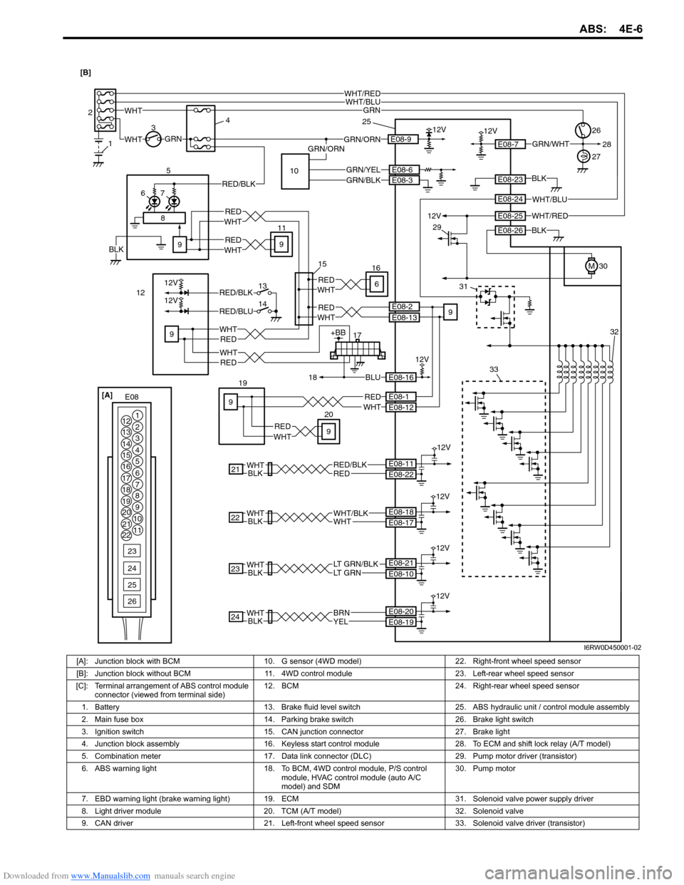
Downloaded from www.Manualslib.com manuals search engine ABS: 4E-6
17+BB
18BLU
WHT12VGRN/ORN 34
30E08-9
RED
WHT 1226
WHT/RED
12V
E08-7
19GRN
GRN
E08-16
12V
5
76
21REDRED/BLK
12V
BLKWHTE08-22 E08-11
23BLKWHTLT GRN/BLKLT GRN
12V
E08-10 E08-21
E08-23
E08-26
E08-1E08-12
24BLKWHT
12V
YELBRNE08-19 E08-20
27
1 2
RED/BLK
WHTRED
WHTRED
WHTRED9
E08-2E08-13WHT
E08-6
RED
9
9
11
9
9
9
REDWHT
WHTRED
12VE08-25
M
BLK
BLK
WHT/BLUWHT/RED
WHT/BLUE08-24
WHT
E08 [A]
1
2
3
4
5
6
7 12
13
14
15
16
17
18
19
20
21
228
9
10
11
23
24
25
26
GRN/WHT
22
12V
BLKWHTWHTWHT/BLKE08-17 E08-18
GRN/ORN28
2033
31
29
25
15
32
GRN/YELE08-3GRN/BLK
8
12V
12V
13
14RED/BLK
RED/BLU
WHTRED6
16
10
BLK [B]
I6RW0D450001-02
[A]: Junction block with BCM 10. G sensor (4WD model) 22. Right-front wheel speed sensor
[B]: Junction block without BCM 11. 4WD control module 23. Left-rear wheel speed sensor
[C]: Terminal arrangement of ABS control module
connector (viewed from terminal side)12. BCM 24. Right-rear wheel speed sensor
1. Battery 13. Brake fluid level switch 25. ABS hydraulic unit / control module assembly
2. Main fuse box 14. Parking brake switch 26. Brake light switch
3. Ignition switch 15. CAN junction connector 27. Brake light
4. Junction block assembly 16. Keyless start control module 28. To ECM and shift lock relay (A/T model)
5. Combination meter 17. Data link connector (DLC) 29. Pump motor driver (transistor)
6. ABS warning light 18. To BCM, 4WD control module, P/S control
module, HVAC control module (auto A/C
model) and SDM30. Pump motor
7. EBD warning light (brake warning light)19. ECM 31. Solenoid valve power supply driver
8. Light driver module 20. TCM (A/T model) 32. Solenoid valve
9. CAN driver 21. Left-front wheel speed sensor 33. Solenoid valve driver (transistor)
Page 627 of 1556
Downloaded from www.Manualslib.com manuals search engine ABS: 4E-22
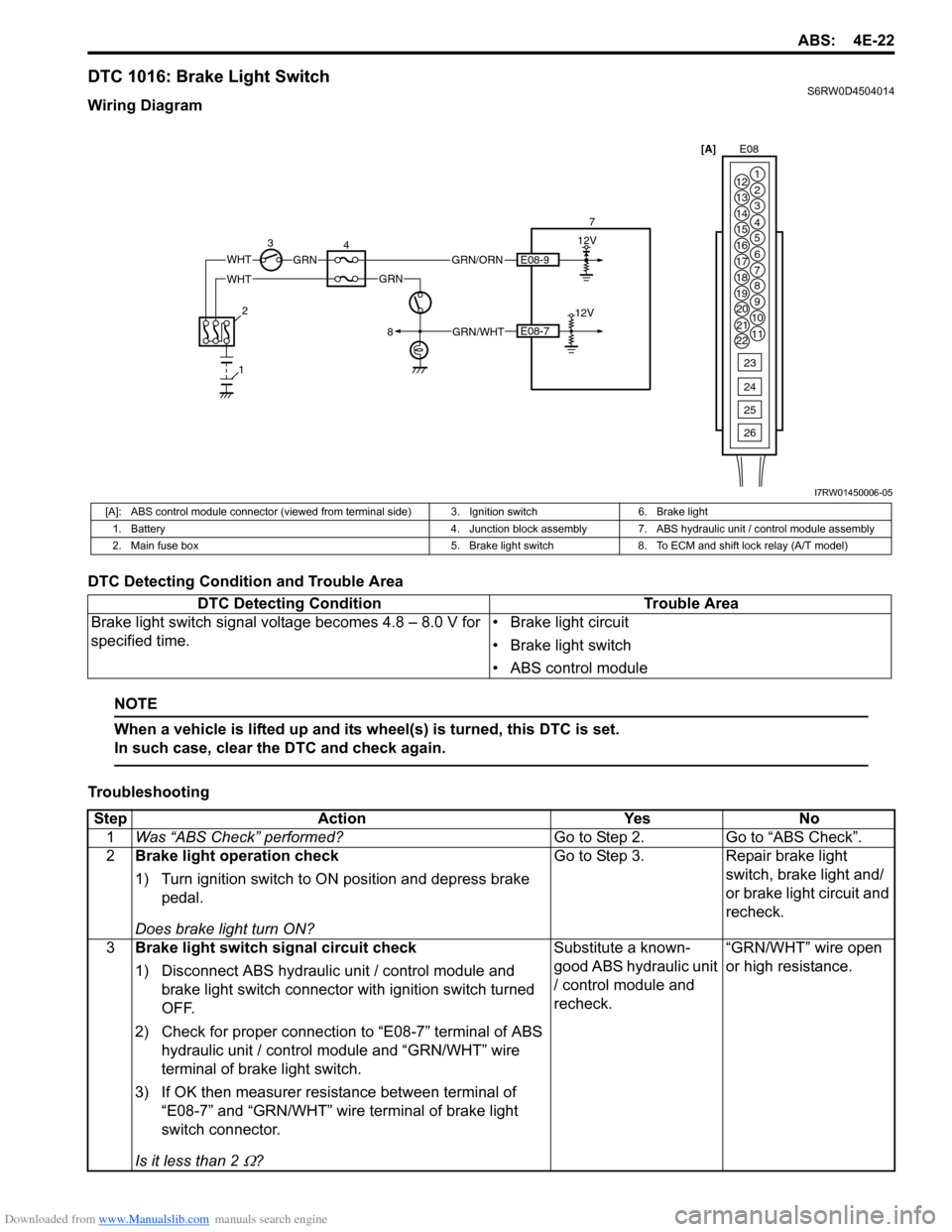
DTC 1016: Brake Light SwitchS6RW0D4504014
Wiring Diagram
DTC Detecting Condition and Trouble Area
NOTE
When a vehicle is lifted up and its wheel(s) is turned, this DTC is set.
In such case, clear the DTC and check again.
Troubleshooting
WHTGRN
34 712V
E08-7
E08-9GRN/ORN
2
8
112V
GRN/WHT
WHTGRN[A]E08
1
2
3
4
5
6
7 12
13
14
15
16
17
18
19
20
21
228
9
10
11
23
24
25
26
I7RW01450006-05
[A]: ABS control module connector (viewed from terminal side) 3. Ignition switch 6. Brake light
1. Battery 4. Junction block assembly 7. ABS hydraulic unit / control module assembly
2. Main fuse box 5. Brake light switch 8. To ECM and shift lock relay (A/T model)
DTC Detecting Condition Trouble Area
Brake light switch signal voltage becomes 4.8 – 8.0 V for
specified time.• Brake light circuit
• Brake light switch
• ABS control module
Step Action Yes No
1Was “ABS Check” performed?Go to Step 2. Go to “ABS Check”.
2Brake light operation check
1) Turn ignition switch to ON position and depress brake
pedal.
Does brake light turn ON?Go to Step 3. Repair brake light
switch, brake light and/
or brake light circuit and
recheck.
3Brake light switch signal circuit check
1) Disconnect ABS hydraulic unit / control module and
brake light switch connector with ignition switch turned
OFF.
2) Check for proper connection to “E08-7” terminal of ABS
hydraulic unit / control module and “GRN/WHT” wire
terminal of brake light switch.
3) If OK then measurer resistance between terminal of
“E08-7” and “GRN/WHT” wire terminal of brake light
switch connector.
Is it less than 2
Ω?Substitute a known-
good ABS hydraulic unit
/ control module and
recheck.“GRN/WHT” wire open
or high resistance.
Page 658 of 1556
Downloaded from www.Manualslib.com manuals search engine 5A-10 Automatic Transmission/Transaxle:
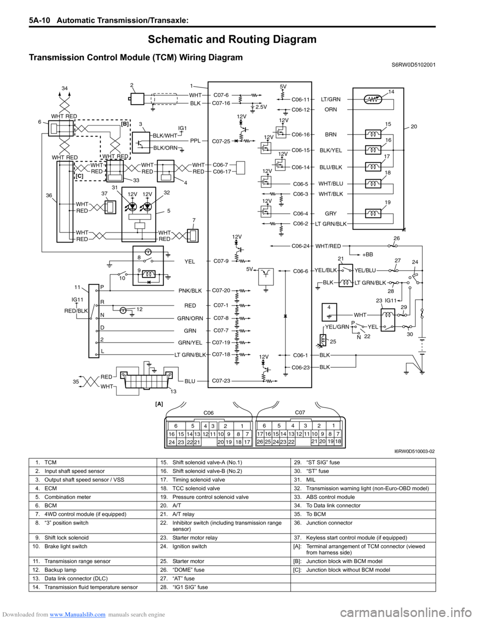
Schematic and Routing Diagram
Transmission Control Module (TCM) Wiring DiagramS6RW0D5102001
12V
12V
12V
IG1
118
9
10
P
R
N
D
2
L12
2.5V
5V
12V
5V
12V
12V
12V
WHT
BLK
BLK
BLK
BLK
PPLBLK/WHT
BLK/ORN
IG11
RED/BLK
YEL/BLKYEL/BLU
LT GRN/BLK
+BB
WHT/RED
14
20 15
16
17
19
12V18
1 2
3
132126
24 27
28
29
30
65
16 15 14 13 12 1143
24 23 212210 9 8 721
19 20 18 17 C06
17 16
26 2515 14 65 342
13 12
23 22 2411 10 9
21 20 1987
18 1 C07
[A]
22
25
YELYEL/GRN
WHT
P
N
BRN LT/GRN
ORN
BLK/YEL
BLU/BLK
GRY
LT GRN/BLKWHT/BLU
WHT/BLK
C06-11
C06-12
C06-16
C06-15
C06-14
C06-4
C06-2
C06-1
C06-23C06-6 C06-24C06-5
C06-3
RED
GRN GRN/ORNPNK/BLK
GRN/YEL
LT GRN/BLKC07-6
C07-16
C07-23 C07-25
C07-20
C07-1
C07-8
C07-7
C07-19
C07-18
4IG11 23
C07-9
YEL
RED
WHTBLU35 34
3637
5REDWHT
7
WHT
RED
33
4
6
C06-7C06-17WHT
REDREDWHT
WHT
12V12V
WHTRED
WHTREDREDWHT
31
32
RED
WHTRED[B]
[C]
I6RW0D510003-02
1. TCM 15. Shift solenoid valve-A (No.1) 29. “ST SIG” fuse
2. Input shaft speed sensor 16. Shift solenoid valve-B (No.2) 30. “ST” fuse
3. Output shaft speed sensor / VSS 17. Timing solenoid valve 31. MIL
4. ECM 18. TCC solenoid valve 32. Transmission warning light (non-Euro-OBD model)
5. Combination meter 19. Pressure control solenoid valve 33. ABS control module
6. BCM 20. A/T 34. To Data link connector
7. 4WD control module (if equipped) 21. A/T relay 35. To BCM
8. “3” position switch 22. Inhibitor switch (including transmission range
sensor)36. Junction connector
9. Shift lock solenoid 23. Starter motor relay 37. Keyless start control module (if equipped)
10. Brake light switch 24. Ignition switch [A]: Terminal arrangement of TCM connector (viewed
from harness side)
11. Transmission range sensor 25. Starter motor [B]: Junction block with BCM model
12. Backup lamp 26. “DOME” fuse [C]: Junction block without BCM model
13. Data link connector (DLC) 27. “AT” fuse
14. Transmission fluid temperature sensor 28. “IG1 SIG” fuse
Page 668 of 1556
Downloaded from www.Manualslib.com manuals search engine 5A-20 Automatic Transmission/Transaxle:
DTC No. Detecting itemDetecting condition
(DTC will set when detecting)AB
�) �UP0602Control module Programming
ErrorData programming error. — —
�) P0705Transmission range sensor circuit
malfunction (PRNDL input)Multiple signals are inputted simultaneously.1 driving
cycle1 driving
cycle
�) P0707Transmission range sensor circuit
lowNo sensor signal is inputted.2 driving
cycles2 driving
cycles
�) *P0711Transmission Fluid Temperature
Sensor “A” circuit Range /
PerformanceTransmission temperature sensor signal is no
change for specified time continuously.2 driving
cycles2 driving
cycles*
�) P0712Transmission fluid temperature
sensor circuit lowSensor output voltage is too low.1 driving
cycle1 driving
cycle
�) P0713Transmission fluid temperature
sensor circuit highSensor output voltage is too high.1 driving
cycle1 driving
cycle
�) P0717Input / Turbine speed sensor
circuit no signalNo sensor signal is detected although output
speed sensor signal is inputted.1 driving
cycle1 driving
cycle
�) P0722Output speed sensor circuit no
signalNo sensor signal is inputted although input
speed sensor signal is inputted.1 driving
cycle1 driving
cycle
�) *P0741Torque converter clutch circuit
performance or stuck offDifference in revolution between engine and
input shaft is too large although TCM is
commanding TCC solenoid valve to turn ON.2 driving
cycles2 driving
cycles*
�) *P0742Torque converter clutch circuit
stuck onDifference in revolution between engine and
input shaft is too small although TCM is
commanding TCC solenoid valve to turn OFF.2 driving
cycles2 driving
cycles*
�) *P0751
Shift solenoid-A (No.1)
performance or stuck offActual gear position is 3rd gear although TCM
command is for 2nd gear.2 driving
cycles2 driving
cycles*
�) *P0752 Shift solenoid-A (No.1) stuck onActual gear position is 2nd gear although TCM
command is for 3rd gear.2 driving
cycles2 driving
cycles*
�) *P0756Shift solenoid-B (No.2)
performance or stuck offActual gear position is 3rd gear although TCM
command is for 4th gear.2 driving
cycles2 driving
cycles*
�) *P0757 Shift solenoid-B (No.2) stuck onActual gear position is 4th gear although TCM
command is for 3rd gear.2 driving
cycles2 driving
cycles*
�) P0787Shift / Timing solenoid control
circuit lowVoltage of timing solenoid terminal is low
although TCM is commanding timing solenoid to
turn ON.1 driving
cycle1 driving
cycle
�) P0788Shift / Timing solenoid control
circuit highVoltage of timing solenoid terminal is high
although TCM is commanding timing solenoid to
turn OFF.1 driving
cycle1 driving
cycle
�) P0961Pressure Control Solenoid “A”
Control Circuit Range /
PerformanceDifference between actual current of control
solenoid valve circuit and current of control
solenoid valve circuit calculated by ECM is more
than specification.1 driving
cycle1 driving
cycle
�) P0962Pressure control solenoid control
circuit lowNo electric flow is detected on pressure control
solenoid circuit.1 driving
cycle1 driving
cycle
�) P0963Pressure control solenoid control
circuit highToo much electric flow is detected on pressure
control solenoid circuit.1 driving
cycle1 driving
cycle
�) P0973Shift solenoid-A (No.1) control
circuit lowVoltage of shift solenoid terminal is low although
TCM is commanding shift solenoid to turn ON.1 driving
cycle1 driving
cycle
�) P0974
Shift solenoid-A (No.1) control
circuit highVoltage of shift solenoid terminal is high
although TCM is commanding shift solenoid to
turn OFF.1 driving
cycle1 driving
cycle
�) P0976Shift solenoid-B (No.2) control
circuit lowVoltage of shift solenoid terminal is low although
TCM is commanding shift solenoid to turn ON.1 driving
cycle1 driving
cycle
�) P0977Shift solenoid-B (No.2) control
circuit highVoltage of shift solenoid terminal is high
although TCM is commanding shift solenoid to
turn OFF.1 driving
cycle1 driving
cycle
�) P1702Internal control module memory
check sum errorCalculation of current data stored in TCM is not
correct comparing with pre-stored checking data
in TCM.1 driving
cycle1 driving
cycle
Page 690 of 1556
Downloaded from www.Manualslib.com manuals search engine 5A-42 Automatic Transmission/Transaxle:
DTC P0602: Control Module Programming ErrorS6RW0D5104047
System Description
Internal control module is installed in ECM.
DTC Detecting Condition and Trouble Area
DTC Confirmation Procedure
1) Connect scan tool to DLC with ignition switch turned OFF.
2) Turn ON ignition switch and clear DTC, pending DTC and freeze frame data by using scan tool.
3) Start engine and run it at idle if possible.
4) Check DTC and pending DTC by using scan tool.
DTC Troubleshooting
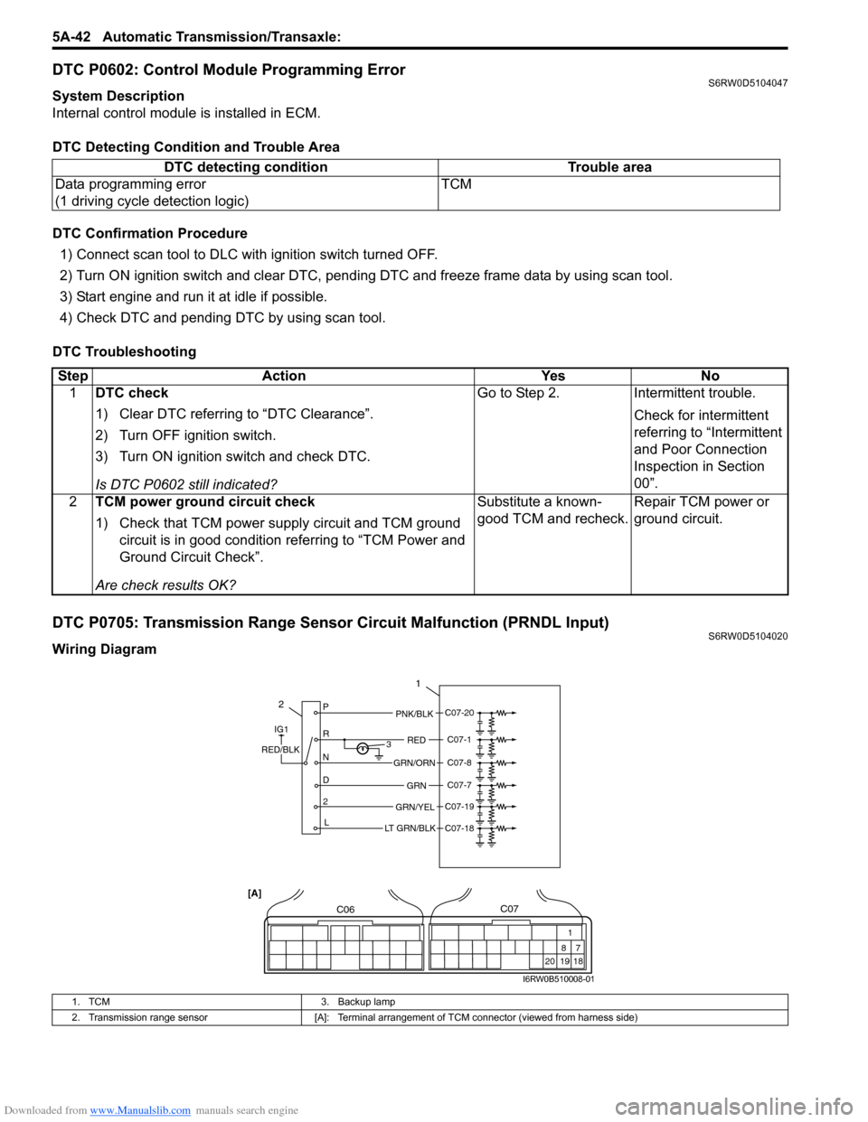
DTC P0705: Transmission Range Sensor Circuit Malfunction (PRNDL Input)S6RW0D5104020
Wiring DiagramDTC detecting condition Trouble area
Data programming error
(1 driving cycle detection logic)TCM
Step Action Yes No
1DTC check
1) Clear DTC referring to “DTC Clearance”.
2) Turn OFF ignition switch.
3) Turn ON ignition switch and check DTC.
Is DTC P0602 still indicated?Go to Step 2. Intermittent trouble.
Check for intermittent
referring to “Intermittent
and Poor Connection
Inspection in Section
00”.
2TCM power ground circuit check
1) Check that TCM power supply circuit and TCM ground
circuit is in good condition referring to “TCM Power and
Ground Circuit Check”.
Are check results OK?Substitute a known-
good TCM and recheck.Repair TCM power or
ground circuit.
2P
R
N
D
2
L3
1
PNK/BLK
RED
GRN
GRN/ORN
GRN/YEL
IG1
RED/BLK
LT GRN/BLK
C07-20
C07-1
C07-8
C07-7
C07-19
C07-18
C06
20 1987
18 1
C07
[A]
I6RW0B510008-01
1. TCM 3. Backup lamp
2. Transmission range sensor [A]: Terminal arrangement of TCM connector (viewed from harness side)
Page 699 of 1556

Downloaded from www.Manualslib.com manuals search engine Automatic Transmission/Transaxle: 5A-51
DTC P0722: Output Speed Sensor (VSS) Circuit No SignalS6RW0D5104025
Wiring Diagram
DTC Detecting Condition and Trouble Area3Inspect input shaft speed sensor
1) Inspect input shaft speed sensor referring to “Input Shaft
Speed Sensor Inspection”.
Is result satisfactory?“WHT” or “BLK” circuit
open or short.Replace input shaft
speed sensor.
4Check visually input shaft speed sensor and direct
clutch drum for the following
• No damage
• No foreign material attached
• Correct installation
Are they in good condition?Intermittent trouble or
faulty TCM.
Check for intermittent
referring to “Intermittent
and Poor Connection
Inspection in Section
00”.
If OK, substitute a
known-good TCM and
recheck.Clean, repair or replace. Step Action Yes No
I2RH0B510020-01
12 11
C06C07
[A]
112V
IG1
PPLBLK/WHT
BLK/ORNC07-25
23
I6RW0B510011-01
1. TCM 3. To ECM
2. Output shaft speed sensor (VSS) [A]: Terminal arrangement of TCM connector (viewed from harness side)
DTC detecting condition Trouble area
No output shaft speed sensor signal is detected although
input shaft speed sensor signals are detected with “D”, “2” or
“L” range.• Output shaft speed sensor or its circuit malfunction
• Damaged sensor gear (driven gear)
• Damaged output shaft speed sensor (VSS) drive
gear
•TCM
Page 707 of 1556

Downloaded from www.Manualslib.com manuals search engine Automatic Transmission/Transaxle: 5A-59
DTC Detecting Condition and Trouble Area
DTC Confirmation Procedure
1) Connect scan tool to DLC with ignition switch OFF, if available.
2) Clear DTC in TCM memory.
3) Start engine.
4) Keep engine running at idle speed for 30 seconds or more.
5) Stop vehicle and check DTC.
DTC TroubleshootingDTC detecting condition Trouble area
Difference between actual current of control solenoid valve
circuit and current of control solenoid valve circuit calculated
by ECM is more than specification.• Malfunction of pressure control solenoid valve or its
circuit malfunction
•TCM
Step Action Yes No
1Was “A/T System Check” performed?Go to Step 2. Go to “A/T System
Check”.
2Check pressure control solenoid valve resistance
1) Turn ignition switch OFF.
2) Disconnect valve body harness connector (1), (2) on
automatic transaxle.
3) Check for proper connection to terminal of valve body
harness connector at “GRY” and “LT GRN/BLK” circuit.
4) check resistance of pressure control solenoid valve.
Pressure control solenoid valve resistance
Between terminals of transaxle side valve body
harness connector: 5.0 – 5.6 Ω at 20 °C (68 °F)
Between terminals of transaxle side valve body
harness connector and transaxle: Infinity
Is check results satisfactory?Go to Step 3. Replace pressure
control solenoid valve or
valve body harness.
1
6 7 8 9
1054
32
2
1
I5RW0C510018-03
Page 717 of 1556

Downloaded from www.Manualslib.com manuals search engine Automatic Transmission/Transaxle: 5A-69
DTC Troubleshooting
DTC P1878: Torque Converter Clutch ShudderS6RW0D5104041
DTC Detecting Condition and Trouble Area
DTC Confirmation Procedure
WARNING!
• When performing a road test, select a place where there is no traffic or possibility of a traffic
accident and be very careful during testing to avoid occurrence of an accident.
• Road test should be carried out with 2 persons, a driver and tester, on a level road.
1) Connect scan tool to DLC with ignition switch OFF.
2) Clear DTCs in TCM and ECM memories by using scan tool.
3) Start engine and warm it up to normal operating temperature.
4) Drive vehicle with 3rd or 4th gear in “D” range and slip controlled lock-up ON for 20 seconds or longer referring to
“Automatic Gear Shift Table”.
5) Stop vehicle.
6) Check DTC, pending DTC and freeze-frame data.
DTC TroubleshootingStep Action Yes No
1Was “A/T System Check” performed?Go to Step 2. Go to “A/T System
Check”.
2“3” position switch circuit for operation
1) Connect SUZUKI scan tool to DLC with ignition switch
OFF.
2) Turn ignition switch ON and check “3” position switch
signal on scan tool data display when shifting select
lever to each range.
Does indicate “3” position switch condition OFF when
shifting select lever to “P”, “R”, “N” and “L” range?Substitute a known-
good TCM and recheck.Go to Step 3.
3“3” position switch signal inspection
With ignition switch ON, check voltage between “C07-9”
terminal of TCM coupler and ground.
“3” position switch specifications
Shift select lever to “3” or “2” range: Battery voltage
Shift select lever to other above range: 0 V
Is the result as specified?Substitute a known-
good BCM and recheck.Go to Step 4.
4Check “3” position switch operation
Is it in good condition?“YEL” wire shorted to
ground.Replace “3” position
switch.
DTC detecting condition Trouble area
The acceleration slip control function stops when the variation in the
output revolution speed of the specified amplitude and specified cycle
is detected within a specified period of time. When the specified
variation is not detected after the acceleration slip control stops.•Mismatching ATF
• Torque converter clutch malfunction
• Valve body
Step Action Yes No
1Was “A/T System Check” performed?Go to Step 2. Go to “A/T System
Check”.
2 Change A/T fluid referring to “A/T Fluid Change”.
Check DTC after performing “DTC Confirmation Procedure”.
Is DTC P1878 still indicated?Faulty torque converter
clutch.
Replace torque
converter.System is in good
condition.
Page 718 of 1556

Downloaded from www.Manualslib.com manuals search engine 5A-70 Automatic Transmission/Transaxle:
DTC P2762: Torque Converter Clutch (TCC) Pressure Control Solenoid Control Circuit Range /
Performance
S6RW0D5104050
Wiring Diagram
DTC Detecting Condition and Trouble Area
DTC Confirmation Procedure
1) Connect scan tool to DLC with ignition switch OFF, if available.
2) Clear DTC in TCM memory.
3) Start engine.
4) Keep engine running at idle speed for 30 seconds or more.
5) Stop vehicle and check DTC.
12V
C06-5
C06-3
WHT/BLU
WHT/BLK
3
1
2
53
C06C07
[A]
I6RW0D510007-01
1. TCM 3. A/T
2. TCC solenoid valve [A]: Terminal arrangement of TCM connector (viewed from harness side)
DTC detecting condition Trouble area
Difference between actual current of TCC solenoid valve
circuit and current of TCC solenoid valve circuit calculated by
ECM is more than specification.• TCC solenoid valve or its circuit malfunction
•TCM
Page 724 of 1556

Downloaded from www.Manualslib.com manuals search engine 5A-76 Automatic Transmission/Transaxle:
DTC U0073: Control Module Communication Bus OffS6RW0D5104051
Refer to “Troubleshooting for CAN-DTC in Section 1A”.
DTC U0100: Lost Communication with ECM / PCM “A”S6RW0D5104052
Refer to “Troubleshooting for CAN-DTC in Section 1A”.
Inspection of TCM and Its CircuitsS6RW0D5104044
TCM and its circuits can be checked at TCM wiring connectors by measuring voltage, pulse signal and resistance.
CAUTION!
TCM cannot be checked by itself, it is strictly prohibited to connect voltmeter or ohmmeter to TCM with
connector disconnected from it.
1) Remove TCM (1) from vehicle referring to “Transmission Control Module (TCM) Removal and Installation”.
2) Connect TCM connectors (2) to TCM.
3) Check voltage and/or pulse signal at each terminal of connectors connected using voltmeter (3) and oscilloscope
(4).
NOTE
• As each terminal voltage is affected by battery voltage, confirm that it is 11 V or more when ignition
switch is ON.
• Voltage with asterisk(*) cannot be measured by voltmeter because it is pulse signal. Check it with
oscilloscope if necessary.
Terminal arrangement of TCM coupler (Viewed from harness side)
3
4
12
I4RS0A510021-02
65
16 15 14 13 12 1143
24 23 212210 9 8 721
19 20 18 17 C06
17 16
26 2515 14 65 342
13 12
23 22 2411 10 9
21 20 1987
18 1 C07
I6RW0B510018-01