rear assembly SUZUKI SX4 2006 1.G Service Workshop Manual
[x] Cancel search | Manufacturer: SUZUKI, Model Year: 2006, Model line: SX4, Model: SUZUKI SX4 2006 1.GPages: 1556, PDF Size: 37.31 MB
Page 1421 of 1556

Downloaded from www.Manualslib.com manuals search engine Security and Locks: 9F-10
Rear Door Lock Assembly ComponentsS6RW0D9606007
Rear Door Lock Assembly Removal and
Installation
S6RW0D9606008
Removal
1) Remove rear door glass referring to “Rear Door
Glass Removal and Installation in Section 9E”.
2) Disconnect door lock motor lead wire (If equipped).
3) Remove door latch mounting screws (1) and remove
door latch assembly (2).
Installation
Reverse removal procedure to install rear door lock
assembly referring to the following instruction and “Front
Door Lock Assembly Removal and Installation”.• Tighten door latch screw to specified torque.
Tightening torque
Door latch screw (a): 5.0 N·m (0.5 kgf-m, 4.0 lb-ft)
• Install door trim referring to “Rear Door Glass
Removal and Installation in Section 9E”.
Rear Door Lock Assembly InspectionS6RW0D9606009
• Check that door opens and closes smoothly and
properly.
• Check that door stops in the secondary latched
position properly (preventing door from opening
freely) and that door closes completely in the fully
latched position.
• Adjust door latch striker position referring to “Front
Door Lock Assembly Removal and Installation”, if
necessary.
(a)
(b) 1
6
2
5
34
I5RW0A960006-01
1. Outside handle
: Apply lithium grease 99000-25011 to sliding part.4. Latch striker : 5.0 N⋅m
(0.5 kgf-m, 4.0 lb-ft)
2. Outside handle frame
: Apply lithium grease 99000-25011 to sliding part and spring.5. Inside handle bezel : 10 N⋅m
(1.0 kgf-m, 7.5 lb-ft)
3. Rear door latch assembly
: Apply lithium grease 99000-25011 to sliding part.6. Out side handle cap
1 2
I4RS0A960013-01
(a)
I4RS0A960014-01
Page 1422 of 1556
Downloaded from www.Manualslib.com manuals search engine 9F-11 Security and Locks:
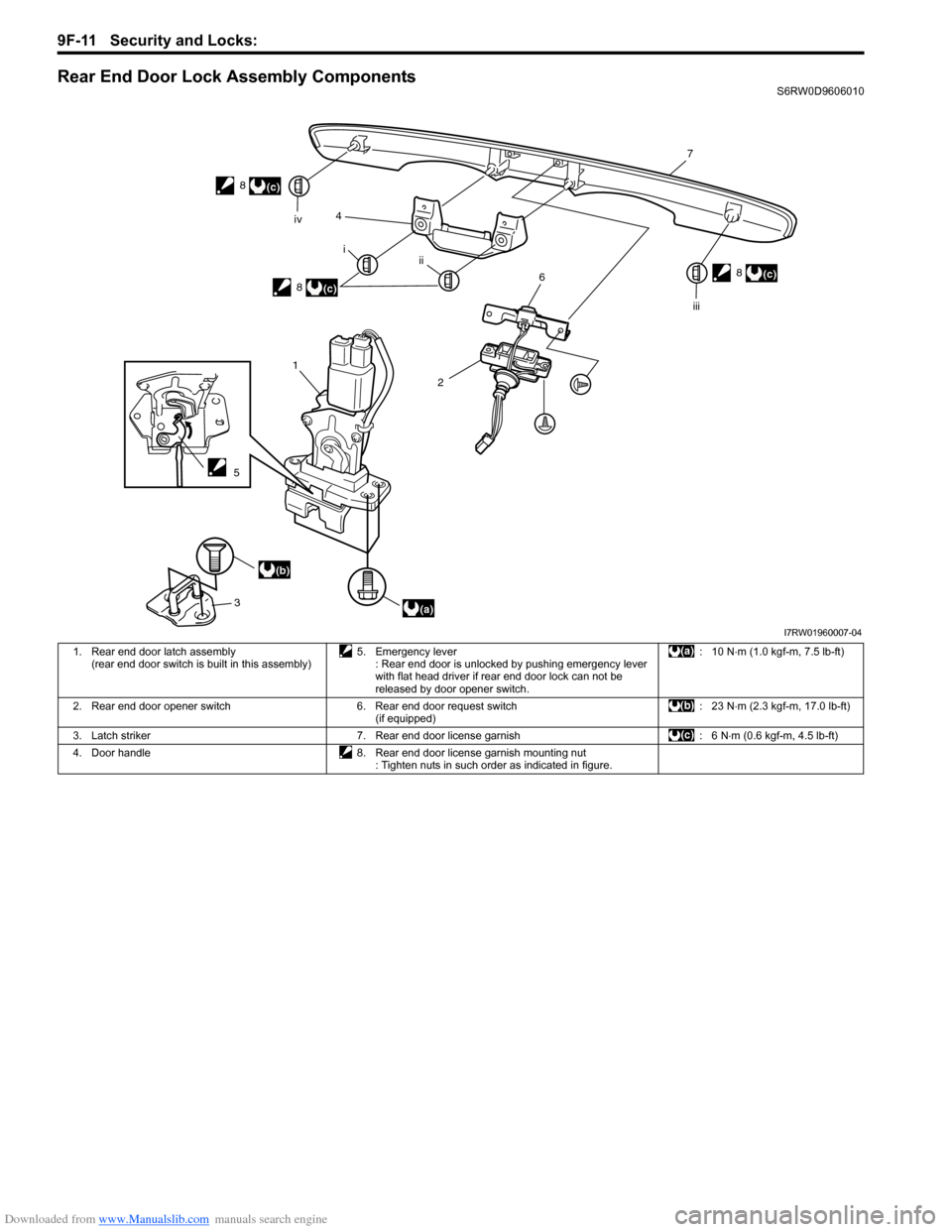
Rear End Door Lock Assembly ComponentsS6RW0D9606010
1
3
(a)
(b)4
5
2
6
7
8
i
ii iv
iii
(c)
8
(c)
8(c)
I7RW01960007-04
1. Rear end door latch assembly
(rear end door switch is built in this assembly)5. Emergency lever
: Rear end door is unlocked by pushing emergency lever
with flat head driver if rear end door lock can not be
released by door opener switch.: 10 N⋅m (1.0 kgf-m, 7.5 lb-ft)
2. Rear end door opener switch 6. Rear end door request switch
(if equipped): 23 N⋅m (2.3 kgf-m, 17.0 lb-ft)
3. Latch striker 7. Rear end door license garnish : 6 N⋅m (0.6 kgf-m, 4.5 lb-ft)
4. Door handle 8. Rear end door license garnish mounting nut
: Tighten nuts in such order as indicated in figure.
Page 1423 of 1556

Downloaded from www.Manualslib.com manuals search engine Security and Locks: 9F-12
Rear End Door Lock Assembly Removal and
Installation
S6RW0D9606011
Removal
1) Remove door trim (1) from rear end door panel (2).
2) Disconnect door lock motor lead wire (if equipped).
3) Loosen door latch bolts (1) and remove door latch
assembly (2).
Installation
Reverse removal procedure to install rear end door lock
assembly noting the following instruction.
• Tighten rear end door latch bolt to specified torque.
Tightening torque
Rear end door latch bolt (a): 10 N·m (1.0 kgf-m,
7.5 lb-ft)• Adjust door latch striker so that its center aligns with
the center of groove in door latch base.
Tightening torque
Rear end door striker screw (a): 23 N·m (2.3 kgf-
m, 17.0 lb-ft)
Rear End Door Lock Assembly InspectionS6RW0D9606012
• Check that door opens and closes smoothly and
properly.
• Check that door stops in the secondary latched
position properly (preventing door from opening
freely) and that door closes completely in the fully
latched position.
• Adjust door latch striker position referring to “Front
Door Lock Assembly Removal and Installation”, if
necessary.
Rear End Door Opener Switch Inspection (If
Equipped)
S6RW0D9606013
1) Remove rear end door trim.
2) Disconnect rear end door switch coupler.
3) Check that there is continuity between terminals “a”
and “b” when rear end door opener switch (1) is
pushed.
4) Check that there is no continuity between terminals
when rear end door opener switch (1) is not pushed.
2
1
I5RW0A960008-02
1
2
I4RS0A960017-01
(a)
I4RS0A960018-01
(a)
I4RS0A960019-01
Page 1427 of 1556
Downloaded from www.Manualslib.com manuals search engine Security and Locks: 9F-16
Specifications
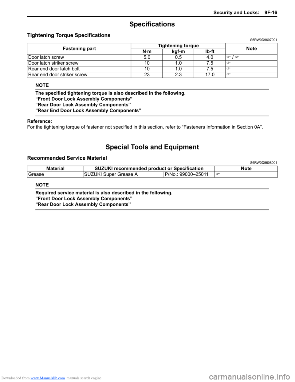
Tightening Torque SpecificationsS6RW0D9607001
NOTE
The specified tightening torque is also described in the following.
“Front Door Lock Assembly Components”
“Rear Door Lock Assembly Components”
“Rear End Door Lock Assembly Components”
Reference:
For the tightening torque of fastener not specified in this section, refer to “Fasteners Information in Section 0A”.
Special Tools and Equipment
Recommended Service MaterialS6RW0D9608001
NOTE
Required service material is also described in the following.
“Front Door Lock Assembly Components”
“Rear Door Lock Assembly Components”
Fastening partTightening torque
Note
N⋅mkgf-mlb-ft
Door latch screw 5.0 0.5 4.0�) / �)
Door latch striker screw 10 1.0 7.5�)
Rear end door latch bolt 10 1.0 7.5�)
Rear end door striker screw 23 2.3 17.0�)
Material SUZUKI recommended product or Specification Note
Grease SUZUKI Super Grease A P/No.: 99000–25011�)
Page 1431 of 1556
Downloaded from www.Manualslib.com manuals search engine Seats: 9G-4
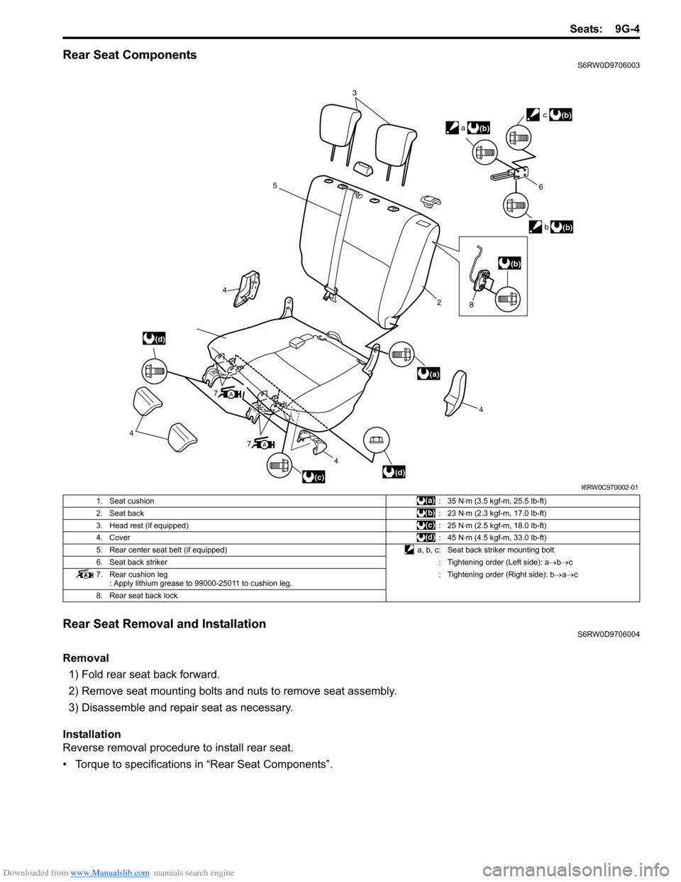
Rear Seat ComponentsS6RW0D9706003
Rear Seat Removal and InstallationS6RW0D9706004
Removal
1) Fold rear seat back forward.
2) Remove seat mounting bolts and nuts to remove seat assembly.
3) Disassemble and repair seat as necessary.
Installation
Reverse removal procedure to install rear seat.
• Torque to specifications in “Rear Seat Components”.
3
5
4
4
4
7
4
2
6
b
c
a
(d)
(a)
(d)
(b)
(b)
(b)
(c)
A
7A
(b)
8
I6RW0C970002-01
1. Seat cushion:35 N⋅m (3.5 kgf-m, 25.5 lb-ft)
2. Seat back:23 N⋅m (2.3 kgf-m, 17.0 lb-ft)
3. Head rest (if equipped):25 N⋅m (2.5 kgf-m, 18.0 lb-ft)
4. Cover:45 N⋅m (4.5 kgf-m, 33.0 lb-ft)
5. Rear center seat belt (if equipped) a, b, c: Seat back striker mounting bolt
6. Seat back striker: Tightening order (Left side): a→b→c
7. Rear cushion leg
: Apply lithium grease to 99000-25011 to cushion leg.: Tightening order (Right side): b→a→c
8. Rear seat back lock
Page 1438 of 1556
Downloaded from www.Manualslib.com manuals search engine 9J-2 Hood / Fenders / Doors:
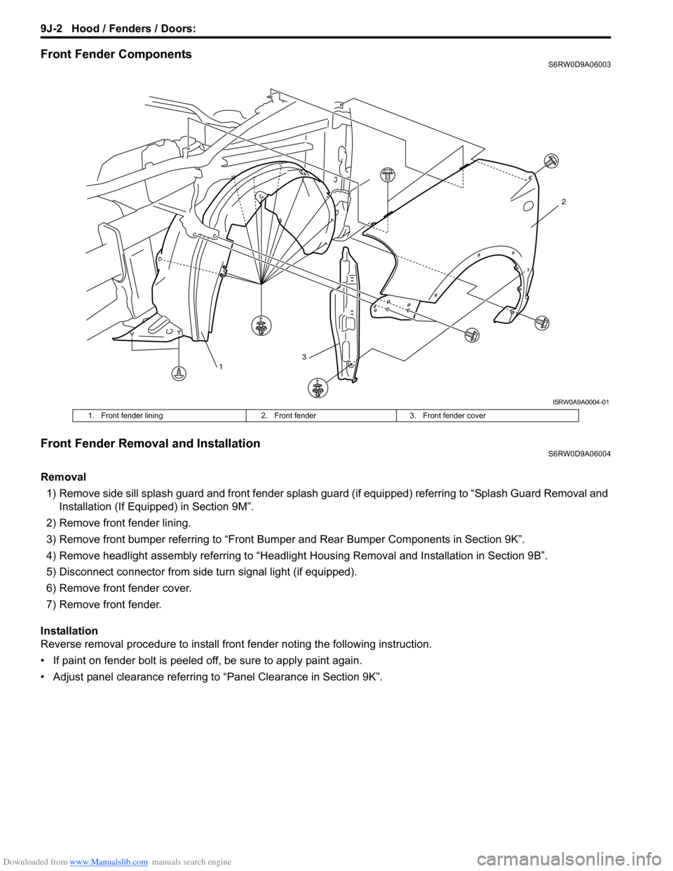
Front Fender ComponentsS6RW0D9A06003
Front Fender Removal and InstallationS6RW0D9A06004
Removal
1) Remove side sill splash guard and front fender splash guard (if equipped) referring to “Splash Guard Removal and
Installation (If Equipped) in Section 9M”.
2) Remove front fender lining.
3) Remove front bumper referring to “Front Bumper and Rear Bumper Components in Section 9K”.
4) Remove headlight assembly referring to “Headlight Housing Removal and Installation in Section 9B”.
5) Disconnect connector from side turn signal light (if equipped).
6) Remove front fender cover.
7) Remove front fender.
Installation
Reverse removal procedure to install front fender noting the following instruction.
• If paint on fender bolt is peeled off, be sure to apply paint again.
• Adjust panel clearance referring to “Panel Clearance in Section 9K”.
13
2
I5RW0A9A0004-01
1. Front fender lining 2. Front fender 3. Front fender cover
Page 1441 of 1556
Downloaded from www.Manualslib.com manuals search engine Hood / Fenders / Doors: 9J-5
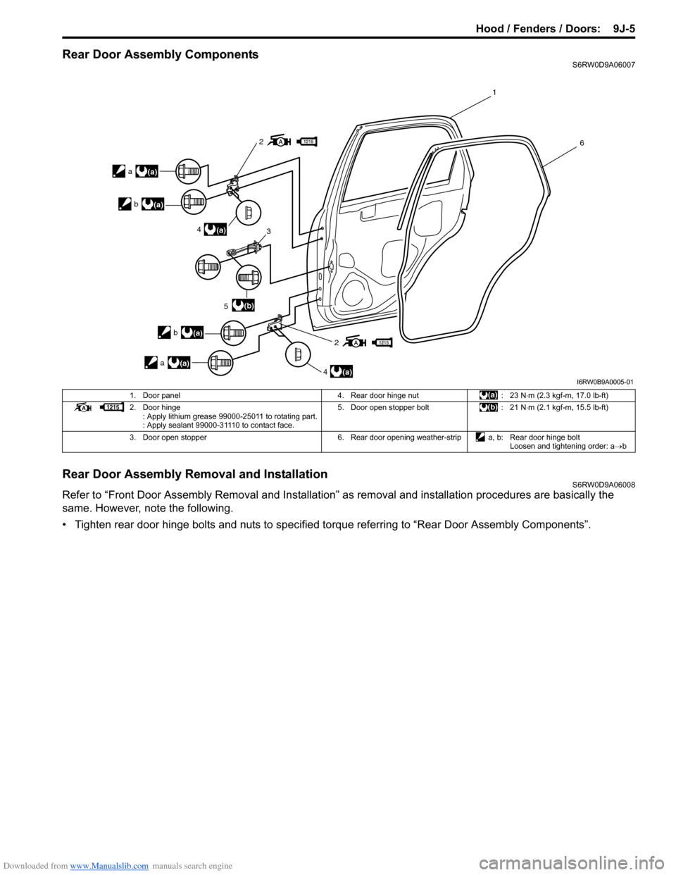
Rear Door Assembly ComponentsS6RW0D9A06007
Rear Door Assembly Removal and InstallationS6RW0D9A06008
Refer to “Front Door Assembly Removal and Installation” as removal and installation procedures are basically the
same. However, note the following.
• Tighten rear door hinge bolts and nuts to specified torque referring to “Rear Door Assembly Components”.
2
2
4
5
4 3
1
6
(a)
(a)
(b)
a(a) b
(a)
a(a)
b
(a)
I6RW0B9A0005-01
1. Door panel 4. Rear door hinge nut : 23 N⋅m (2.3 kgf-m, 17.0 lb-ft)
2. Door hinge
: Apply lithium grease 99000-25011 to rotating part.
: Apply sealant 99000-31110 to contact face.5. Door open stopper bolt : 21 N⋅m (2.1 kgf-m, 15.5 lb-ft)
3. Door open stopper 6. Rear door opening weather-strip a, b: Rear door hinge bolt
Loosen and tightening order: a→b
Page 1442 of 1556
Downloaded from www.Manualslib.com manuals search engine 9J-6 Hood / Fenders / Doors:
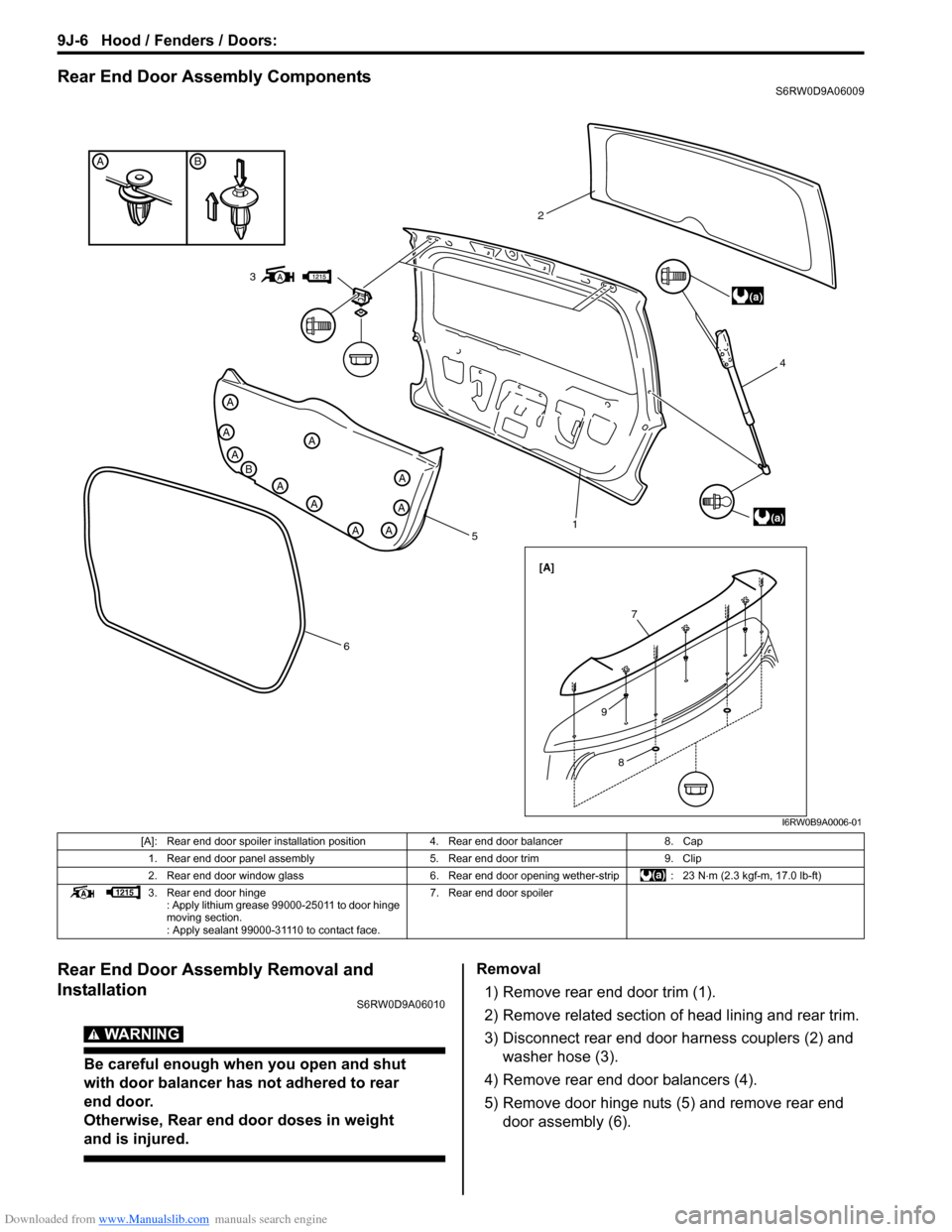
Rear End Door Assembly ComponentsS6RW0D9A06009
Rear End Door Assembly Removal and
Installation
S6RW0D9A06010
WARNING!
Be careful enough when you open and shut
with door balancer has not adhered to rear
end door.
Otherwise, Rear end door doses in weight
and is injured.
Removal
1) Remove rear end door trim (1).
2) Remove related section of head lining and rear trim.
3) Disconnect rear end door harness couplers (2) and
washer hose (3).
4) Remove rear end door balancers (4).
5) Remove door hinge nuts (5) and remove rear end
door assembly (6).
BA
A
B
A
A
A
A
A
AA
A
A
5
614 2
(a)
(a)
[A]
3
7
8
9
I6RW0B9A0006-01
[A]: Rear end door spoiler installation position 4. Rear end door balancer 8. Cap
1. Rear end door panel assembly 5. Rear end door trim 9. Clip
2. Rear end door window glass 6. Rear end door opening wether-strip : 23 N⋅m (2.3 kgf-m, 17.0 lb-ft)
3. Rear end door hinge
: Apply lithium grease 99000-25011 to door hinge
moving section.
: Apply sealant 99000-31110 to contact face.7. Rear end door spoiler
Page 1443 of 1556
Downloaded from www.Manualslib.com manuals search engine Hood / Fenders / Doors: 9J-7
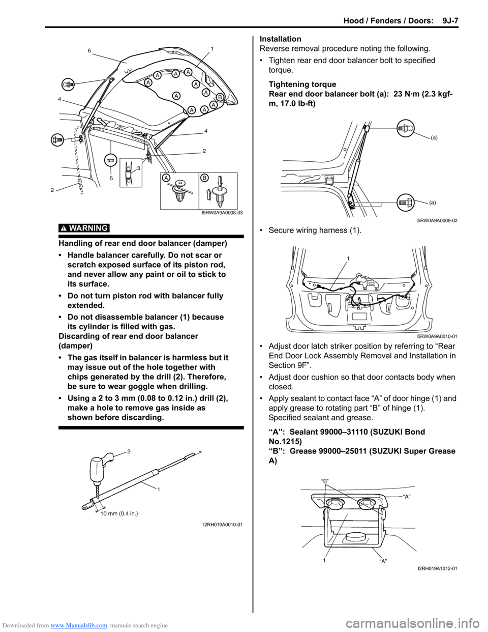
WARNING!
Handling of rear end door balancer (damper)
• Handle balancer carefully. Do not scar or
scratch exposed surface of its piston rod,
and never allow any paint or oil to stick to
its surface.
• Do not turn piston rod with balancer fully
extended.
• Do not disassemble balancer (1) because
its cylinder is filled with gas.
Discarding of rear end door balancer
(damper)
• The gas itself in balancer is harmless but it
may issue out of the hole together with
chips generated by the drill (2). Therefore,
be sure to wear goggle when drilling.
• Using a 2 to 3 mm (0.08 to 0.12 in.) drill (2),
make a hole to remove gas inside as
shown before discarding.
Installation
Reverse removal procedure noting the following.
• Tighten rear end door balancer bolt to specified
torque.
Tightening torque
Rear end door balancer bolt (a): 23 N·m (2.3 kgf-
m, 17.0 lb-ft)
• Secure wiring harness (1).
• Adjust door latch striker position by referring to “Rear
End Door Lock Assembly Removal and Installation in
Section 9F”.
• Adjust door cushion so that door contacts body when
closed.
• Apply sealant to contact face “A” of door hinge (1) and
apply grease to rotating part “B” of hinge (1).
Specified sealant and grease.
“A”: Sealant 99000–31110 (SUZUKI Bond
No.1215)
“B”: Grease 99000–25011 (SUZUKI Super Grease
A)
AB
A
A
A
A
AAA
AAA
B
3
5
461
4
2
2
I5RW0A9A0008-03
I2RH019A0010-01
(a)
(a)
I5RW0A9A0009-02
1
I5RW0A9A0010-01
I2RH019A1012-01
Page 1444 of 1556
Downloaded from www.Manualslib.com manuals search engine 9J-8 Hood / Fenders / Doors:
Specifications
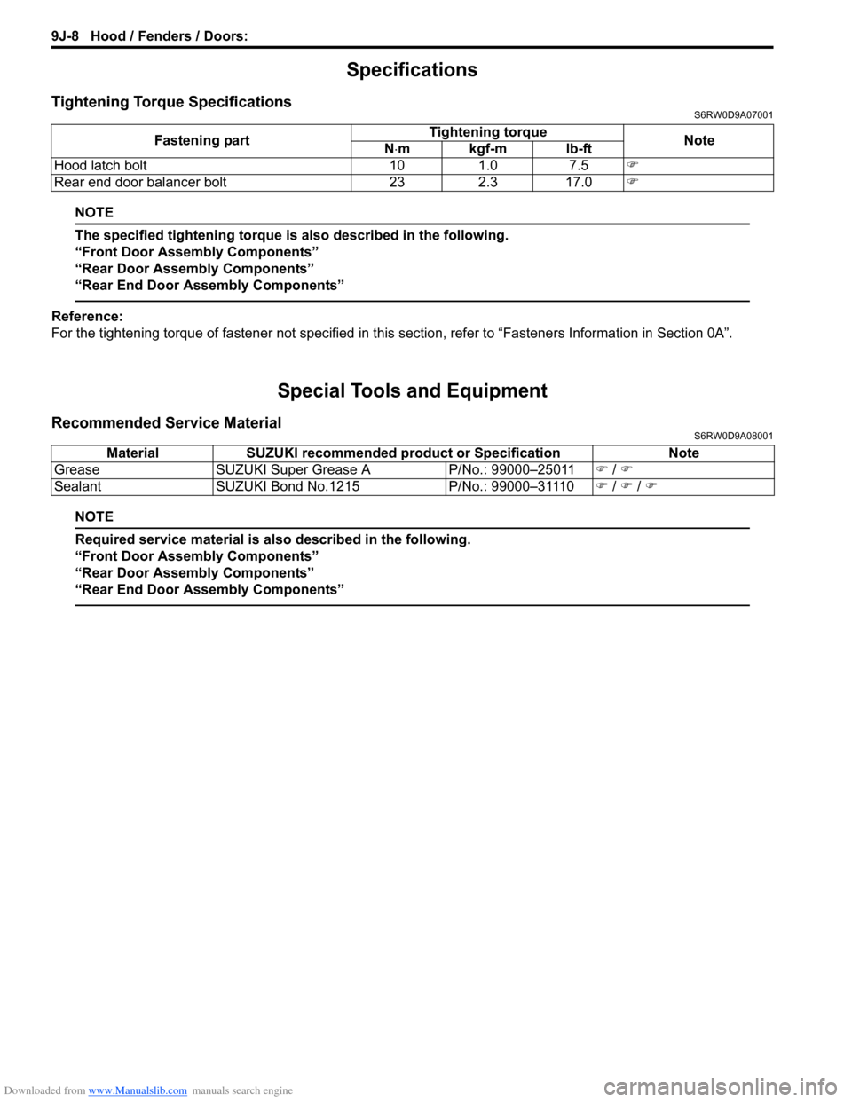
Tightening Torque SpecificationsS6RW0D9A07001
NOTE
The specified tightening torque is also described in the following.
“Front Door Assembly Components”
“Rear Door Assembly Components”
“Rear End Door Assembly Components”
Reference:
For the tightening torque of fastener not specified in this section, refer to “Fasteners Information in Section 0A”.
Special Tools and Equipment
Recommended Service MaterialS6RW0D9A08001
NOTE
Required service material is also described in the following.
“Front Door Assembly Components”
“Rear Door Assembly Components”
“Rear End Door Assembly Components”
Fastening partTightening torque
Note
N⋅mkgf-mlb-ft
Hood latch bolt 10 1.0 7.5�)
Rear end door balancer bolt 23 2.3 17.0�)
Material SUZUKI recommended product or Specification Note
Grease SUZUKI Super Grease A P/No.: 99000–25011�) / �)
Sealant SUZUKI Bond No.1215 P/No.: 99000–31110�) / �) / �)