rear assembly SUZUKI SX4 2006 1.G Service Workshop Manual
[x] Cancel search | Manufacturer: SUZUKI, Model Year: 2006, Model line: SX4, Model: SUZUKI SX4 2006 1.GPages: 1556, PDF Size: 37.31 MB
Page 1346 of 1556
Downloaded from www.Manualslib.com manuals search engine 9B-27 Lighting Systems:
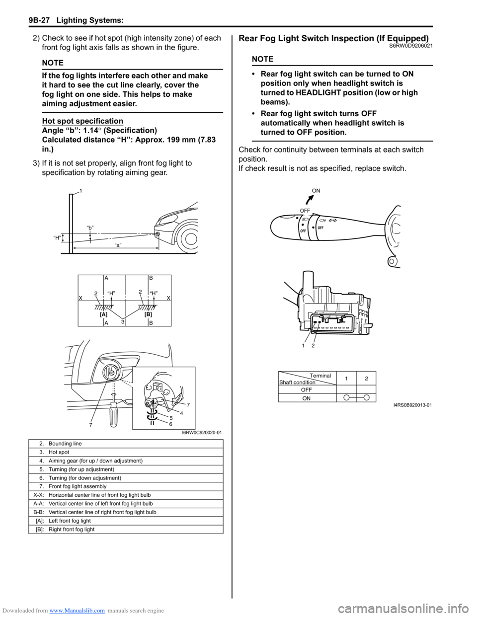
2) Check to see if hot spot (high intensity zone) of each
front fog light axis falls as shown in the figure.
NOTE
If the fog lights interfere each other and make
it hard to see the cut line clearly, cover the
fog light on one side. This helps to make
aiming adjustment easier.
Hot spot specification
Angle “b”: 1.14° (Specification)
Calculated distance “H”: Approx. 199 mm (7.83
in.)
3) If it is not set properly, align front fog light to
specification by rotating aiming gear.
Rear Fog Light Switch Inspection (If Equipped)S6RW0D9206021
NOTE
• Rear fog light switch can be turned to ON
position only when headlight switch is
turned to HEADLIGHT position (low or high
beams).
• Rear fog light switch turns OFF
automatically when headlight switch is
turned to OFF position.
Check for continuity between terminals at each switch
position.
If check result is not as specified, replace switch.
2. Bounding line
3. Hot spot
4. Aiming gear (for up / down adjustment)
5. Turning (for up adjustment)
6. Turning (for down adjustment)
7. Front fog light assembly
X-X: Horizontal center line of front fog light bulb
A-A: Vertical center line of left front fog light bulb
B-B: Vertical center line of right front fog light bulb
[A]: Left front fog light
[B]: Right front fog light
32
2
AB AB
[A] [B]X X
1
“H”
“H” “H” “b”
“a”
54
7
67I6RW0C920020-01
Terminal
Shaft condition12
OFF
ON
ON
OFF
2 1
I4RS0B920013-01
Page 1357 of 1556
Downloaded from www.Manualslib.com manuals search engine Instrumentation / Driver Info. / Horn: 9C-5
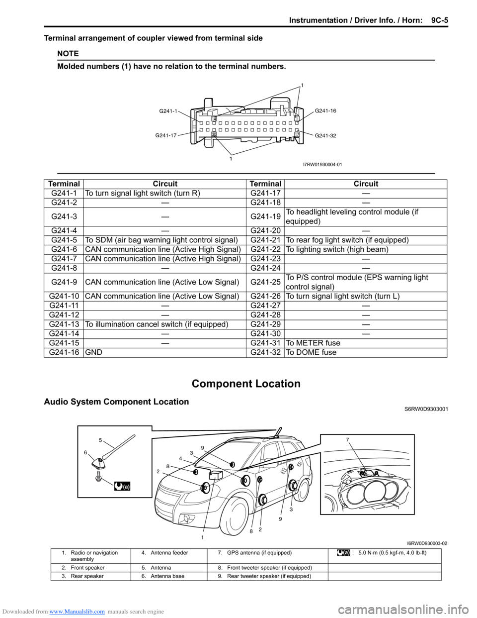
Terminal arrangement of coupler viewed from terminal side
NOTE
Molded numbers (1) have no relation to the terminal numbers.
Component Location
Audio System Component LocationS6RW0D9303001
Terminal Circuit Terminal Circuit
G241-1 To turn signal light switch (turn R) G241-17 —
G241-2 — G241-18 —
G241-3 — G241-19To headlight leveling control module (if
equipped)
G241-4 — G241-20 —
G241-5 To SDM (air bag warning light control signal) G241-21 To rear fog light switch (if equipped)
G241-6 CAN communication line (Active High Signal) G241-22 To lighting switch (high beam)
G241-7 CAN communication line (Active High Signal) G241-23 —
G241-8 — G241-24 —
G241-9 CAN communication line (Active Low Signal) G241-25To P/S control module (EPS warning light
control signal)
G241-10 CAN communication line (Active Low Signal) G241-26 To turn signal light switch (turn L)
G241-11 — G241-27 —
G241-12 — G241-28 —
G241-13 To illumination cancel switch (if equipped) G241-29 —
G241-14 — G241-30 —
G241-15 — G241-31 To METER fuse
G241-16 GND G241-32 To DOME fuse
G241-1G241-16
G241-32 G241-17
11I7RW01930004-01
3
2
3
2
1
4
8
8
9
96
5
(a)
7
I6RW0D930003-02
1. Radio or navigation
assembly4. Antenna feeder 7. GPS antenna (if equipped) : 5.0 N⋅m (0.5 kgf-m, 4.0 lb-ft)
2. Front speaker 5. Antenna 8. Front tweeter speaker (if equipped)
3. Rear speaker 6. Antenna base 9. Rear tweeter speaker (if equipped)
Page 1377 of 1556
Downloaded from www.Manualslib.com manuals search engine Wipers / Washers: 9D-3
Washer Tank and Washer Pump Removal and
Installation
S6RW0D9406002
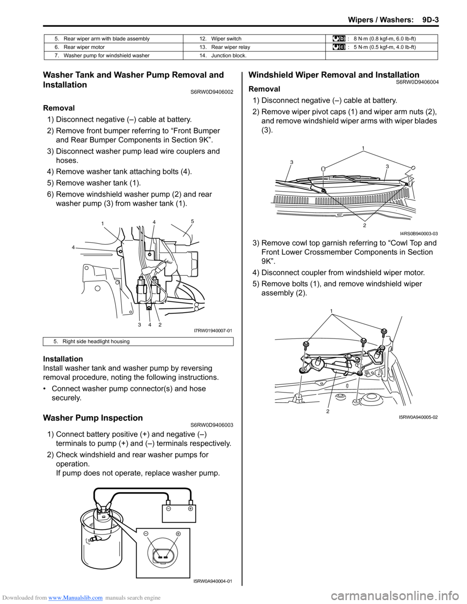
Removal
1) Disconnect negative (–) cable at battery.
2) Remove front bumper referring to “Front Bumper
and Rear Bumper Components in Section 9K”.
3) Disconnect washer pump lead wire couplers and
hoses.
4) Remove washer tank attaching bolts (4).
5) Remove washer tank (1).
6) Remove windshield washer pump (2) and rear
washer pump (3) from washer tank (1).
Installation
Install washer tank and washer pump by reversing
removal procedure, noting the following instructions.
• Connect washer pump connector(s) and hose
securely.
Washer Pump InspectionS6RW0D9406003
1) Connect battery positive (+) and negative (–)
terminals to pump (+) and (–) terminals respectively.
2) Check windshield and rear washer pumps for
operation.
If pump does not operate, replace washer pump.
Windshield Wiper Removal and InstallationS6RW0D9406004
Removal
1) Disconnect negative (–) cable at battery.
2) Remove wiper pivot caps (1) and wiper arm nuts (2),
and remove windshield wiper arms with wiper blades
(3).
3) Remove cowl top garnish referring to “Cowl Top and
Front Lower Crossmember Components in Section
9K”.
4) Disconnect coupler from windshield wiper motor.
5) Remove bolts (1), and remove windshield wiper
assembly (2).
5. Rear wiper arm with blade assembly 12. Wiper switch : 8 N⋅m (0.8 kgf-m, 6.0 lb-ft)
6. Rear wiper motor 13. Rear wiper relay : 5 N⋅m (0.5 kgf-m, 4.0 lb-ft)
7. Washer pump for windshield washer 14. Junction block.
5. Right side headlight housing
1
4
34245
I7RW01940007-01
I5RW0A940004-01
1
3 3
2
I4RS0B940003-03
21I5RW0A940005-02
Page 1380 of 1556
Downloaded from www.Manualslib.com manuals search engine 9D-6 Wipers / Washers:
Rear Wiper Removal and InstallationS6RW0D9406006
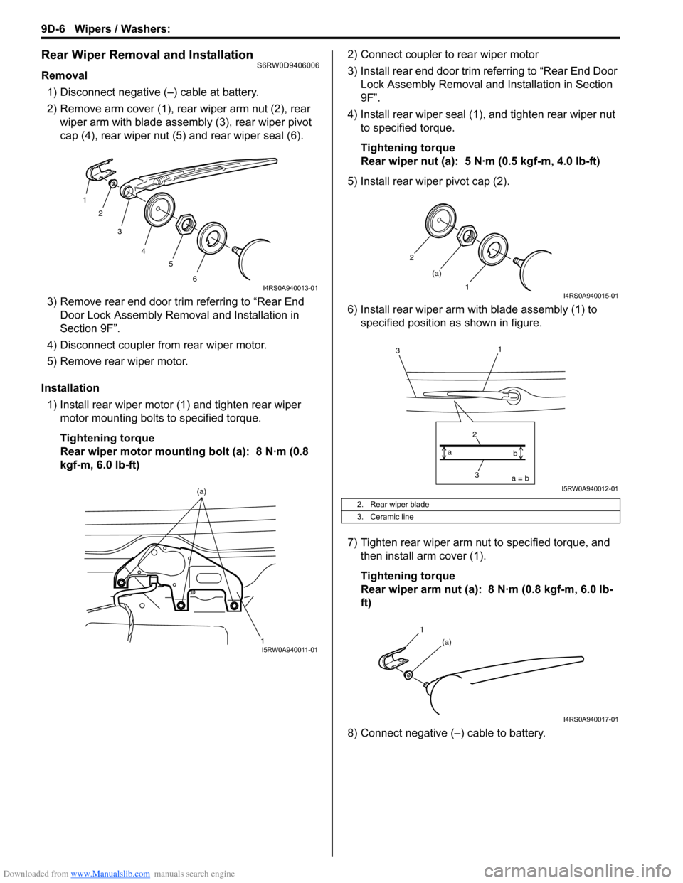
Removal
1) Disconnect negative (–) cable at battery.
2) Remove arm cover (1), rear wiper arm nut (2), rear
wiper arm with blade assembly (3), rear wiper pivot
cap (4), rear wiper nut (5) and rear wiper seal (6).
3) Remove rear end door trim referring to “Rear End
Door Lock Assembly Removal and Installation in
Section 9F”.
4) Disconnect coupler from rear wiper motor.
5) Remove rear wiper motor.
Installation
1) Install rear wiper motor (1) and tighten rear wiper
motor mounting bolts to specified torque.
Tightening torque
Rear wiper motor mounting bolt (a): 8 N·m (0.8
kgf-m, 6.0 lb-ft)2) Connect coupler to rear wiper motor
3) Install rear end door trim referring to “Rear End Door
Lock Assembly Removal and Installation in Section
9F”.
4) Install rear wiper seal (1), and tighten rear wiper nut
to specified torque.
Tightening torque
Rear wiper nut (a): 5 N·m (0.5 kgf-m, 4.0 lb-ft)
5) Install rear wiper pivot cap (2).
6) Install rear wiper arm with blade assembly (1) to
specified position as shown in figure.
7) Tighten rear wiper arm nut to specified torque, and
then install arm cover (1).
Tightening torque
Rear wiper arm nut (a): 8 N·m (0.8 kgf-m, 6.0 lb-
ft)
8) Connect negative (–) cable to battery.
1
2
3
4
5
6
I4RS0A940013-01
1 (a)I5RW0A940011-01
2. Rear wiper blade
3. Ceramic line
2
1 (a)
I4RS0A940015-01
3 2a = b a
b
1
3
I5RW0A940012-01
1
(a)
I4RS0A940017-01
Page 1382 of 1556
Downloaded from www.Manualslib.com manuals search engine 9D-8 Wipers / Washers:
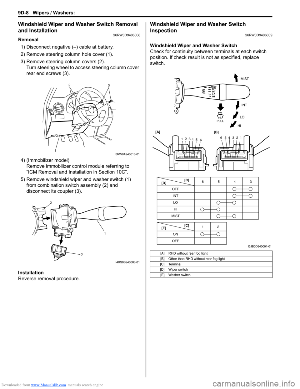
Windshield Wiper and Washer Switch Removal
and Installation
S6RW0D9406008
Removal
1) Disconnect negative (–) cable at battery.
2) Remove steering column hole cover (1).
3) Remove steering column covers (2).
Turn steering wheel to access steering column cover
rear end screws (3).
4) (Immobilizer model)
Remove immobilizer control module referring to
“ICM Removal and Installation in Section 10C”.
5) Remove windshield wiper and washer switch (1)
from combination switch assembly (2) and
disconnect its coupler (3).
Installation
Reverse removal procedure.
Windshield Wiper and Washer Switch
Inspection
S6RW0D9406009
Windshield Wiper and Washer Switch
Check for continuity between terminals at each switch
position. If check result is not as specified, replace
switch.
12
3I5RW0A940016-01
1 2
3
I4RS0B940008-01
[A]: RHD without rear fog light
[B]: Other than RHD without rear fog light
[C]: Terminal
[D]: Wiper switch
[E]: Washer switch
OFF
INT6543
MIST
OFF12
ONLO
HI
65432112
3
4
5
6 [A]
[B]
[C]
[D]
[E][C]
I5JB0D940001-01
Page 1398 of 1556
Downloaded from www.Manualslib.com manuals search engine 9E-13 Glass / Windows / Mirrors:
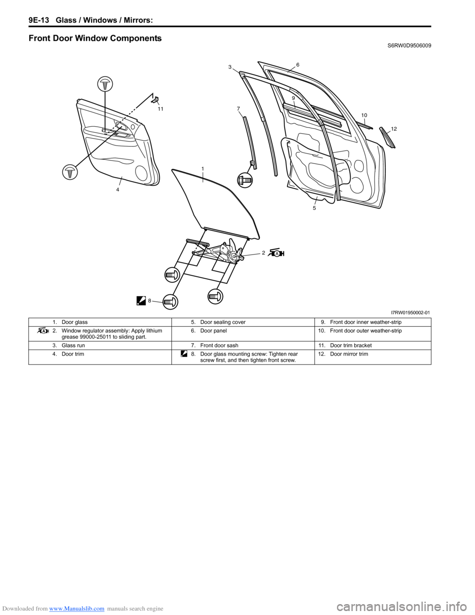
Front Door Window ComponentsS6RW0D9506009
2
8
11
4
1
7
36
9
10
12
5
I7RW01950002-01
1. Door glass 5. Door sealing cover 9. Front door inner weather-strip
2. Window regulator assembly: Apply lithium
grease 99000-25011 to sliding part.6. Door panel 10. Front door outer weather-strip
3. Glass run 7. Front door sash 11. Door trim bracket
4. Door trim 8. Door glass mounting screw: Tighten rear
screw first, and then tighten front screw.12. Door mirror trim
Page 1401 of 1556
Downloaded from www.Manualslib.com manuals search engine Glass / Windows / Mirrors: 9E-16
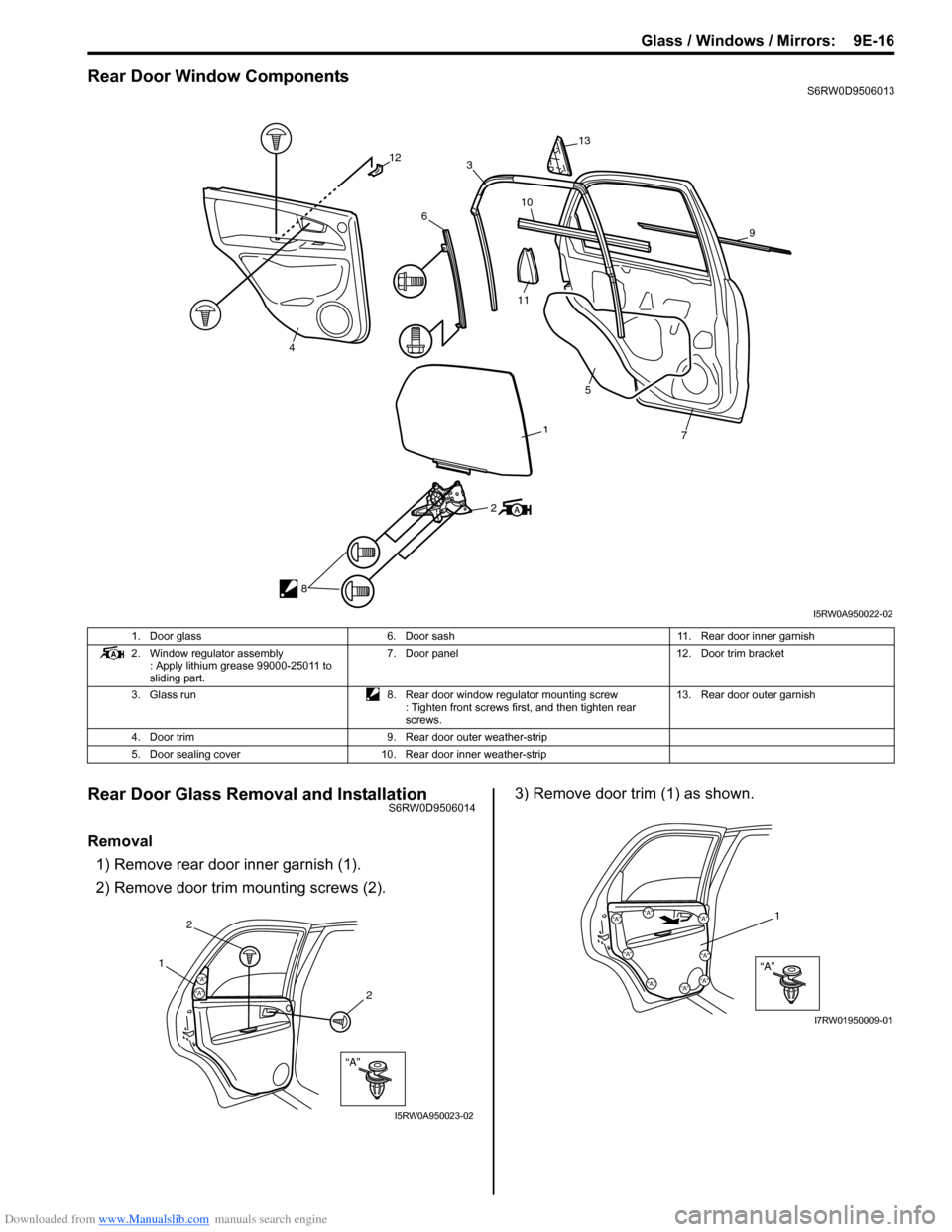
Rear Door Window ComponentsS6RW0D9506013
Rear Door Glass Removal and InstallationS6RW0D9506014
Removal
1) Remove rear door inner garnish (1).
2) Remove door trim mounting screws (2).3) Remove door trim (1) as shown.
2
8
12
4
6
3
13
10
11
9
7
5
1
I5RW0A950022-02
1. Door glass 6. Door sash 11. Rear door inner garnish
2. Window regulator assembly
: Apply lithium grease 99000-25011 to
sliding part.7. Door panel 12. Door trim bracket
3. Glass run 8. Rear door window regulator mounting screw
: Tighten front screws first, and then tighten rear
screws.13. Rear door outer garnish
4. Door trim 9. Rear door outer weather-strip
5. Door sealing cover 10. Rear door inner weather-strip
“A”
“A”“A”
2
1
2
I5RW0A950023-02
“A”
“A”
“A”“A”“A”
“A”
“A”“A”
“A”
1
I7RW01950009-01
Page 1412 of 1556
Downloaded from www.Manualslib.com manuals search engine 9F-1 Security and Locks:
Body, Cab and Accessories
Security and Locks
General Description
Key Coding ConstructionS6RW0D9601001
Key Usage and Identification
Key is used for ignition and door lock cylinders. Key is cut on both edges to make them reversible.
Key identification is obtained from five character key code stamped on key code tag. Using this key code, key code
cutting combination can be determined from a code list (available to owners of key cutting equipment from suppliers).
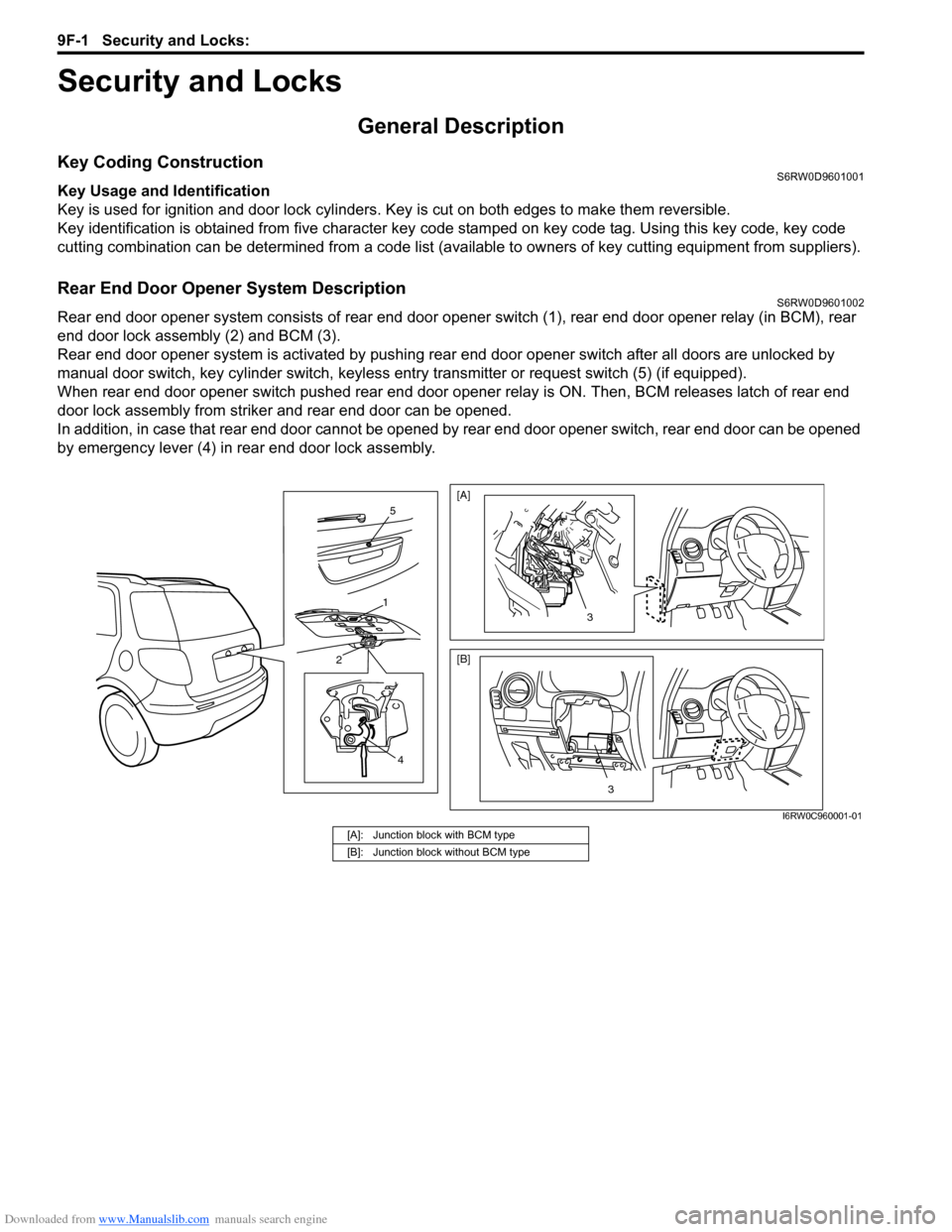
Rear End Door Opener System DescriptionS6RW0D9601002
Rear end door opener system consists of rear end door opener switch (1), rear end door opener relay (in BCM), rear
end door lock assembly (2) and BCM (3).
Rear end door opener system is activated by pushing rear end door opener switch after all doors are unlocked by
manual door switch, key cylinder switch, keyless entry transmitter or request switch (5) (if equipped).
When rear end door opener switch pushed rear end door opener relay is ON. Then, BCM releases latch of rear end
door lock assembly from striker and rear end door can be opened.
In addition, in case that rear end door cannot be opened by rear end door opener switch, rear end door can be opened
by emergency lever (4) in rear end door lock assembly.
4
2
1
5
3
[A]
[B]
3
I6RW0C960001-01
[A]: Junction block with BCM type
[B]: Junction block without BCM type
Page 1418 of 1556
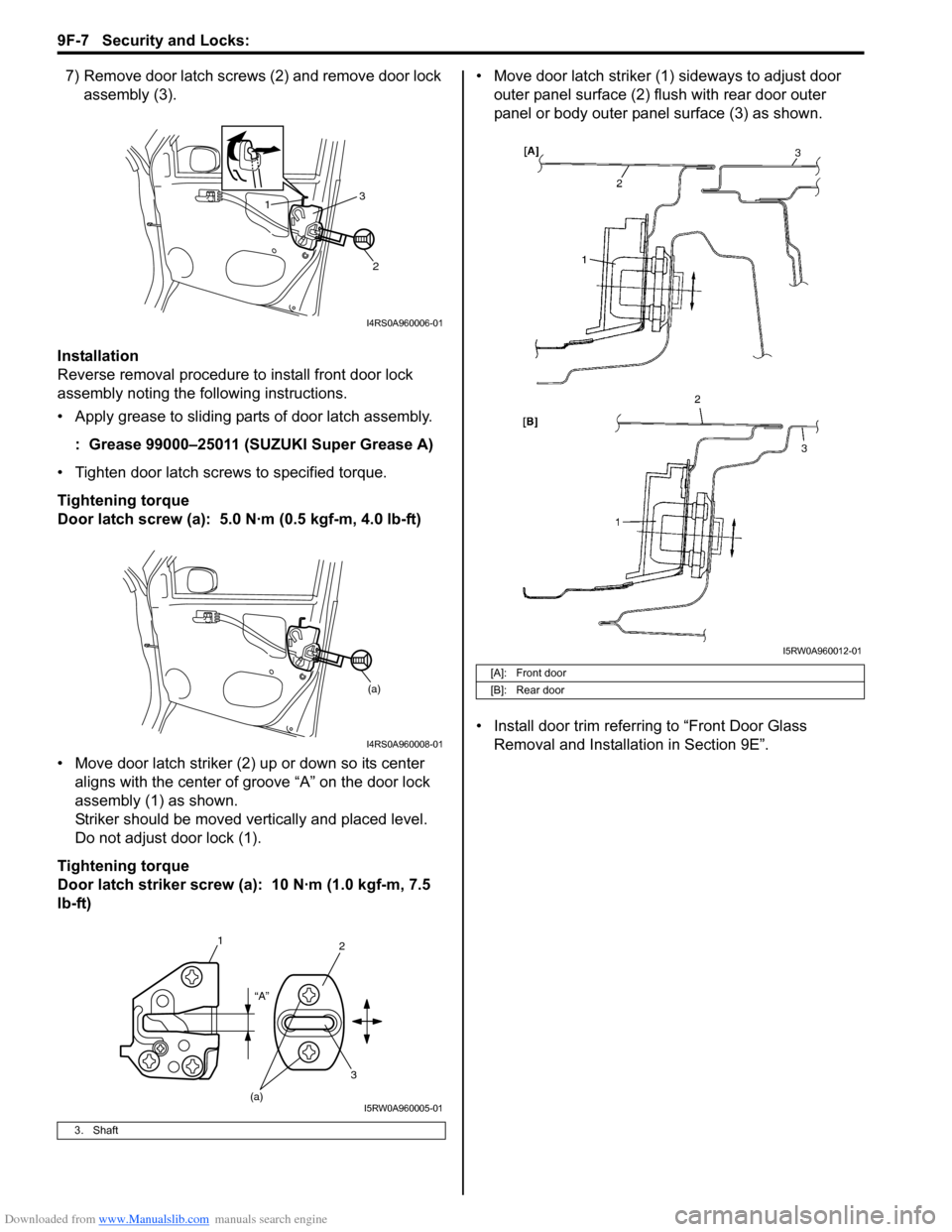
Downloaded from www.Manualslib.com manuals search engine 9F-7 Security and Locks:
7) Remove door latch screws (2) and remove door lock
assembly (3).
Installation
Reverse removal procedure to install front door lock
assembly noting the following instructions.
• Apply grease to sliding parts of door latch assembly.
: Grease 99000–25011 (SUZUKI Super Grease A)
• Tighten door latch screws to specified torque.
Tightening torque
Door latch screw (a): 5.0 N·m (0.5 kgf-m, 4.0 lb-ft)
• Move door latch striker (2) up or down so its center
aligns with the center of groove “A” on the door lock
assembly (1) as shown.
Striker should be moved vertically and placed level.
Do not adjust door lock (1).
Tightening torque
Door latch striker screw (a): 10 N·m (1.0 kgf-m, 7.5
lb-ft)• Move door latch striker (1) sideways to adjust door
outer panel surface (2) flush with rear door outer
panel or body outer panel surface (3) as shown.
• Install door trim referring to “Front Door Glass
Removal and Installation in Section 9E”.
3. Shaft
1
2 3
I4RS0A960006-01
(a)
I4RS0A960008-01
1
2
3
(a)“A”
I5RW0A960005-01
[A]: Front door
[B]: Rear door
I5RW0A960012-01
Page 1420 of 1556
Downloaded from www.Manualslib.com manuals search engine 9F-9 Security and Locks:
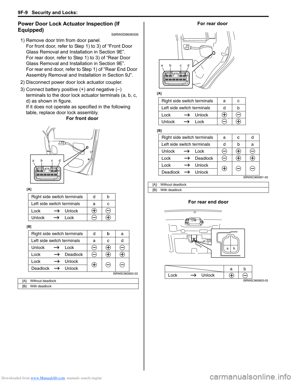
Power Door Lock Actuator Inspection (If
Equipped)
S6RW0D9606006
1) Remove door trim from door panel.
For front door, refer to Step 1) to 3) of “Front Door
Glass Removal and Installation in Section 9E”.
For rear door, refer to Step 1) to 3) of “Rear Door
Glass Removal and Installation in Section 9E”.
For rear end door, refer to Step 1) of “Rear End Door
Assembly Removal and Installation in Section 9J”.
2) Disconnect power door lock actuator coupler.
3) Connect battery positive (+) and negative (–)
terminals to the door lock actuator terminals (a, b, c,
d) as shown in figure.
If it does not operate as specified in the following
table, replace door lock assembly.
For front doorFor rear door
For rear end door
[A]: Without deadlock
[B]: With deadlock
ab cd
Right side switch terminals b
Unlock Lock
Lock Deadlock
Lock Unlock
Left side switch terminals c
Unlock
Deadlock
[A]
[B]
Right side switch terminals bd
Unlock Lock
Lock Unlock
Left side switch terminals ca
acd dba
I5RW0C960002-03
[A]: Without deadlock
[B]: With deadlock
ab cd
Right side switch terminals c
Unlock Lock
Lock Deadlock
Lock Unlock
Left side switch terminals b
Unlock
Deadlock
[B] [A]
Right side switch terminals
b d
Unlock Lock
Lock Unlock
Left side switch terminalsc a
dba acd
I5RW0C960001-03
ab
Lock Unlock
a
b
I5RW0C960003-03