AIR SUZUKI SX4 2006 1.G Service Workshop Manual
[x] Cancel search | Manufacturer: SUZUKI, Model Year: 2006, Model line: SX4, Model: SUZUKI SX4 2006 1.GPages: 1556, PDF Size: 37.31 MB
Page 457 of 1556
Downloaded from www.Manualslib.com manuals search engine Front Suspension: 2B-20
12) Install exhaust No.1, No.2 and center pipe referring
to “Exhaust System Components in Section 1K”.
13) Install wheel and tighten nut to specified torque.
Tightening torque
Wheel nut: 85 N·m (8.5 kgf-m, 61.5 lb-ft)
14) Install air cleaner assembly referring to “Air Cleaner
Assembly Removal and Installation in Section 1D”.
15) Install hood referring to “Hood Removal and
Installation in Section 9J”.
16) Lower hoist and vehicle in unloaded condition,
tighten suspension control arm bolts to specified
torque.
Tightening torque
Suspension control arm bolt: 95 N·m (9.5 kgf-m,
69.0 lb-ft)
17) Connect negative (–) cable at battery.
18) Confirm front wheel alignment referring to “Front
Wheel Alignment Inspection and Adjustment”.
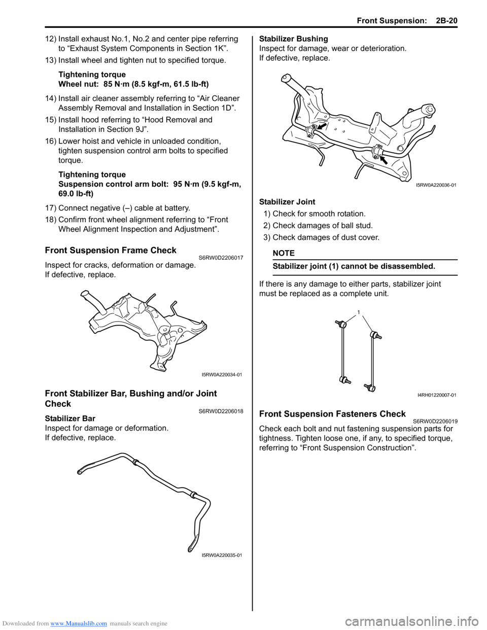
Front Suspension Frame CheckS6RW0D2206017
Inspect for cracks, deformation or damage.
If defective, replace.
Front Stabilizer Bar, Bushing and/or Joint
Check
S6RW0D2206018
Stabilizer Bar
Inspect for damage or deformation.
If defective, replace.Stabilizer Bushing
Inspect for damage, wear or deterioration.
If defective, replace.
Stabilizer Joint
1) Check for smooth rotation.
2) Check damages of ball stud.
3) Check damages of dust cover.
NOTE
Stabilizer joint (1) cannot be disassembled.
If there is any damage to either parts, stabilizer joint
must be replaced as a complete unit.
Front Suspension Fasteners CheckS6RW0D2206019
Check each bolt and nut fastening suspension parts for
tightness. Tighten loose one, if any, to specified torque,
referring to “Front Suspension Construction”.
I5RW0A220034-01
I5RW0A220035-01
I5RW0A220036-01
1
I4RH01220007-01
Page 460 of 1556
Downloaded from www.Manualslib.com manuals search engine 2C-1 Rear Suspension:
Suspension
Rear Suspension
Repair Instructions
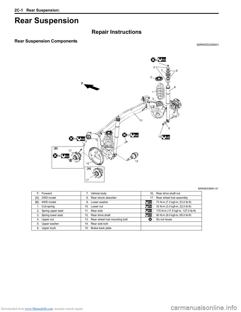
Rear Suspension ComponentsS6RW0D2306001
I6RW0D230001-01
F: Forward 7. Vehicle body 16. Rear drive shaft nut
[A]: 2WD model 8. Rear shock absorber 17. Rear wheel hub assembly
[B]: 4WD model 9. Lower washer : 73 N⋅m (7.3 kgf-m, 53.0 lb-ft)
1. Coil spring 10. Lower nut : 30 N⋅m (3.0 kgf-m, 22.0 lb-ft)
2. Spring upper seat 11. Rear axle : 175 N⋅m (17.5 kgf-m, 127.0 lb-ft)
3. Spring lower seat 12. Rear drive shaft : 90 N⋅m (9.0 kgf-m, 65.0 lb-ft)
4. Upper nut 13. Rear wheel hub mounting bolt : Do not reuse.
5. Upper washer 14. Rear axle bolt
6. Upper bush 15. Brake back plate
Page 466 of 1556
Downloaded from www.Manualslib.com manuals search engine 2C-7 Rear Suspension:
6) Connect rear height sensor link (if equipped) to rear
axle referring to “Height Sensor Removal and
Installation (If Equipped) in Section 9B”.
7) Install exhaust center pipe and muffler.
8) After installing removed parts, bleed air from brake
system referring to “Air Bleeding of Brake System in
Section 4A”. And then adjust parking brake cable
referring to “Parking Brake Inspection and
Adjustment in Section 4D”.
9) Install wheel and tighten wheel nuts to specified
torque.
Tightening torque
Wheel nut: 85 N·m (8.5 kgf-m, 61.5 lb-ft)
10) Lower hoist and bounce vehicle up and down
several times to stabilize suspension.
11) Tightening shock absorber lower nuts and rear axle
bolts to specified torque.
NOTE
When tightening these nuts and bolts, be
sure that vehicle is not on hoist and in
unloaded condition.
Tightening torque
Rear shock absorber lower nut: 90 N·m (9.0 kgf-
m, 65.0 lb-ft)
Rear axle bolt: 73 N·m (7.3 kgf-m, 53.0 lb-ft)
12) Perform brake test (foot brake and parking brake).
13) Check each installed parts for brake fluid leakage.
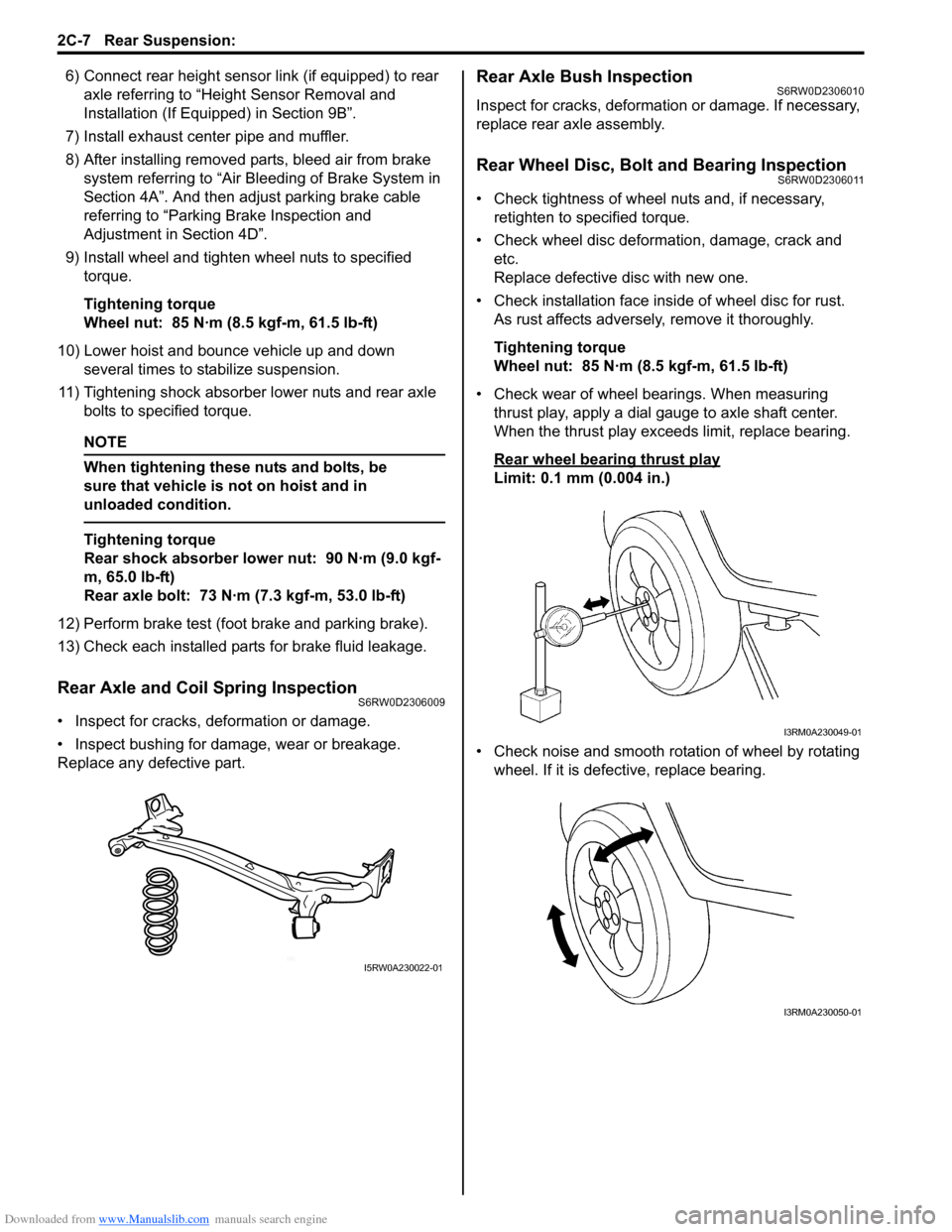
Rear Axle and Coil Spring InspectionS6RW0D2306009
• Inspect for cracks, deformation or damage.
• Inspect bushing for damage, wear or breakage.
Replace any defective part.
Rear Axle Bush InspectionS6RW0D2306010
Inspect for cracks, deformation or damage. If necessary,
replace rear axle assembly.
Rear Wheel Disc, Bolt and Bearing InspectionS6RW0D2306011
• Check tightness of wheel nuts and, if necessary,
retighten to specified torque.
• Check wheel disc deformation, damage, crack and
etc.
Replace defective disc with new one.
• Check installation face inside of wheel disc for rust.
As rust affects adversely, remove it thoroughly.
Tightening torque
Wheel nut: 85 N·m (8.5 kgf-m, 61.5 lb-ft)
• Check wear of wheel bearings. When measuring
thrust play, apply a dial gauge to axle shaft center.
When the thrust play exceeds limit, replace bearing.
Rear wheel bearing thrust play
Limit: 0.1 mm (0.004 in.)
• Check noise and smooth rotation of wheel by rotating
wheel. If it is defective, replace bearing.
(a)I5RW0A230022-01
I3RM0A230049-01
I3RM0A230050-01
Page 468 of 1556
Downloaded from www.Manualslib.com manuals search engine 2C-9 Rear Suspension:
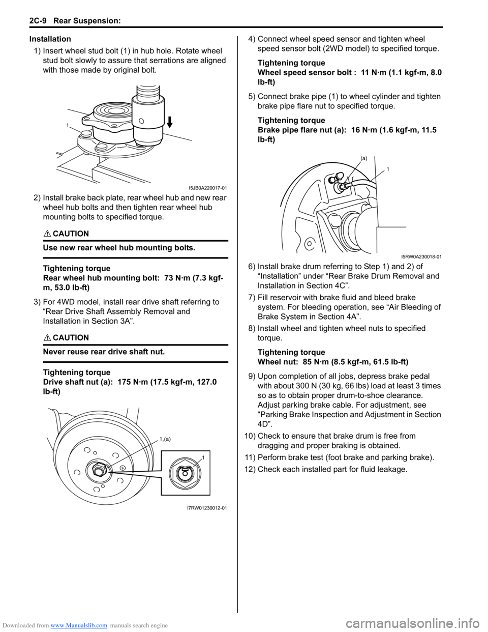
Installation
1) Insert wheel stud bolt (1) in hub hole. Rotate wheel
stud bolt slowly to assure that serrations are aligned
with those made by original bolt.
2) Install brake back plate, rear wheel hub and new rear
wheel hub bolts and then tighten rear wheel hub
mounting bolts to specified torque.
CAUTION!
Use new rear wheel hub mounting bolts.
Tightening torque
Rear wheel hub mounting bolt: 73 N·m (7.3 kgf-
m, 53.0 lb-ft)
3) For 4WD model, install rear drive shaft referring to
“Rear Drive Shaft Assembly Removal and
Installation in Section 3A”.
CAUTION!
Never reuse rear drive shaft nut.
Tightening torque
Drive shaft nut (a): 175 N·m (17.5 kgf-m, 127.0
lb-ft)4) Connect wheel speed sensor and tighten wheel
speed sensor bolt (2WD model) to specified torque.
Tightening torque
Wheel speed sensor bolt : 11 N·m (1.1 kgf-m, 8.0
lb-ft)
5) Connect brake pipe (1) to wheel cylinder and tighten
brake pipe flare nut to specified torque.
Tightening torque
Brake pipe flare nut (a): 16 N·m (1.6 kgf-m, 11.5
lb-ft)
6) Install brake drum referring to Step 1) and 2) of
“Installation” under “Rear Brake Drum Removal and
Installation in Section 4C”.
7) Fill reservoir with brake fluid and bleed brake
system. For bleeding operation, see “Air Bleeding of
Brake System in Section 4A”.
8) Install wheel and tighten wheel nuts to specified
torque.
Tightening torque
Wheel nut: 85 N·m (8.5 kgf-m, 61.5 lb-ft)
9) Upon completion of all jobs, depress brake pedal
with about 300 N (30 kg, 66 lbs) load at least 3 times
so as to obtain proper drum-to-shoe clearance.
Adjust parking brake cable. For adjustment, see
“Parking Brake Inspection and Adjustment in Section
4D”.
10) Check to ensure that brake drum is free from
dragging and proper braking is obtained.
11) Perform brake test (foot brake and parking brake).
12) Check each installed part for fluid leakage.
1
I5JB0A220017-01
1,(a)
1
I7RW01230012-01
(a)
1
I5RW0A230018-01
Page 471 of 1556
Downloaded from www.Manualslib.com manuals search engine Wheels and Tires: 2D-2
Replacement Tires
When replacement is necessary, the original equipment
type tire should be used. Refer to the Tire Placard.
Replacement tires should be of the same size, load
range and construction as those originally on the vehicle.
Use of any other size or type tire may affect ride,
handling, speedometer / odometer calibration, vehicle
ground clearance and tire or snow chain clearance to the
body and chassis.
It is recommended that new tires be installed in pairs on
the same axle. If necessary to replace only one tire, it
should be paired with the tire having the most tread, to
equalize braking traction.
WARNING!
Do not mix different types of tires on the
same vehicle such as radial, bias and bias-
belted tires except in emergencies, because
handling may be seriously affected and may
result in loss of control.
The metric term for tire inflation pressure is the kilo
pascal (kPa). Tire pressures is usually printed in both
kPa and kgf/cm
2 on the “Tire Placard”.
Metric tire gauges are available from tool suppliers.
The chart, shown in the table, converts commonly used
inflation pressures from kPa to kgf/cm
2 and psi.
Wheels DescriptionS6RW0D2401002
Wheel Maintenance
Wheel repairs that use welding, heating, or peening are
not approved. All damaged wheels should be replaced.
Replacement Wheels
Wheels must be replaced if they are bent, dented, have
excessive lateral or radial runout, air leak through welds,
have elongated bolt holes, if lug wheel bolts won’t stay
tight, or if they are heavily rusted. Wheels with greater
runout than shown in the following may cause
objectional vibrations.
Replacement wheels must be equivalent to the original
equipment wheels in load capacity, diameter, rim with
offset and mounting configuration. A wheel of improper
size or type may affect wheel and bearing life, brake
cooling, speedometer / odometer calibration, vehicle
ground clearance and tire clearance to body and
chassis.How to Measure Wheel Runout
To measure the wheel runout, it is necessary to use an
accurate dial indicator. The tire may be on or off the
wheel. The wheel should be installed to the wheel
balancer of the like for proper measurement.
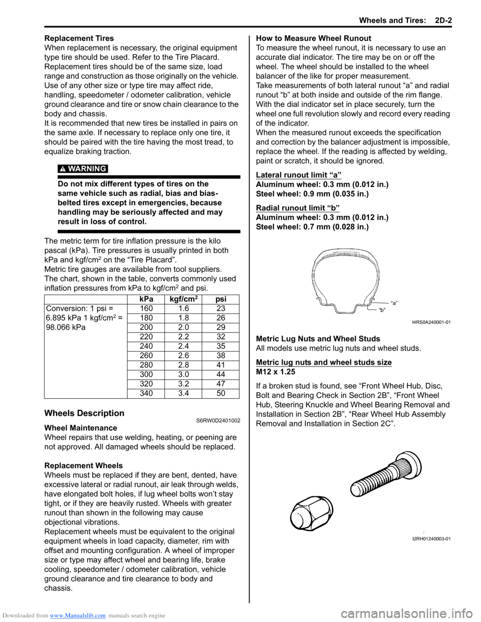
Take measurements of both lateral runout “a” and radial
runout “b” at both inside and outside of the rim flange.
With the dial indicator set in place securely, turn the
wheel one full revolution slowly and record every reading
of the indicator.
When the measured runout exceeds the specification
and correction by the balancer adjustment is impossible,
replace the wheel. If the reading is affected by welding,
paint or scratch, it should be ignored.
Lateral runout limit “a”
Aluminum wheel: 0.3 mm (0.012 in.)
Steel wheel: 0.9 mm (0.035 in.)
Radial runout limit “b”
Aluminum wheel: 0.3 mm (0.012 in.)
Steel wheel: 0.7 mm (0.028 in.)
Metric Lug Nuts and Wheel Studs
All models use metric lug nuts and wheel studs.
Metric lug nuts and wheel studs size
M12 x 1.25
If a broken stud is found, see “Front Wheel Hub, Disc,
Bolt and Bearing Check in Section 2B”, “Front Wheel
Hub, Steering Knuckle and Wheel Bearing Removal and
Installation in Section 2B”, “Rear Wheel Hub Assembly
Removal and Installation in Section 2C”. kPa kgf/cm
2psi
Conversion: 1 psi =
6.895 kPa 1 kgf/cm
2 =
98.066 kPa160 1.6 23
180 1.8 26
200 2.0 29
220 2.2 32
240 2.4 35
260 2.6 38
280 2.8 41
300 3.0 44
320 3.2 47
340 3.4 50I4RS0A240001-01
I2RH01240003-01
Page 474 of 1556
Downloaded from www.Manualslib.com manuals search engine 2D-5 Wheels and Tires:
Repair Instructions
Wheel Discs InspectionS6RW0D2406006
Inspect each wheel disc for dents, distortion and cracks.
A disc in badly damaged condition must be replaced.
Wheel Balance Inspection and AdjustmentS6RW0D2406001
Refer to “Balancing Wheels Description”.
Deposits of mud, etc. must be cleaned from inside of rim.
WARNING!
Stones should be removed from the tread in
order to avoid operator injury during spin
balancing and to obtain good balance.
Each tire should be inspected for any damage, then
balanced according to equipment manufacturer’s
recommendation.
Off-Vehicle Balancing
Most electronic off-vehicle balancers are more accurate
than the on-vehicle spin balancers. They are easy to use
and give a dynamic (two plane) balance. Although they
do not correct for drum or disc unbalance as does on-
vehicle spin balancing, this is overcome by their
accuracy, usually to within 1/8 ounce.
On-Vehicle Balancing
On-vehicle balancing methods vary with equipment and
tool manufacturers. Be sure to follow each
manufacturer’s instructions during balancing operation.
WARNING!
Wheel spin should be limited to 55 km/h (35
mph) as indicated on speedometer.
This limit is necessary because speedometer
only indicates one-half of actual wheel speed
when one drive wheel is spinning and the
other drive wheel is stopped.
Unless care is taken in limiting drive wheel
spin, spinning wheel can reach excessive
speeds. This can result in possible tire
disintegration or differential failure, which
could cause serious personal injury or
extensive vehicle damage.
CAUTION!
For vehicle equipped with ABS, using on-
vehicle balancing method with ignition
switch ON may set malfunction diagnostic
trouble code (DTC) of ABS even when system
is in good condition.
Never turn ignition switch ON while spinning
wheel.
Tire RotationS6RW0D2406002
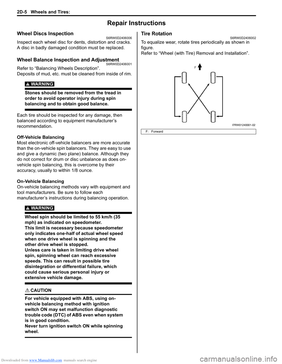
To equalize wear, rotate tires periodically as shown in
figure.
Refer to “Wheel (with Tire) Removal and Installation”.
F: Forward
I7RW01240001-02
Page 475 of 1556
Downloaded from www.Manualslib.com manuals search engine Wheels and Tires: 2D-6
Wheel (with Tire) Removal and InstallationS6RW0D2406003
Removal
CAUTION!
Never use heat to loosen tight wheel because
the application of heat to wheel causes the
wheel life shorter and the wheel bearing
damage.
1) Loosen wheel nuts by approximately 180° (half a
rotation).
2) Hoist vehicle.
3) Make sure that the vehicle will not fall off by trying to
move vehicle body in both ways.
4) Remove wheel nuts except one.
5) Support the wheel and/or tire not to drop the wheel
and then remove the nut left with the wheel.
Installation
For installation, reverse removal procedure, noting the
following.
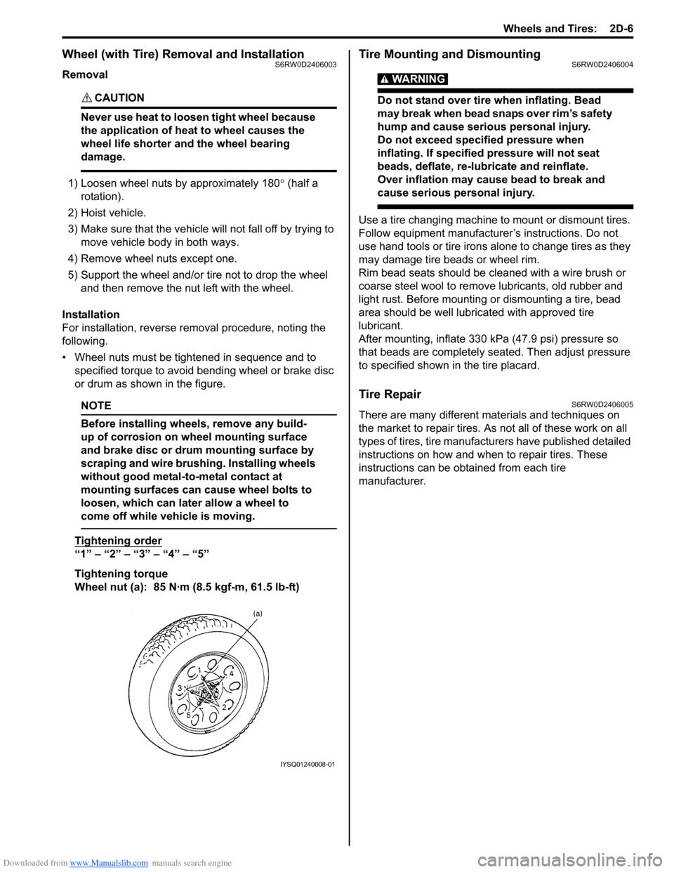
• Wheel nuts must be tightened in sequence and to
specified torque to avoid bending wheel or brake disc
or drum as shown in the figure.
NOTE
Before installing wheels, remove any build-
up of corrosion on wheel mounting surface
and brake disc or drum mounting surface by
scraping and wire brushing. Installing wheels
without good metal-to-metal contact at
mounting surfaces can cause wheel bolts to
loosen, which can later allow a wheel to
come off while vehicle is moving.
Tightening order
“1” – “2” – “3” – “4” – “5”
Tightening torque
Wheel nut (a): 85 N·m (8.5 kgf-m, 61.5 lb-ft)
Tire Mounting and DismountingS6RW0D2406004
WARNING!
Do not stand over tire when inflating. Bead
may break when bead snaps over rim’s safety
hump and cause serious personal injury.
Do not exceed specified pressure when
inflating. If specified pressure will not seat
beads, deflate, re-lubricate and reinflate.
Over inflation may cause bead to break and
cause serious personal injury.
Use a tire changing machine to mount or dismount tires.
Follow equipment manufacturer’s instructions. Do not
use hand tools or tire irons alone to change tires as they
may damage tire beads or wheel rim.
Rim bead seats should be cleaned with a wire brush or
coarse steel wool to remove lubricants, old rubber and
light rust. Before mounting or dismounting a tire, bead
area should be well lubricated with approved tire
lubricant.
After mounting, inflate 330 kPa (47.9 psi) pressure so
that beads are completely seated. Then adjust pressure
to specified shown in the tire placard.
Tire RepairS6RW0D2406005
There are many different materials and techniques on
the market to repair tires. As not all of these work on all
types of tires, tire manufacturers have published detailed
instructions on how and when to repair tires. These
instructions can be obtained from each tire
manufacturer.
IYSQ01240008-01
Page 477 of 1556
Downloaded from www.Manualslib.com manuals search engine Table of Contents 3- i
3
Section 3
CONTENTS
Driveline / Axle
Precautions ................................................. 3-1
Precautions............................................................. 3-1
Precautions on Driveline / Axle ............................. 3-1
Drive Shaft / Axle ..................................... 3A-1
Front ......................................................................... 3A-1
General Description ............................................. 3A-1
Front Drive Shaft Construction ............................ 3A-1
Component Location ........................................... 3A-1
Front Drive Shaft Assembly Components
Location ............................................................ 3A-1
Diagnostic Information and Procedures ............ 3A-2
Front Drive Shaft Symptom Diagnosis ................ 3A-2
Repair Instructions .............................................. 3A-2
Front Drive Shaft Components ........................... 3A-2
Front Drive Shaft Assembly On-Vehicle
Inspection.......................................................... 3A-3
Front Drive Shaft Assembly Removal and
Installation ......................................................... 3A-3
Front Drive Shaft Disassembly and
Reassembly ...................................................... 3A-4
Center Shaft and Center Bearing Support
Disassembly and Reassembly (If Equipped) .. 3A-12
Specifications..................................................... 3A-13
Tightening Torque Specifications ...................... 3A-13
Special Tools and Equipment ........................... 3A-14
Recommended Service Material ....................... 3A-14
Special Tool ...................................................... 3A-14
Rear ........................................................................ 3A-15
General Description ........................................... 3A-15
Rear Drive Shaft Construction .......................... 3A-15
Repair Instructions ............................................ 3A-15
Rear Drive Shaft Components .......................... 3A-15
Rear Drive Shaft Assembly Removal and
Installation ....................................................... 3A-16
Rear Drive Shaft Disassembly and
Reassembly .................................................... 3A-16
Specifications..................................................... 3A-18
Tightening Torque Specifications ...................... 3A-18
Special Tools and Equipment ........................... 3A-18
Recommended Service Material ....................... 3A-18
Special Tool ...................................................... 3A-18
Differential ................................................ 3B-1
Precautions...........................................................3B-1
Precaution for Rear Differential Oil Leakage....... 3B-1
Precautions in Diagnosing Trouble ..................... 3B-1
General Description .............................................3B-2
Rear Differential Description ............................... 3B-2
Coupling Description ........................................... 3B-2
4WD Control System Components ..................... 3B-3
4WD Control System Description........................ 3B-4
Function of 4WD Control System Component .... 3B-4
4WD Control System Wiring Circuit Diagram...... 3B-5
Terminal Arrangement of 4WD Control
Module .............................................................. 3B-5
Input / Output Signal Table of 4WD Control
Module .............................................................. 3B-6
On-Board Diagnostic System Description ........... 3B-6
CAN Communication System Description........... 3B-7
Diagnostic Information and Procedures ............3B-8
4WD Control System Check ............................... 3B-8
4WD Position Indicator Operation Check.......... 3B-10
4WD Control System Operation Inspection ...... 3B-10
Visual Inspection ............................................... 3B-11
DTC Check........................................................ 3B-11
DTC Clearance ................................................. 3B-11
DTC Table ......................................................... 3B-12
Fail-Safe Table .................................................. 3B-12
Scan Tool Data ................................................. 3B-13
Rear Differential Symptom Diagnosis ............... 3B-14
4WD Control Symptom Diagnosis..................... 3B-14
4WD Position Indicator Does Not Come ON at
Ignition Switch ON but Engine Stops .............. 3B-15
4WD Position Indicator Remains ON Steady
at Ignition Switch ON....................................... 3B-16
DTC C1240: 4WD Control Module Power
Supply Circuit Malfunction............................... 3B-17
DTC C1243: Internal Circuit Malfunction of
4WD Control Module ....................................... 3B-18
DTC C1250: Coupling Air Temperature
Sensor Circuit Open ........................................ 3B-19
DTC C1251: Coupling Air Temperature
Sensor Circuit Short ........................................ 3B-21
DTC C1252: Coupling Assembly Circuit Open .. 3B-22
DTC C1253: Coupling Assembly Circuit Short .. 3B-24
DTC C1254: 2WD/4WD Switch Malfunction ..... 3B-25
DTC U0073: Control Module Communication
Bus Off ............................................................ 3B-27
Page 478 of 1556
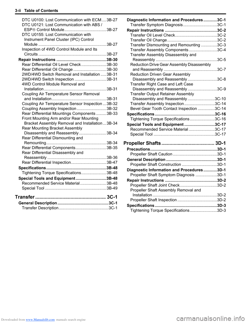
Downloaded from www.Manualslib.com manuals search engine 3-ii Table of Contents
DTC U0100: Lost Communication with ECM .... 3B-27
DTC U0121: Lost Communication with ABS /
ESP® Control Module..................................... 3B-27
DTC U0155: Lost Communication with
Instrument Panel Cluster (IPC) Control
Module ............................................................ 3B-27
Inspection of 4WD Control Module and Its
Circuits ............................................................ 3B-27
Repair Instructions ............................................3B-30
Rear Differential Oil Level Check ...................... 3B-30
Rear Differential Oil Change ............................. 3B-30
2WD/4WD Switch Removal and Installation ..... 3B-31
2WD/4WD Switch Inspection ............................ 3B-31
4WD Control Module Removal and
Installation ....................................................... 3B-31
Coupling Air Temperature Sensor Removal
and Installation ................................................ 3B-31
Coupling Air Temperature Sensor Inspection ... 3B-32
Coupling Assembly Inspection .......................... 3B-32
Rear Differential Mountings Components ......... 3B-33
Front Mounting Arm and/or Rear Mounting
Bracket Assembly Removal and Installation ... 3B-34
Rear Mounting Bracket Assembly
Disassembly and Reassembly ........................ 3B-34
Rear Differential Dismounting and
Remounting ..................................................... 3B-34
Rear Differential Components ........................... 3B-35
Rear Differential Disassembly and
Reassembly .................................................... 3B-36
Rear Differential Inspection ............................... 3B-47
Specifications .....................................................3B-48
Tightening Torque Specifications ...................... 3B-48
Special Tools and Equipment ...........................3B-48
Recommended Service Material ....................... 3B-48
Special Tool ...................................................... 3B-49
Transfer .................................................... 3C-1
General Description ............................................. 3C-1
Transfer Description ............................................ 3C-1Diagnostic Information and Procedures ............3C-1
Transfer Symptom Diagnosis..............................3C-1
Repair Instructions ..............................................3C-2
Transfer Oil Level Check.....................................3C-2
Transfer Oil Change ............................................3C-2
Transfer Dismounting and Remounting ..............3C-3
Transfer Assembly Components .........................3C-4
Transfer Assembly Disassembly and
Reassembly ......................................................3C-5
Reduction Drive Gear Assembly Disassembly
and Reassembly ...............................................3C-7
Reduction Driven Gear Assembly
Disassembly and Reassembly ..........................3C-8
Transfer Right Case and Left Case
Disassembly and Reassembly ..........................3C-9
Transfer Output Retainer Assembly
Disassembly and Reassembly ........................3C-10
Transfer Assembly Inspection ...........................3C-14
Bevel Gear Tooth Contact Inspection ...............3C-14
Specifications .....................................................3C-16
Tightening Torque Specifications ......................3C-16
Special Tools and Equipment ...........................3C-17
Recommended Service Material .......................3C-17
Special Tool ......................................................3C-17
Propeller Shafts ....................................... 3D-1
Precautions ...........................................................3D-1
Propeller Shaft Caution .......................................3D-1
General Description .............................................3D-1
Propeller Shaft Construction ...............................3D-1
Diagnostic Information and Procedures ............3D-1
Propeller Shaft Symptom Diagnosis ...................3D-1
Repair Instructions ..............................................3D-2
Propeller Shaft Joint Check.................................3D-2
Propeller Shaft Assembly Removal and
Installation .........................................................3D-2
Propeller Shaft Inspection ...................................3D-2
Specifications .......................................................3D-3
Tightening Torque Specifications ........................3D-3
Page 481 of 1556
Downloaded from www.Manualslib.com manuals search engine Drive Shaft / Axle: Front 3A-2
Diagnostic Information and Procedures
Front Drive Shaft Symptom DiagnosisS6RW0D3114001
Repair Instructions
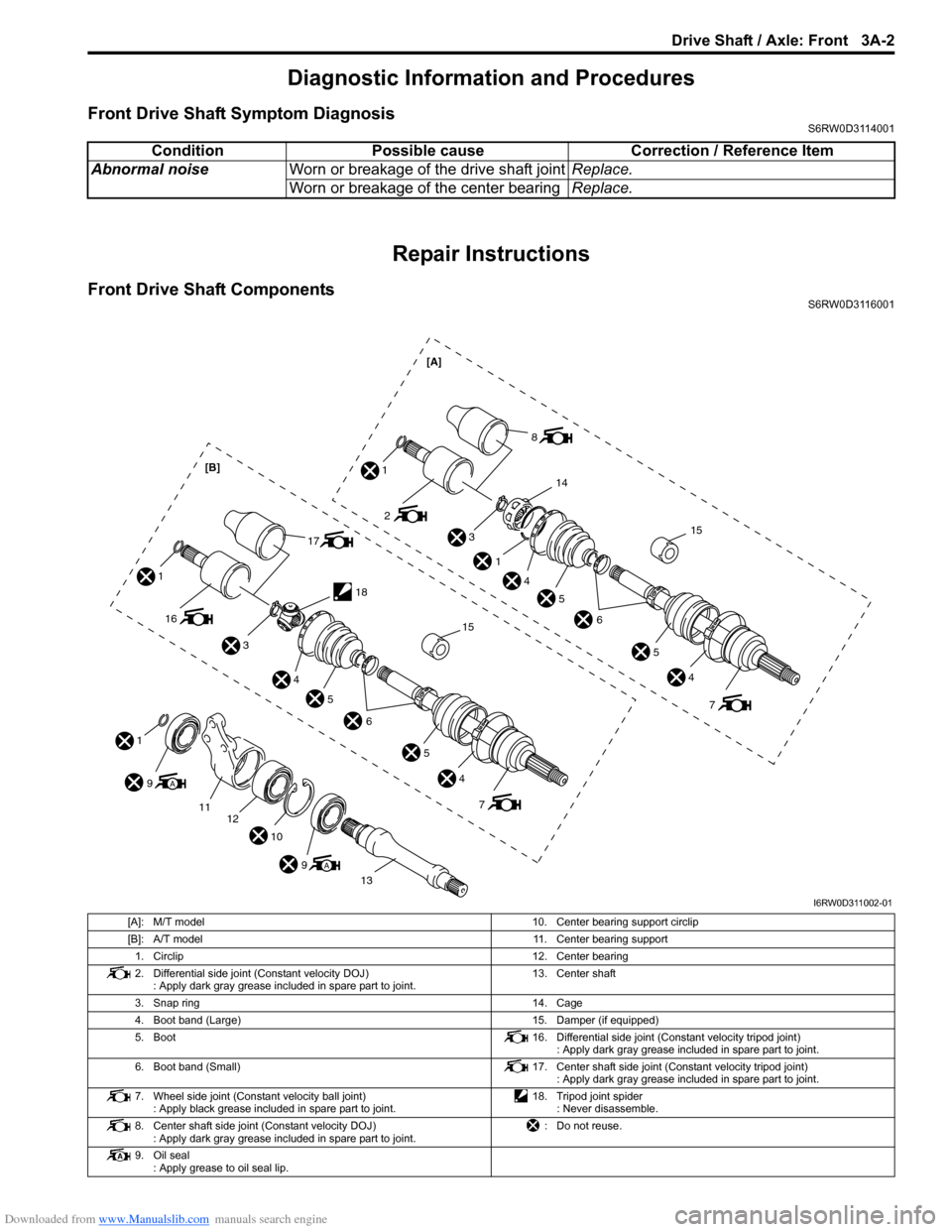
Front Drive Shaft ComponentsS6RW0D3116001
Condition Possible cause Correction / Reference Item
Abnormal noiseWorn or breakage of the drive shaft jointReplace.
Worn or breakage of the center bearingReplace.
1
9A
1112
10
9A
13
3
2
1
1
14
4
5
6
5
4
7
8
15
[A]
3
4
5
6
5
4
7
16
1
17
18
15
[B]
I6RW0D311002-01
[A]: M/T model 10. Center bearing support circlip
[B]: A/T model 11. Center bearing support
1. Circlip12. Center bearing
2. Differential side joint (Constant velocity DOJ)
: Apply dark gray grease included in spare part to joint.13. Center shaft
3. Snap ring 14. Cage
4. Boot band (Large) 15. Damper (if equipped)
5. Boot 16. Differential side joint (Constant velocity tripod joint)
: Apply dark gray grease included in spare part to joint.
6. Boot band (Small) 17. Center shaft side joint (Constant velocity tripod joint)
: Apply dark gray grease included in spare part to joint.
7. Wheel side joint (Constant velocity ball joint)
: Apply black grease included in spare part to joint.18. Tripod joint spider
: Never disassemble.
8. Center shaft side joint (Constant velocity DOJ)
: Apply dark gray grease included in spare part to joint.: Do not reuse.
9. Oil seal
: Apply grease to oil seal lip.