Rear View SUZUKI SX4 2006 1.G Service User Guide
[x] Cancel search | Manufacturer: SUZUKI, Model Year: 2006, Model line: SX4, Model: SUZUKI SX4 2006 1.GPages: 1556, PDF Size: 37.31 MB
Page 1324 of 1556

Downloaded from www.Manualslib.com manuals search engine 9B-5 Lighting Systems:
Schematic and Routing Diagram
Headlight Auto Leveling System Wiring Circuit DiagramS6RW0D9202001
G14-12G14-19G14-21
G14-10
G14-23
+B
5V
5V
GRN/YEL
GRY/RED
BLK
G14-112V
BRNLT BLUGRY
RED/BLK
3
G14-13G14-20G14-22
5V
PNKBLUYEL/GRN2
45
9
10 11 1
5V
5V
12V
G14-16
G14-3
PPL
GRN/ORN
5V
G14-5YEL
G14-17GRN
G14-11
G14-24
ORN
WHT6 12VG14-18LT GRN
7
8
G14-6
G14-9
RED/WHT
G14
10 11 12 13 16 17 18 19 205 6 9
21 22 23 24
[A]
I6RW0C920007-01
[A]: Headlight leveling control module connector
(viewed from harness side)4. BCM 8. Headlight leveling warning light
1. Headlight leveling control module 5. Right headlight leveling actuator 9. Ignition switch
2. Front height sensor 6. Left headlight leveling actuator 10. Lighting switch
3. Rear height sensor 7. Combination meter 11. Diagnosis connector
Page 1326 of 1556
Downloaded from www.Manualslib.com manuals search engine 9B-7 Lighting Systems:
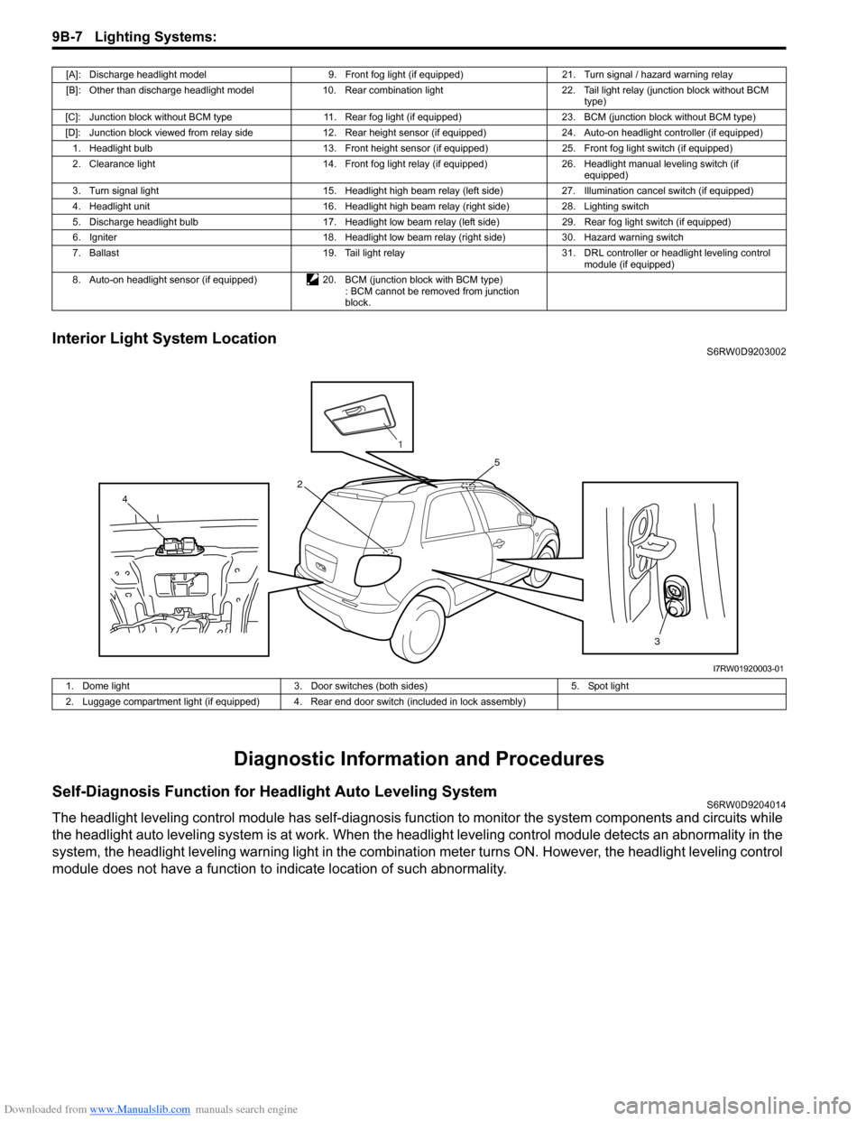
Interior Light System LocationS6RW0D9203002
Diagnostic Information and Procedures
Self-Diagnosis Function for Headlight Auto Leveling SystemS6RW0D9204014
The headlight leveling control module has self-diagnosis function to monitor the system components and circuits while
the headlight auto leveling system is at work. When the headlight leveling control module detects an abnormality in the
system, the headlight leveling warning light in the combination meter turns ON. However, the headlight leveling control
module does not have a function to indicate location of such abnormality.
[A]: Discharge headlight model 9. Front fog light (if equipped) 21. Turn signal / hazard warning relay
[B]: Other than discharge headlight model 10. Rear combination light 22. Tail light relay (junction block without BCM
type)
[C]: Junction block without BCM type 11. Rear fog light (if equipped) 23. BCM (junction block without BCM type)
[D]: Junction block viewed from relay side 12. Rear height sensor (if equipped) 24. Auto-on headlight controller (if equipped)
1. Headlight bulb 13. Front height sensor (if equipped) 25. Front fog light switch (if equipped)
2. Clearance light 14. Front fog light relay (if equipped) 26. Headlight manual leveling switch (if
equipped)
3. Turn signal light 15. Headlight high beam relay (left side) 27. Illumination cancel switch (if equipped)
4. Headlight unit 16. Headlight high beam relay (right side) 28. Lighting switch
5. Discharge headlight bulb 17. Headlight low beam relay (left side) 29. Rear fog light switch (if equipped)
6. Igniter 18. Headlight low beam relay (right side) 30. Hazard warning switch
7. Ballast 19. Tail light relay 31. DRL controller or headlight leveling control
module (if equipped)
8. Auto-on headlight sensor (if equipped) 20. BCM (junction block with BCM type)
: BCM cannot be removed from junction
block.
3 4
5
2
1
I7RW01920003-01
1. Dome light 3. Door switches (both sides) 5. Spot light
2. Luggage compartment light (if equipped) 4. Rear end door switch (included in lock assembly)
Page 1357 of 1556
Downloaded from www.Manualslib.com manuals search engine Instrumentation / Driver Info. / Horn: 9C-5
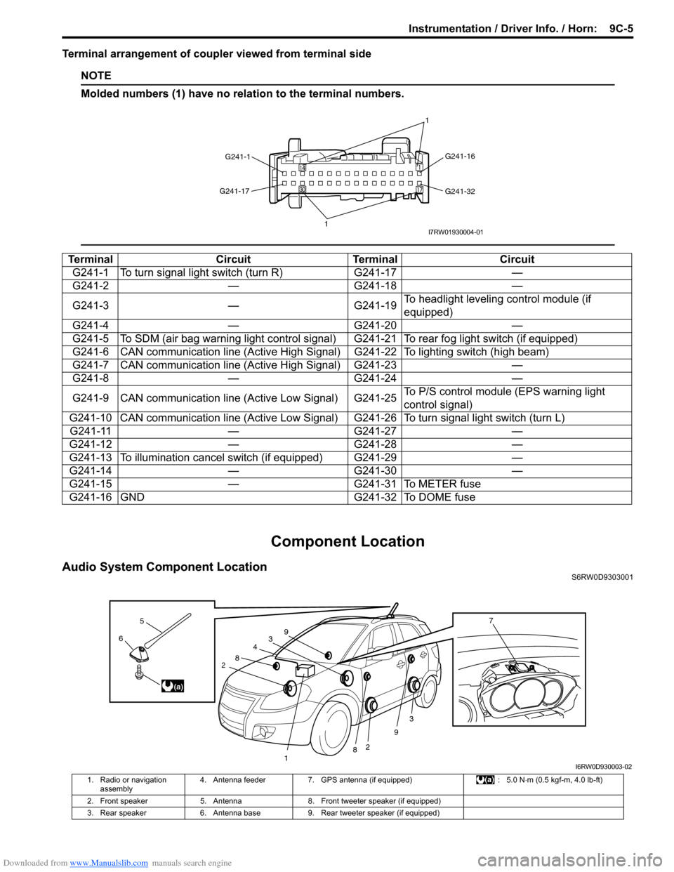
Terminal arrangement of coupler viewed from terminal side
NOTE
Molded numbers (1) have no relation to the terminal numbers.
Component Location
Audio System Component LocationS6RW0D9303001
Terminal Circuit Terminal Circuit
G241-1 To turn signal light switch (turn R) G241-17 —
G241-2 — G241-18 —
G241-3 — G241-19To headlight leveling control module (if
equipped)
G241-4 — G241-20 —
G241-5 To SDM (air bag warning light control signal) G241-21 To rear fog light switch (if equipped)
G241-6 CAN communication line (Active High Signal) G241-22 To lighting switch (high beam)
G241-7 CAN communication line (Active High Signal) G241-23 —
G241-8 — G241-24 —
G241-9 CAN communication line (Active Low Signal) G241-25To P/S control module (EPS warning light
control signal)
G241-10 CAN communication line (Active Low Signal) G241-26 To turn signal light switch (turn L)
G241-11 — G241-27 —
G241-12 — G241-28 —
G241-13 To illumination cancel switch (if equipped) G241-29 —
G241-14 — G241-30 —
G241-15 — G241-31 To METER fuse
G241-16 GND G241-32 To DOME fuse
G241-1G241-16
G241-32 G241-17
11I7RW01930004-01
3
2
3
2
1
4
8
8
9
96
5
(a)
7
I6RW0D930003-02
1. Radio or navigation
assembly4. Antenna feeder 7. GPS antenna (if equipped) : 5.0 Nâ‹…m (0.5 kgf-m, 4.0 lb-ft)
2. Front speaker 5. Antenna 8. Front tweeter speaker (if equipped)
3. Rear speaker 6. Antenna base 9. Rear tweeter speaker (if equipped)
Page 1376 of 1556
![SUZUKI SX4 2006 1.G Service User Guide Downloaded from www.Manualslib.com manuals search engine 9D-2 Wipers / Washers:
Repair Instructions
Wipers and Washers ComponentsS6RW0D9406001
115
6
(b)
(a) 1 1
(b)
2
1314
14[A]
14
1215
(c)
(b)
(a)
3 SUZUKI SX4 2006 1.G Service User Guide Downloaded from www.Manualslib.com manuals search engine 9D-2 Wipers / Washers:
Repair Instructions
Wipers and Washers ComponentsS6RW0D9406001
115
6
(b)
(a) 1 1
(b)
2
1314
14[A]
14
1215
(c)
(b)
(a)
3](/img/20/7612/w960_7612-1375.png)
Downloaded from www.Manualslib.com manuals search engine 9D-2 Wipers / Washers:
Repair Instructions
Wipers and Washers ComponentsS6RW0D9406001
115
6
(b)
(a) 1 1
(b)
2
1314
14[A]
14
1215
(c)
(b)
(a)
32
4
710
10
10 11118
16
9
16
I7RW01940001-03
1. Windshield wiper blade 8. Washer pump for rear washer 15. Windshield wiper bolt
:Tighten bolts in specified order.
2. Windshield wiper arm 9. Washer tank 16. Washer tank bolt
3. Windshield wiper motor 10. Washer hose[A]: Junction block viewed from relay
side
4. Windshield wiper link 11. Washer nozzle : 18 Nâ‹…m (1.8 kgf-m, 13.0 lb-ft)
Page 1387 of 1556
Downloaded from www.Manualslib.com manuals search engine Glass / Windows / Mirrors: 9E-2
Schematic and Routing Diagram
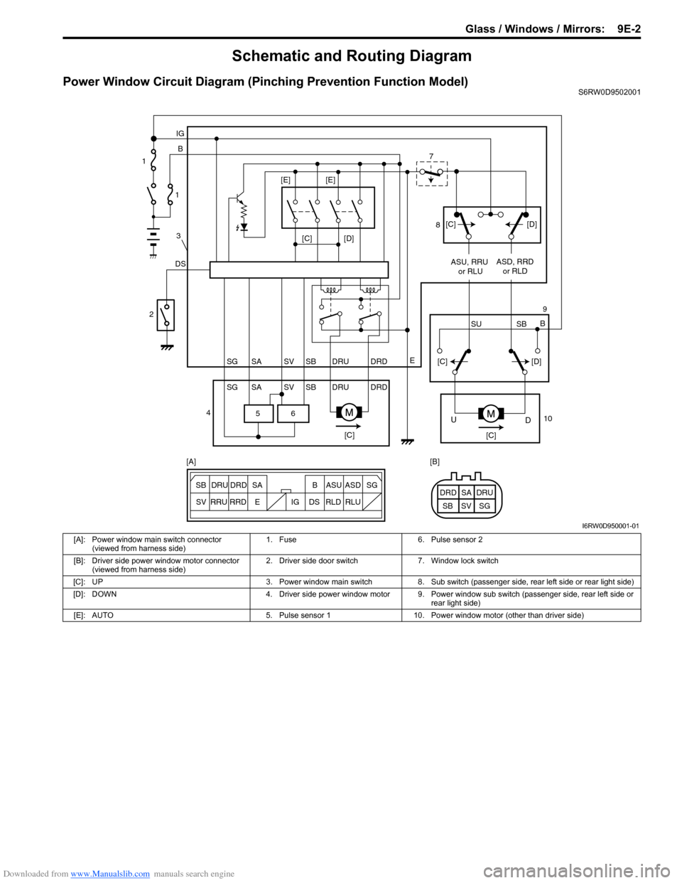
Power Window Circuit Diagram (Pinching Prevention Function Model)S6RW0D9502001
6 5
[C][D]
DSB IG
E
SG SV SBSA DRU DRD
SG SV SBSA DRU DRDASU, RRU
or RLUASD, RRD
or RLD
[C][C]
D U
[C][D]
SU SBB [C][D] [E] [E]
ESG
SV SB SADRU DRD B ASU ASD
RRU
RRDDS IG RLD RLUSG SV SBSA DRU DRD [A] [B] 1
1
3
2
47
8
9
10
I6RW0D950001-01
[A]: Power window main switch connector
(viewed from harness side)1. Fuse 6. Pulse sensor 2
[B]: Driver side power window motor connector
(viewed from harness side)2. Driver side door switch 7. Window lock switch
[C]: UP 3. Power window main switch 8. Sub switch (passenger side, rear left side or rear light side)
[D]: DOWN 4. Driver side power window motor 9. Power window sub switch (passenger side, rear left side or
rear light side)
[E]: AUTO 5. Pulse sensor 1 10. Power window motor (other than driver side)
Page 1391 of 1556
Downloaded from www.Manualslib.com manuals search engine Glass / Windows / Mirrors: 9E-6
Windshield Removal and InstallationS6RW0D9506002
Preparation
The windshield is installed by using a special type of
adhesive (that is, one component urethane adhesive
used with primer). For the windshield replacement, it is
important to use an adhesive which provides sufficient
adhesion strength and follow the proper procedure.
CAUTION!
• Described is the glass replacement by
using 3 types of primers and 1 type of
adhesive made by YOKOHAMA (one
component urethane adhesive to be used
with primer in combination). When using
primer and adhesive made by other
manufacturers, be sure to refer to handling
instructions supplied with them.
Negligence in following such procedure or
misuse of the adhesive in any way hinders
its inherent adhesive property. Therefore,
before the work, make sure to read
carefully the instruction and description
given by the maker of the adhesive to be
used and be sure to follow the procedure
and observe each precaution throughout
the work.
• Should coated surface be scratched or
otherwise damaged, be sure to repair
damaged part, or corrosion may start from
there.
Use the specific adhesive which has the following
property.
Glass adhesive shearing strength
40 kg/cm2 (569 lb/in2) or moreAdhesive materials and tools required for removal and
installation.
• One component urethane adhesive and primers used
in combination (For one sheet of windshield).
– Adhesive (470 g (15.7 oz.))
– Primer for glass (30 g (1.0 oz.))
– Primer for body (30 g (1.0 oz.))
– Primer for molding (30 g (1.0 oz.))
• Eyeleteer
•Piano string
• Windshield knife
• Brush for primer application (2 pcs)
•Knife
• Rubber sucker grip
• Sealant gun (for filling adhesive)
• Putty spatula (for correcting adhered parts)
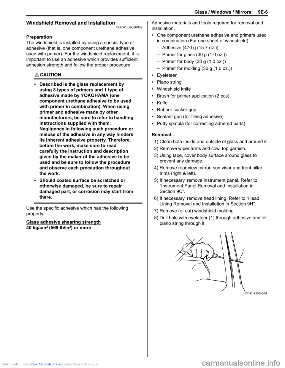
Removal
1) Clean both inside and outside of glass and around it.
2) Remove wiper arms and cowl top garnish.
3) Using tape, cover body surface around glass to
prevent any damage.
4) Remove rear view mirror, sun visor and front pillar
trims (right & left).
5) If necessary, remove instrument panel. Refer to
“Instrument Panel Removal and Installation in
Section 9C”.
6) If necessary, remove head lining. Refer to “Head
Lining Removal and Installation in Section 9H”.
7) Remove (or cut) windshield molding.
8) Drill hole with eyeleteer (1) through adhesive and let
piano string through it.
I2RH01950040-01
Page 1479 of 1556

Downloaded from www.Manualslib.com manuals search engine Body Electrical Control System: 10B-6
Connector Layout Diagram of BCM and Junction BlockS6RW0DA202002
BCM and Junction Block Connectors (Viewed from Harness Side)
I6RW0CA20004-01
[A]: Junction block (viewed from BCM side) 2. Junction block 5. Rear wiper relay
[B]: Junction block (viewed from relay side) 3. Blower motor relay 6. Rear end door window defogger relay
1. BCM 4. Horn relay 7. Turn signal and hazard warning relay
Page 1529 of 1556
Downloaded from www.Manualslib.com manuals search engine Keyless Start System: 10E-7
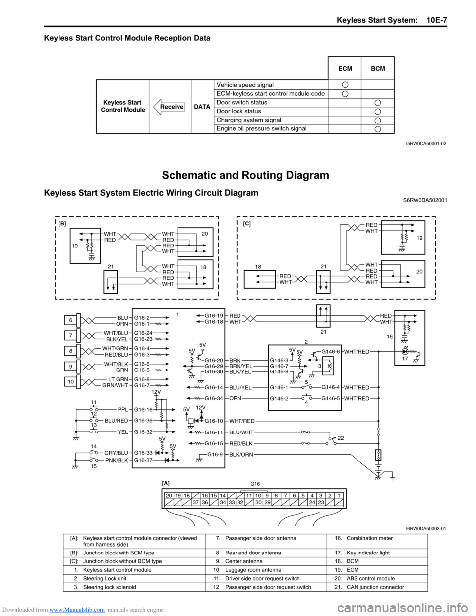
Keyless Start Control Module Reception Data
Schematic and Routing Diagram
Keyless Start System Electric Wiring Circuit DiagramS6RW0DA502001
Vehicle speed signal
ECM-keyless start control module code
Door switch status
Door lock status
Charging system signal
Engine oil pressure switch signalECM BCM
DATA
ReceiveKeyless Start
Control Module
I5RW0CA50001-02
BLK/ORNG16-9
G16-15
G16-14
G16-37G16-33
G16-16
G16-20G16-29G16-30
G16-36
G16-32
G16-10
G16-34
G16-11BLU/WHT
WHT/RED
WHT/RED
PNK/BLKGRY/BLU
BLU/RED
YEL
PPL
RED/BLK
5V5V 5V5V
5V5V
5V12V 12V
G16-2G16-1BLU
ORNWHTREDWHTREDG16-18G16-19
BLU/YEL
ORN
G16-24G16-23
BLK/YEL WHT/BLU
G16-7
GRN/WHTLT GRNG16-8
G16-5G16-6
GRN WHT/BLK
G16-4G16-3 WHT/GRN
RED/BLU
BLK/YELBRN/YELBRNG146-3
G146-1
G146-2G146-5
G146-4
G146-6
G146-7G146-8
WHT/RED
WHT/RED
G16[A]
1 2 3 4 5 6 7 8 9 10 11 14 15 16
36 34 33 32 30 29 24 23 37 18 19 20
WHTRED
WHT
WHT
RED
RED
WHTRED
6
7
8
9
10
11
12
13
14
15118
21
21
2
3
5
419
20
16
17
22
WHTRED
WHTREDWHTRED
18 1920WHTRED
WHTRED
21
[B][C]
I6RW0DA50002-01
[A]: Keyless start control module connector (viewed
from harness side)7. Passenger side door antenna 16. Combination meter
[B]: Junction block with BCM type 8. Rear end door antenna 17. Key indicator light
[C]: Junction block without BCM type 9. Center antenna 18. BCM
1. Keyless start control module 10. Luggage room antenna 19. ECM
2. Steering Lock unit 11. Driver side door request switch 20. ABS control module
3. Steering lock solenoid 12. Passenger side door request switch 21. CAN junction connector
Page 1537 of 1556
Downloaded from www.Manualslib.com manuals search engine Keyless Start System: 10E-15
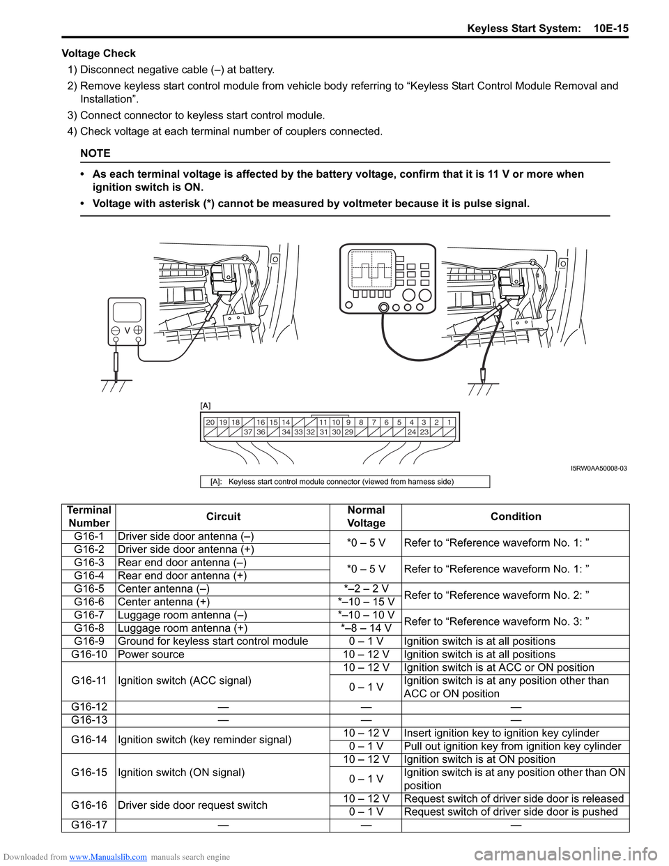
Voltage Check
1) Disconnect negative cable (–) at battery.
2) Remove keyless start control module from vehicle body referring to “Keyless Start Control Module Removal and
Installation”.
3) Connect connector to keyless start control module.
4) Check voltage at each terminal number of couplers connected.
NOTE
• As each terminal voltage is affected by the battery voltage, confirm that it is 11 V or more when
ignition switch is ON.
• Voltage with asterisk (*) cannot be measured by voltmeter because it is pulse signal.
1 2 3 4 5 6 7 8 9 10 11 14 15 16
36 34 33 32 31 30 29 24 23 37 18 19 20
[A]
I5RW0AA50008-03
[A]: Keyless start control module connector (viewed from harness side)
Terminal
NumberCircuitNormal
Vo l ta g eCondition
G16-1 Driver side door antenna (–)
*0 – 5 V Refer to “Reference waveform No. 1: ”
G16-2 Driver side door antenna (+)
G16-3 Rear end door antenna (–)
*0 – 5 V Refer to “Reference waveform No. 1: ”
G16-4 Rear end door antenna (+)
G16-5 Center antenna (–) *–2 – 2 V
Refer to “Reference waveform No. 2: ”
G16-6 Center antenna (+) *–10 – 15 V
G16-7 Luggage room antenna (–) *–10 – 10 V
Refer to “Reference waveform No. 3: ”
G16-8 Luggage room antenna (+) *–8 – 14 V
G16-9 Ground for keyless start control module 0 – 1 V Ignition switch is at all positions
G16-10 Power source 10 – 12 V Ignition switch is at all positions
G16-11 Ignition switch (ACC signal)10 – 12 V Ignition switch is at ACC or ON position
0 – 1 VIgnition switch is at any position other than
ACC or ON position
G16-12 — — —
G16-13 — — —
G16-14 Ignition switch (key reminder signal)10 – 12 V Insert ignition key to ignition key cylinder
0 – 1 V Pull out ignition key from ignition key cylinder
G16-15 Ignition switch (ON signal)10 – 12 V Ignition switch is at ON position
0 – 1 VIgnition switch is at any position other than ON
position
G16-16 Driver side door request switch10 – 12 V Request switch of driver side door is released
0 – 1 V Request switch of driver side door is pushed
G16-17 — — —
Page 1542 of 1556
Downloaded from www.Manualslib.com manuals search engine 10E-20 Keyless Start System:
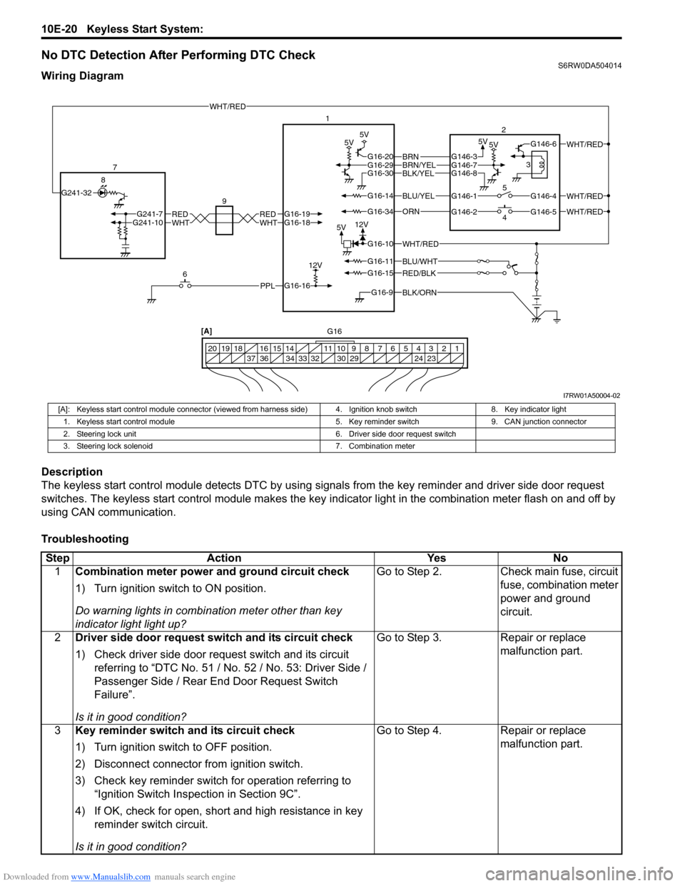
No DTC Detection After Performing DTC CheckS6RW0DA504014
Wiring Diagram
Description
The keyless start control module detects DTC by using signals from the key reminder and driver side door request
switches. The keyless start control module makes the key indicator light in the combination meter flash on and off by
using CAN communication.
Troubleshooting
BLK/ORNG16-9
G16-15
G16-14
G16-16
G16-20G16-29G16-30
G16-10
G16-34
G16-11BLU/WHT
WHT/RED
WHT/RED
WHT/RED
PPL
RED/BLK
5V5V 5V5V
5V12V
12VWHTREDWHTREDG16-18G16-19G241-10G241-7
BLU/YEL
ORN
BLK/YELBRN/YELBRNG146-3
G146-1
G146-2G146-5
G146-4
G146-6
G146-7G146-8
WHT/RED
WHT/RED
G241-32
6 7
81
2
4 53
20 12 3 4 5 6 7 8 9 10 11 14 15 16
36 34 33 32 30 29 24 23 37 18 19
[A]
9
G16
I7RW01A50004-02
[A]: Keyless start control module connector (viewed from harness side) 4. Ignition knob switch 8. Key indicator light
1. Keyless start control module 5. Key reminder switch 9. CAN junction connector
2. Steering lock unit 6. Driver side door request switch
3. Steering lock solenoid 7. Combination meter
Step Action Yes No
1Combination meter power and ground circuit check
1) Turn ignition switch to ON position.
Do warning lights in combination meter other than key
indicator light light up?Go to Step 2. Check main fuse, circuit
fuse, combination meter
power and ground
circuit.
2Driver side door request switch and its circuit check
1) Check driver side door request switch and its circuit
referring to “DTC No. 51 / No. 52 / No. 53: Driver Side /
Passenger Side / Rear End Door Request Switch
Failure”.
Is it in good condition?Go to Step 3. Repair or replace
malfunction part.
3Key reminder switch and its circuit check
1) Turn ignition switch to OFF position.
2) Disconnect connector from ignition switch.
3) Check key reminder switch for operation referring to
“Ignition Switch Inspection in Section 9C”.
4) If OK, check for open, short and high resistance in key
reminder switch circuit.
Is it in good condition?Go to Step 4. Repair or replace
malfunction part.