brake line SUZUKI SX4 2006 1.G Service User Guide
[x] Cancel search | Manufacturer: SUZUKI, Model Year: 2006, Model line: SX4, Model: SUZUKI SX4 2006 1.GPages: 1556, PDF Size: 37.31 MB
Page 97 of 1556
Downloaded from www.Manualslib.com manuals search engine Engine General Information and Diagnosis: 1A-47
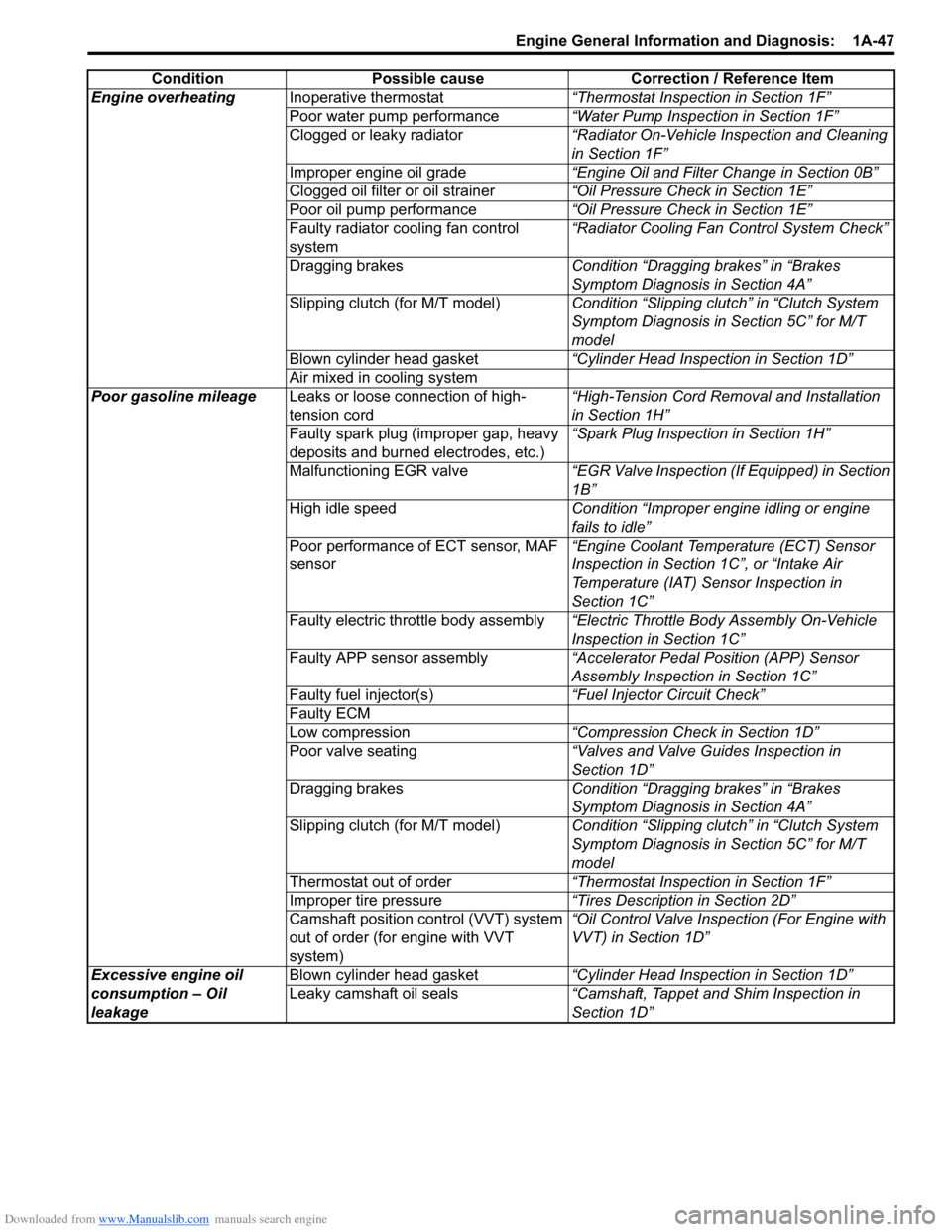
Engine overheatingInoperative thermostat“Thermostat Inspection in Section 1F”
Poor water pump performance“Water Pump Inspection in Section 1F”
Clogged or leaky radiator“Radiator On-Vehicle Inspection and Cleaning
in Section 1F”
Improper engine oil grade“Engine Oil and Filter Change in Section 0B”
Clogged oil filter or oil strainer“Oil Pressure Check in Section 1E”
Poor oil pump performance“Oil Pressure Check in Section 1E”
Faulty radiator cooling fan control
system“Radiator Cooling Fan Control System Check”
Dragging brakesCondition “Dragging brakes” in “Brakes
Symptom Diagnosis in Section 4A”
Slipping clutch (for M/T model)Condition “Slipping clutch” in “Clutch System
Symptom Diagnosis in Section 5C” for M/T
model
Blown cylinder head gasket“Cylinder Head Inspection in Section 1D”
Air mixed in cooling system
Poor gasoline mileageLeaks or loose connection of high-
tension cord“High-Tension Cord Removal and Installation
in Section 1H”
Faulty spark plug (improper gap, heavy
deposits and burned electrodes, etc.)“Spark Plug Inspection in Section 1H”
Malfunctioning EGR valve“EGR Valve Inspection (If Equipped) in Section
1B”
High idle speedCondition “Improper engine idling or engine
fails to idle”
Poor performance of ECT sensor, MAF
sensor“Engine Coolant Temperature (ECT) Sensor
Inspection in Section 1C”, or “Intake Air
Temperature (IAT) Sensor Inspection in
Section 1C”
Faulty electric throttle body assembly“Electric Throttle Body Assembly On-Vehicle
Inspection in Section 1C”
Faulty APP sensor assembly“Accelerator Pedal Position (APP) Sensor
Assembly Inspection in Section 1C”
Faulty fuel injector(s)“Fuel Injector Circuit Check”
Faulty ECM
Low compression“Compression Check in Section 1D”
Poor valve seating“Valves and Valve Guides Inspection in
Section 1D”
Dragging brakesCondition “Dragging brakes” in “Brakes
Symptom Diagnosis in Section 4A”
Slipping clutch (for M/T model)Condition “Slipping clutch” in “Clutch System
Symptom Diagnosis in Section 5C” for M/T
model
Thermostat out of order“Thermostat Inspection in Section 1F”
Improper tire pressure“Tires Description in Section 2D”
Camshaft position control (VVT) system
out of order (for engine with VVT
system)“Oil Control Valve Inspection (For Engine with
VVT) in Section 1D”
Excessive engine oil
consumption – Oil
leakageBlown cylinder head gasket“Cylinder Head Inspection in Section 1D”
Leaky camshaft oil seals“Camshaft, Tappet and Shim Inspection in
Section 1D” Condition Possible cause Correction / Reference Item
Page 99 of 1556
Downloaded from www.Manualslib.com manuals search engine Engine General Information and Diagnosis: 1A-49
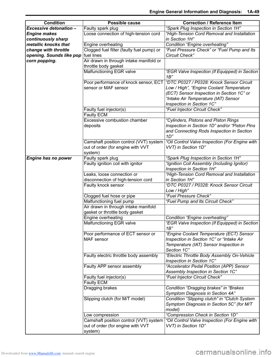
Excessive detonation –
Engine makes
continuously sharp
metallic knocks that
change with throttle
opening. Sounds like pop
corn popping.Faulty spark plug“Spark Plug Inspection in Section 1H”
Loose connection of high-tension cord“High-Tension Cord Removal and Installation
in Section 1H”
Engine overheatingCondition “Engine overheating”
Clogged fuel filter (faulty fuel pump) or
fuel lines“Fuel Pressure Check” or “Fuel Pump and Its
Circuit Check”
Air drawn in through intake manifold or
throttle body gasket
Malfunctioning EGR valve“EGR Valve Inspection (If Equipped) in Section
1B”
Poor performance of knock sensor, ECT
sensor or MAF sensor“DTC P0327 / P0328: Knock Sensor Circuit
Low / High”, “Engine Coolant Temperature
(ECT) Sensor Inspection in Section 1C” or
“Intake Air Temperature (IAT) Sensor
Inspection in Section 1C”
Faulty fuel injector(s)“Fuel Injector Circuit Check”
Faulty ECM
Excessive combustion chamber
deposits“Cylinders, Pistons and Piston Rings
Inspection in Section 1D” and/or “Piston Pins
and Connecting Rods Inspection in Section
1D”
Camshaft position control (VVT) system
out of order (for engine with VVT
system)“Oil Control Valve Inspection (For Engine with
VVT) in Section 1D”
Engine has no powerFaulty spark plug“Spark Plug Inspection in Section 1H”
Faulty ignition coil with ignitor“Ignition Coil Assembly (Including Ignitor)
Inspection in Section 1H”
Leaks, loose connection or
disconnection of high-tension cord“High-Tension Cord Removal and Installation
in Section 1H”
Faulty knock sensor“DTC P0327 / P0328: Knock Sensor Circuit
Low / High”
Clogged fuel hose or pipe“Fuel Pressure Check”
Malfunctioning fuel pump“Fuel Pump and Its Circuit Check”
Air drawn in through intake manifold
gasket or throttle body gasket
Engine overheatingCondition “Engine overheating”
Malfunctioning EGR valve“EGR Valve Inspection (If Equipped) in Section
1B”
Poor performance of ECT sensor or
MAF sensor“Engine Coolant Temperature (ECT) Sensor
Inspection in Section 1C” or “Intake Air
Temperature (IAT) Sensor Inspection in
Section 1C”
Faulty electric throttle body assembly“Electric Throttle Body Assembly On-Vehicle
Inspection in Section 1C”
Faulty APP sensor assembly“Accelerator Pedal Position (APP) Sensor
Assembly Inspection in Section 1C”
Faulty fuel injector(s)“Fuel Injector Circuit Check”
Faulty ECM
Dragging brakesCondition “Dragging brakes” in “Brakes
Symptom Diagnosis in Section 4A”
Slipping clutch (for M/T model)Condition “Slipping clutch” in “Clutch System
Symptom Diagnosis in Section 5C” (for M/T
model)
Low compression“Compression Check in Section 1D”
Camshaft position control (VVT) system
out of order (for engine with VVT
system)“Oil Control Valve Inspection (For Engine with
VVT) in Section 1D” Condition Possible cause Correction / Reference Item
Page 228 of 1556
Downloaded from www.Manualslib.com manuals search engine 1A-178 Engine General Information and Diagnosis:
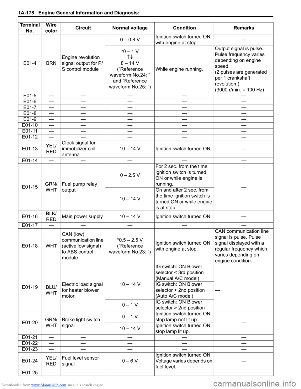
E01-4 BRNEngine revolution
signal output for P/
S control module0 – 0.8 VIgnition switch turned ON
with engine at stop.—
*0 – 1 V
↑↓
8 – 14 V
(“Reference
waveform No.24: ”
and “Reference
waveform No.25: ”)While engine running.Output signal is pulse.
Pulse frequency varies
depending on engine
speed.
(2 pulses are generated
per 1 crankshaft
revolution.)
(3000 r/min. = 100 Hz)
E01-5 — — — — —
E01-6 — — — — —
E01-7 — — — — —
E01-8 — — — — —
E01-9 — — — — —
E01-10 — — — — —
E01-11 — — — — —
E01-12 — — — — —
E01-13YEL/
REDClock signal for
immobilizer coil
antenna10 – 14 V Ignition switch turned ON. —
E01-14 — — — — —
E01-15GRN/
WHTFuel pump relay
output0 – 2.5 VFor 2 sec. from the time
ignition switch is turned
ON or while engine is
running.
—
10 – 14 VOn and after 2 sec. from
the time ignition switch is
turned ON or while engine
is at stop.
E01-16BLK/
REDMain power supply 10 – 14 V Ignition switch turned ON. —
E01-17 — — — — —
E01-18 WHTCAN (low)
communication line
(active low signal)
to ABS control
module*0.5 – 2.5 V
(“Reference
waveform No.23: ”)Ignition switch turned ON
with engine at stop.CAN communication line
signal is pulse. Pulse
signal displayed with a
regular frequency which
varies depending on
engine condition.
E01-19 BLU/
WHTElectric load signal
for heater blower
motor10 – 14 VIG switch: ON Blower
selector < 3rd position
(Manual A/C model)
— IG switch: ON Blower
selector < 2nd position
(Auto A/C model)
0 – 1 VIG switch: ON Blower
selector > 2nd position
E01-20GRN/
WHTBrake light switch
signal0 – 1 VIgnition switch turned ON,
stop lamp not lit up.
—
10 – 14 VIgnition switch turned ON,
stop lamp lit up.
E01-21 — — — — —
E01-22 — — — — —
E01-23 — — — — —
E01-24YEL/
REDFuel level sensor
signal0 – 6 VIgnition switch turned ON.
Voltage varies depends on
fuel level.—
E01-25 — — — — — Terminal
No.Wire
colorCircuit Normal voltage Condition Remarks
Page 288 of 1556
Downloaded from www.Manualslib.com manuals search engine 1D-6 Engine Mechanical:
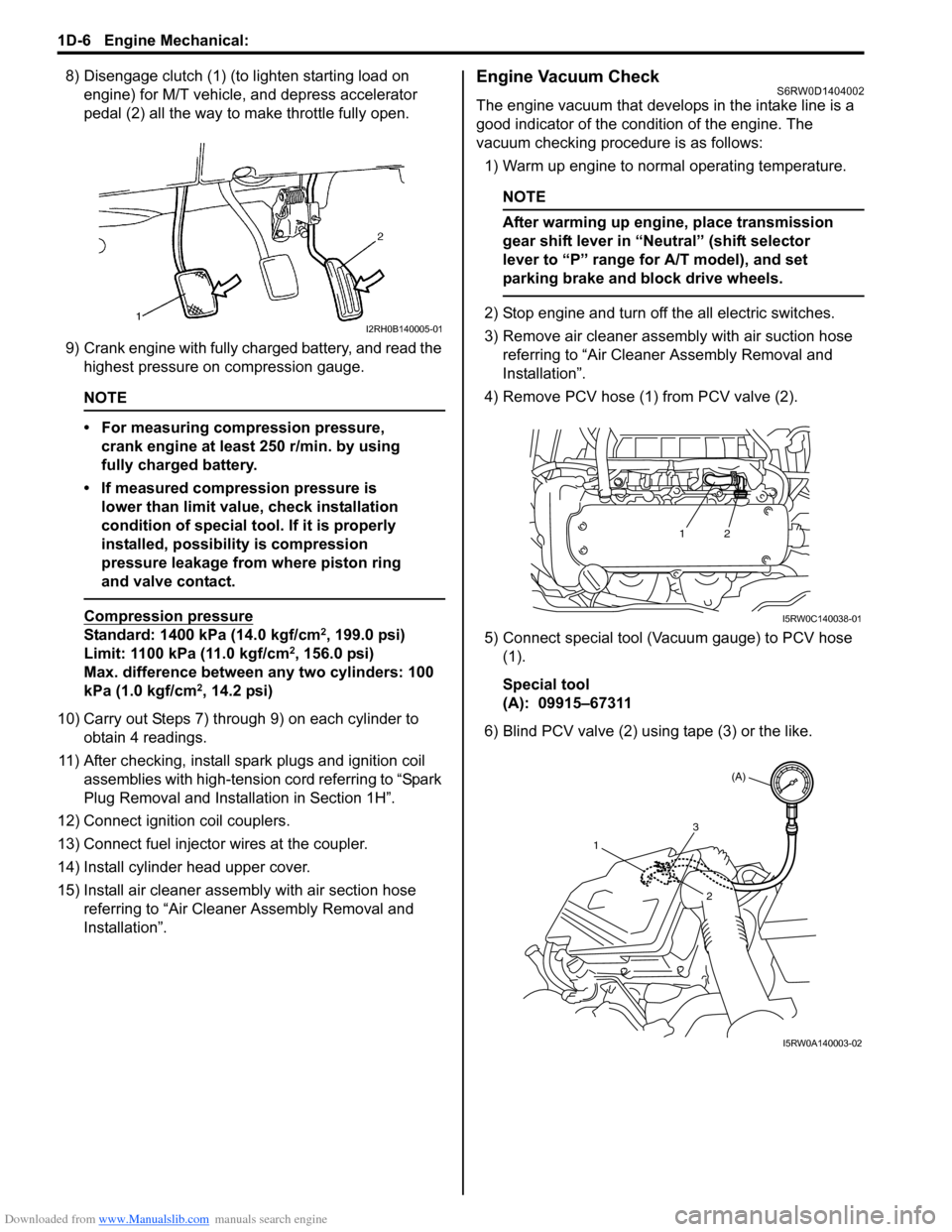
8) Disengage clutch (1) (to lighten starting load on
engine) for M/T vehicle, and depress accelerator
pedal (2) all the way to make throttle fully open.
9) Crank engine with fully charged battery, and read the
highest pressure on compression gauge.
NOTE
• For measuring compression pressure,
crank engine at least 250 r/min. by using
fully charged battery.
• If measured compression pressure is
lower than limit value, check installation
condition of special tool. If it is properly
installed, possibility is compression
pressure leakage from where piston ring
and valve contact.
Compression pressure
Standard: 1400 kPa (14.0 kgf/cm2, 199.0 psi)
Limit: 1100 kPa (11.0 kgf/cm2, 156.0 psi)
Max. difference between any two cylinders: 100
kPa (1.0 kgf/cm
2, 14.2 psi)
10) Carry out Steps 7) through 9) on each cylinder to
obtain 4 readings.
11) After checking, install spark plugs and ignition coil
assemblies with high-tension cord referring to “Spark
Plug Removal and Installation in Section 1H”.
12) Connect ignition coil couplers.
13) Connect fuel injector wires at the coupler.
14) Install cylinder head upper cover.
15) Install air cleaner assembly with air section hose
referring to “Air Cleaner Assembly Removal and
Installation”.
Engine Vacuum CheckS6RW0D1404002
The engine vacuum that develops in the intake line is a
good indicator of the condition of the engine. The
vacuum checking procedure is as follows:
1) Warm up engine to normal operating temperature.
NOTE
After warming up engine, place transmission
gear shift lever in “Neutral” (shift selector
lever to “P” range for A/T model), and set
parking brake and block drive wheels.
2) Stop engine and turn off the all electric switches.
3) Remove air cleaner assembly with air suction hose
referring to “Air Cleaner Assembly Removal and
Installation”.
4) Remove PCV hose (1) from PCV valve (2).
5) Connect special tool (Vacuum gauge) to PCV hose
(1).
Special tool
(A): 09915–67311
6) Blind PCV valve (2) using tape (3) or the like.I2RH0B140005-01
12
I5RW0C140038-01
(A)
1
2
3
I5RW0A140003-02
Page 381 of 1556
Downloaded from www.Manualslib.com manuals search engine Fuel System: 1G-4
4) Check that battery voltage is 11 V or more.
5) Measure fuel pressure at each condition.
If measured pressure is out of specification, refer to
“Fuel Pressure Check in Section 1A” and check each
possibly defective part. Replace if found defective.
a) Turn ignition switch ON to operate fuel pump and
after 2 seconds turn it OFF. Repeat this 3 or 4
times and then check fuel pressure.
Fuel pressure specification
With fuel pump operating and engine
stopped: 360 – 400 kPa (3.6 – 4.0 kgf/cm2,
51.2 – 56.9 psi)
b) Start engine and warm it up to normal operating
temperature, and measure fuel pressure at
idling.
Fuel pressure specification
At specified idle speed: 360 – 400 kPa (3.6 –
4.0 kgf/cm2, 51.2 – 56.9 psi)
c) Stop engine, and measure fuel pressure at one
minute after stopping.
Fuel pressure specification
With 1 min. after engine (fuel pump) stop
(Pressure reduces as time passes): Over 250
kPa (2.5 kgf/cm
2, 35.6 psi)
6) After checking fuel pressure, remove fuel pressure
gauge.
WARNING!
As fuel feed line is still under high fuel
pressure, make sure to release fuel pressure
according to the following procedures.
• Place fuel container under joint.
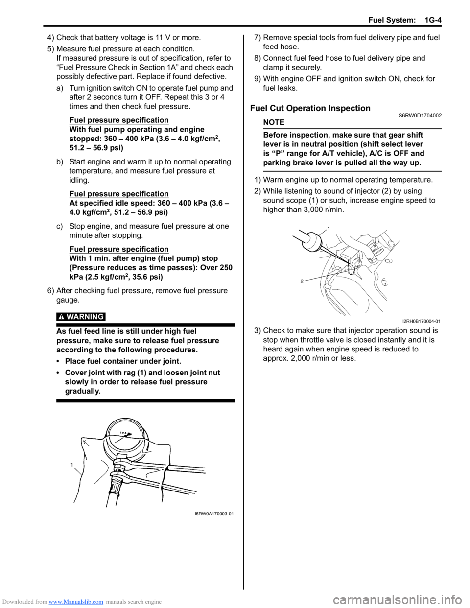
• Cover joint with rag (1) and loosen joint nut
slowly in order to release fuel pressure
gradually.
7) Remove special tools from fuel delivery pipe and fuel
feed hose.
8) Connect fuel feed hose to fuel delivery pipe and
clamp it securely.
9) With engine OFF and ignition switch ON, check for
fuel leaks.
Fuel Cut Operation InspectionS6RW0D1704002
NOTE
Before inspection, make sure that gear shift
lever is in neutral position (shift select lever
is “P” range for A/T vehicle), A/C is OFF and
parking brake lever is pulled all the way up.
1) Warm engine up to normal operating temperature.
2) While listening to sound of injector (2) by using
sound scope (1) or such, increase engine speed to
higher than 3,000 r/min.
3) Check to make sure that injector operation sound is
stop when throttle valve is closed instantly and it is
heard again when engine speed is reduced to
approx. 2,000 r/min or less.
I5RW0A170003-01
I2RH0B170004-01
Page 385 of 1556
Downloaded from www.Manualslib.com manuals search engine Fuel System: 1G-8
6) Start engine and run it until engine stops for lack of
fuel. Repeat cranking engine 2 – 3 times for about 3
seconds each time in order to dissipate fuel pressure
in lines. Fuel connections are now safe for servicing.
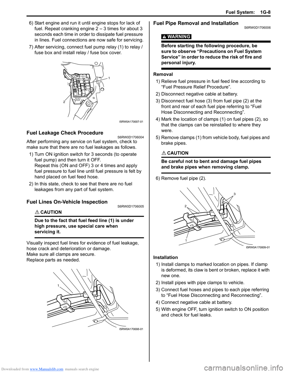
7) After servicing, connect fuel pump relay (1) to relay /
fuse box and install relay / fuse box cover.
Fuel Leakage Check ProcedureS6RW0D1706004
After performing any service on fuel system, check to
make sure that there are no fuel leakages as follows.
1) Turn ON ignition switch for 3 seconds (to operate
fuel pump) and then turn it OFF.
Repeat this (ON and OFF) 3 or 4 times and apply
fuel pressure to fuel line until fuel pressure is felt by
hand placed on fuel feed hose.
2) In this state, check to see that there are no fuel
leakages from any part of fuel system.
Fuel Lines On-Vehicle InspectionS6RW0D1706005
CAUTION!
Due to the fact that fuel feed line (1) is under
high pressure, use special care when
servicing it.
Visually inspect fuel lines for evidence of fuel leakage,
hose crack and deterioration or damage.
Make sure all clamps are secure.
Replace parts as needed.
Fuel Pipe Removal and InstallationS6RW0D1706006
WARNING!
Before starting the following procedure, be
sure to observe “Precautions on Fuel System
Service” in order to reduce the risk of fire and
personal injury.
Removal
1) Relieve fuel pressure in fuel feed line according to
“Fuel Pressure Relief Procedure”.
2) Disconnect negative cable at battery.
3) Disconnect fuel hose (3) from fuel pipe (2) at the
front and rear of each fuel pipe referring to “Fuel
Hose Disconnecting and Reconnecting”.
4) Mark the location of clamps (1) on fuel pipes (2), so
that the clamps can be reinstalled to where they
were.
5) Remove clamps (1) from vehicle body, fuel pipes and
brake pipes.
CAUTION!
Be careful not to bent and damage fuel pipes
and brake pipes when removing clamp.
6) Remove fuel pipe (2).
Installation
1) Install clamps to marked location on pipes. If clamp
is deformed, its claw is bent or broken, replace it with
new one.
2) Install pipes with pipe clamps to vehicle.
3) Connect fuel hoses and pipes to each pipe referring
to “Fuel Hose Disconnecting and Reconnecting”.
4) Connect negative cable at battery.
5) With engine OFF, turn ignition switch to ON position
and check for fuel leaks.
1
2
I5RW0A170007-01
1
I5RW0A170008-01
2
3
1
I5RW0A170009-01
Page 421 of 1556
Downloaded from www.Manualslib.com manuals search engine Charging System: 1J-7
1) Set parking brake and place automatic transaxle in
PARK (NEUTRAL on manual transaxle). Turn off
ignition, turn off lights and all other electrical loads.
2) Check electrolyte level. If it is below low level line,
add distilled water.
3) Attach end of one jumper cable to positive terminal
of booster battery and the other end of the same
cable to positive terminal of discharged battery. (Use
12-volt battery only to jump start engine).
4) Attach one end of the remaining negative cable to
negative terminal of booster battery, and the other
end to a solid engine ground (such as exhaust
manifold) at least 45 cm (18 in.) away from battery of
vehicle being started.
5) Start engine of vehicle with booster battery and turn
off electrical accessories. Then start engine of the
vehicle with discharged battery.
6) Disconnect jumper cables in the exact reverse order.
With Charging Equipment
CAUTION!
When jump starting engine with charging
equipment, be sure equipment used is 12-
volt and negative ground. Do not use 24-volt
charging equipment. Using such equipment
can cause serious damage to electrical
system or electronic parts.
Battery Dismounting and RemountingS6RW0D1A06002
Dismounting
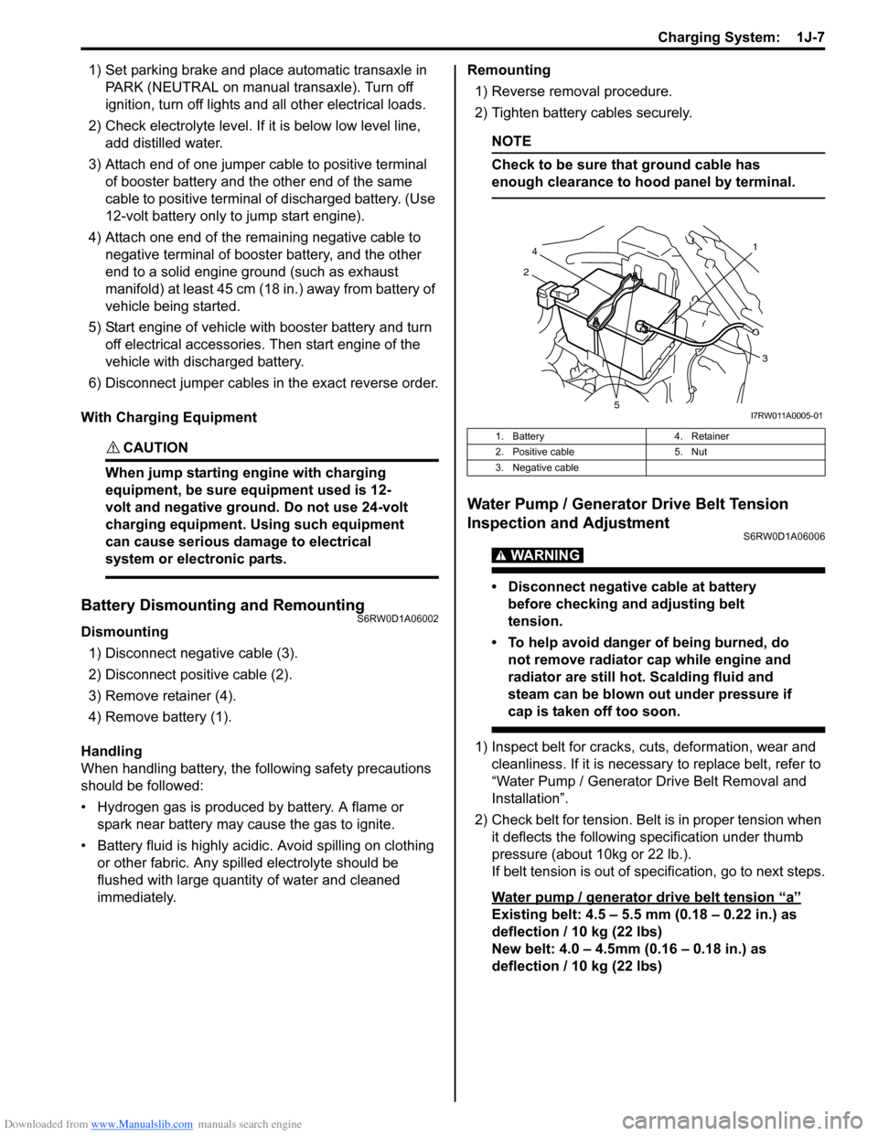
1) Disconnect negative cable (3).
2) Disconnect positive cable (2).
3) Remove retainer (4).
4) Remove battery (1).
Handling
When handling battery, the following safety precautions
should be followed:
• Hydrogen gas is produced by battery. A flame or
spark near battery may cause the gas to ignite.
• Battery fluid is highly acidic. Avoid spilling on clothing
or other fabric. Any spilled electrolyte should be
flushed with large quantity of water and cleaned
immediately.Remounting
1) Reverse removal procedure.
2) Tighten battery cables securely.
NOTE
Check to be sure that ground cable has
enough clearance to hood panel by terminal.
Water Pump / Generator Drive Belt Tension
Inspection and Adjustment
S6RW0D1A06006
WARNING!
• Disconnect negative cable at battery
before checking and adjusting belt
tension.
• To help avoid danger of being burned, do
not remove radiator cap while engine and
radiator are still hot. Scalding fluid and
steam can be blown out under pressure if
cap is taken off too soon.
1) Inspect belt for cracks, cuts, deformation, wear and
cleanliness. If it is necessary to replace belt, refer to
“Water Pump / Generator Drive Belt Removal and
Installation”.
2) Check belt for tension. Belt is in proper tension when
it deflects the following specification under thumb
pressure (about 10kg or 22 lb.).
If belt tension is out of specification, go to next steps.
Water pump / generator drive belt tension
“a”
Existing belt: 4.5 – 5.5 mm (0.18 – 0.22 in.) as
deflection / 10 kg (22 lbs)
New belt: 4.0 – 4.5mm (0.16 – 0.18 in.) as
deflection / 10 kg (22 lbs)
1. Battery 4. Retainer
2. Positive cable 5. Nut
3. Negative cable
21
4
3
5I7RW011A0005-01
Page 473 of 1556
Downloaded from www.Manualslib.com manuals search engine Wheels and Tires: 2D-4
Equipment manufacture’s recommendations
Radial Tire Lead / Pull DescriptionS6RW0D2401006
“Lead / Pull” is the deviation of the vehicle from a straight
path on a level road even with no pressure on the
steering wheel.
Lead is usually caused by the following conditions.
• Improper tire and wheel alignment.
• Uneven brake assemblies.
• Tire construction.
The way in which a tire is built can produce lead in a
vehicle. An example of this is placement of the belt. Off
center belts on radial tires can cause the tire to develop
a side force while rolling straight down the road. If one
side of the tire has a little larger diameter than the other,
the tire will tend to roll to one side. This will develop a
side force which can produce vehicle lead.
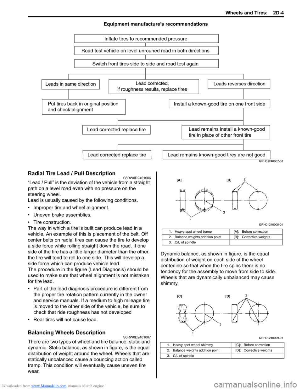
The procedure in the figure (Lead Diagnosis) should be
used to make sure that wheel alignment is not mistaken
for tire lead.
• Part of the lead diagnosis procedure is different from
the proper tire rotation pattern currently in the owner
and service manuals. If a medium to high mileage tire
is moved to the other side of the vehicle, be sure to
check that ride roughness has not developed
• Rear tires will not cause lead.
Balancing Wheels DescriptionS6RW0D2401007
There are two types of wheel and tire balance: static and
dynamic. Static balance, as shown in figure, is the equal
distribution of weight around the wheel. Wheels that are
statically unbalanced cause a bouncing action called
tramp. This condition will eventually cause uneven tire
wear.Dynamic balance, as shown in figure, is the equal
distribution of weight on each side of the wheel
centerline so that when the tire spins there is no
tendency for the assembly to move from side to side.
Wheels that are dynamically unbalanced may cause
shimmy.
Inflate tires to recommended pressure
Road test vehicle on level unrouned road in both directions
Switch front tires side to side and road test again
Lead corrected,
if roughness results, replace tiresLeads in same directionLeads reverses direction
Put tires back in original position
and check alignmentInstall a known-good tire on one front side
Lead remains install a known-good
tire in place of other front tire
Lead remains known-good tires are not goodLead corrected replace tire
Lead corrected replace tire
I2RH01240007-01
1. Heavy spot wheel tramp [A]: Before correction
2. Balance weights addition point [B]: Corrective weights
3. C/L of spindle
1. Heavy spot wheel shimmy [C]: Before correction
2. Balance weights addition point [D]: Corrective weights
3. C/L of spindle
I2RH01240008-01
I2RH01240009-01
Page 482 of 1556
Downloaded from www.Manualslib.com manuals search engine 3A-3 Drive Shaft / Axle: Front
Front Drive Shaft Assembly On-Vehicle
Inspection
S6RW0D3116002
• Check boots for breakage or deterioration.
• Check wheel side joint for rattle or smooth rotation.
• Check differential side (or center shaft side) joint for
smooth rotation.
If any abnormality is found, replace.
Front Drive Shaft Assembly Removal and
Installation
S6RW0D3116003
Removal
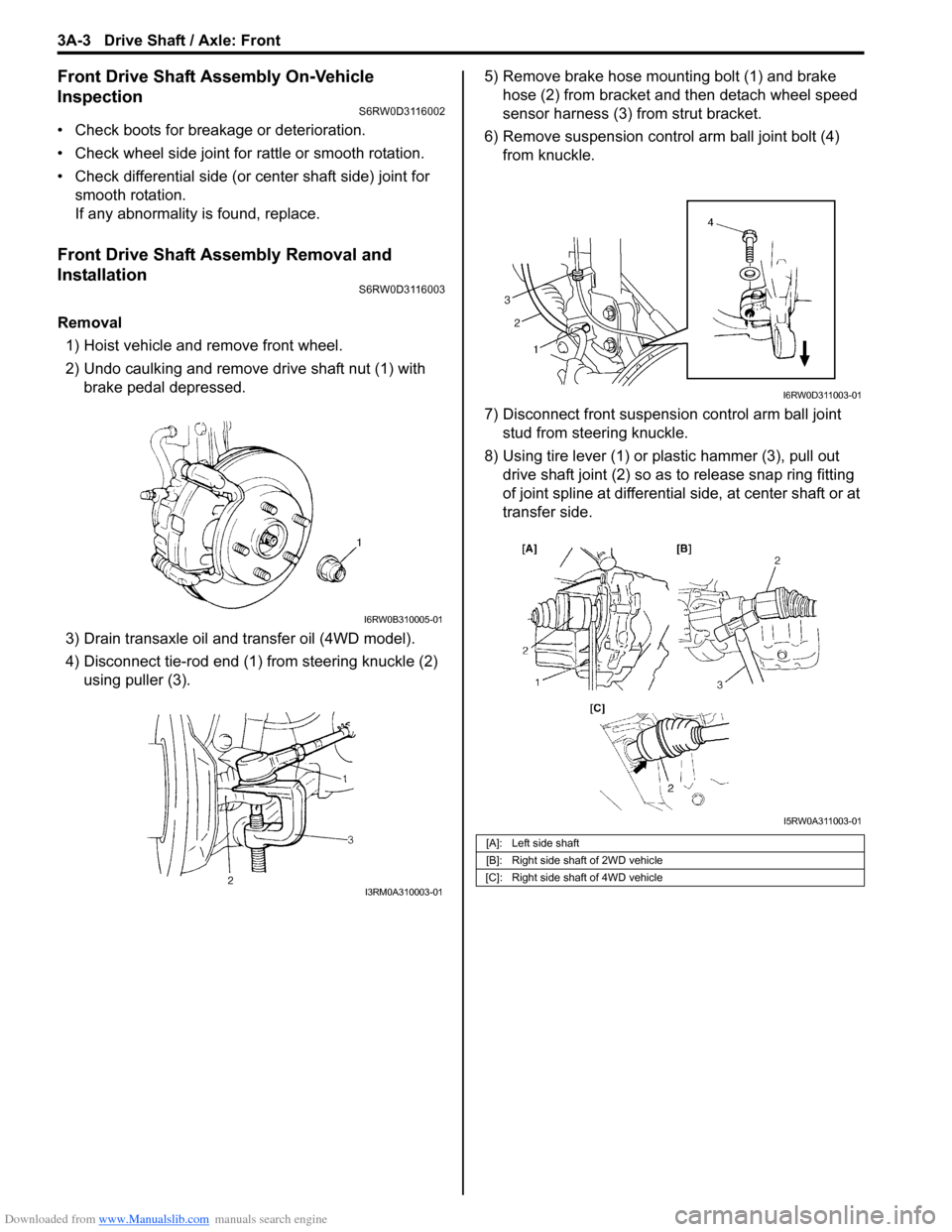
1) Hoist vehicle and remove front wheel.
2) Undo caulking and remove drive shaft nut (1) with
brake pedal depressed.
3) Drain transaxle oil and transfer oil (4WD model).
4) Disconnect tie-rod end (1) from steering knuckle (2)
using puller (3).5) Remove brake hose mounting bolt (1) and brake
hose (2) from bracket and then detach wheel speed
sensor harness (3) from strut bracket.
6) Remove suspension control arm ball joint bolt (4)
from knuckle.
7) Disconnect front suspension control arm ball joint
stud from steering knuckle.
8) Using tire lever (1) or plastic hammer (3), pull out
drive shaft joint (2) so as to release snap ring fitting
of joint spline at differential side, at center shaft or at
transfer side.
I6RW0B310005-01
I3RM0A310003-01
[A]: Left side shaft
[B]: Right side shaft of 2WD vehicle
[C]: Right side shaft of 4WD vehicle
I6RW0D311003-01
I5RW0A311003-01
Page 576 of 1556
Downloaded from www.Manualslib.com manuals search engine 4A-5 Brake Control System and Diagnosis:
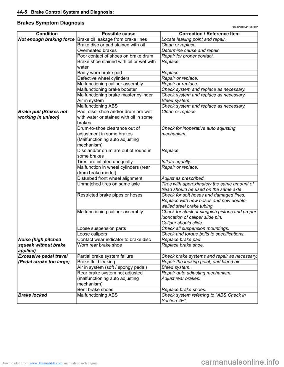
Brakes Symptom DiagnosisS6RW0D4104002
Condition Possible cause Correction / Reference Item
Not enough braking forceBrake oil leakage from brake linesLocate leaking point and repair.
Brake disc or pad stained with oilClean or replace.
Overheated brakesDetermine cause and repair.
Poor contact of shoes on brake drumRepair for proper contact.
Brake shoe stained with oil or wet with
waterReplace.
Badly worn brake padReplace.
Defective wheel cylindersRepair or replace.
Malfunctioning caliper assemblyRepair or replace.
Malfunctioning brake boosterCheck system and replace as necessary.
Malfunctioning brake master cylinderCheck system and replace as necessary.
Air in systemBleed system.
Malfunctioning ABSCheck system and replace as necessary.
Brake pull (Brakes not
working in unison)Pad, disc, shoe and/or drum are wet
with water or stained with oil in some
brakesClean or replace.
Drum-to-shoe clearance out of
adjustment in some brakes
(Malfunctioning auto adjusting
mechanism) Check for inoperative auto adjusting
mechanism.
Disc and/or drum are out of round in
some brakesReplace.
Tires are inflated unequallyInflate equally.
Malfunction in wheel cylinders (rear
drum brake model)Repair or replace.
Disturbed front wheel alignmentAdjust as prescribed.
Unmatched tires on same axleTires with approximately the same amount of
tread should be used on the same axle.
Restricted brake pipes or hosesCheck for soft hoses and damaged lines.
Replace with new hoses and new double-
walled steel brake tubing.
Malfunctioning caliper assemblyCheck for stuck or sluggish pistons and proper
lubrication of caliper slide pin.
Caliper should slide.
Loose suspension partsCheck all suspension mountings.
Loose calipersCheck and torque bolts to specifications.
Noise (high pitched
squeak without brake
applied)Contact wear indicator to brake discReplace brake pad.
Worn rear brake shoeReplace brake shoe.
Excessive pedal travel
(Pedal stroke too large)Partial brake system failureCheck brake systems and repair as necessary.
Brake fluid leakingRepair the leaking point, and bleed air.
Air in system (soft / spongy pedal)Bleed system.
Rear brake system not adjusted
(malfunctioning auto adjusting
mechanism)Repair auto adjusting mechanism.
Adjust rear brakes.
Bent brake shoesReplace brake shoes.
Brake locked Malfunctioning ABSCheck system referring to “ABS Check in
Section 4E”.