check engine light SUZUKI SX4 2006 1.G Service User Guide
[x] Cancel search | Manufacturer: SUZUKI, Model Year: 2006, Model line: SX4, Model: SUZUKI SX4 2006 1.GPages: 1556, PDF Size: 37.31 MB
Page 76 of 1556
Downloaded from www.Manualslib.com manuals search engine 1A-26 Engine General Information and Diagnosis:
• The MIL is turned on when the ECM and/or
TCM detect malfunction(s). Each ECM and
TCM stores diagnostic information as the
diagnostic trouble code (DTC) in its
memory and outputs the DTC to the scan
tool.
Therefore, check both of the ECM and TCM
for any DTC with the scan tool because the
DTC stored in ECM and TCM is not read
and displayed at a time. However, each of
the ECM and TCM needs not to be checked
with the generic scan tool because the
DTC stored in ECM and TCM is read and
displayed at a time.
1) Prepare CAN communication OBD generic scan tool
or SUZUKI scan tool.
Special tool
(A): SUZUKI scan tool (SUZUKI-SDT)
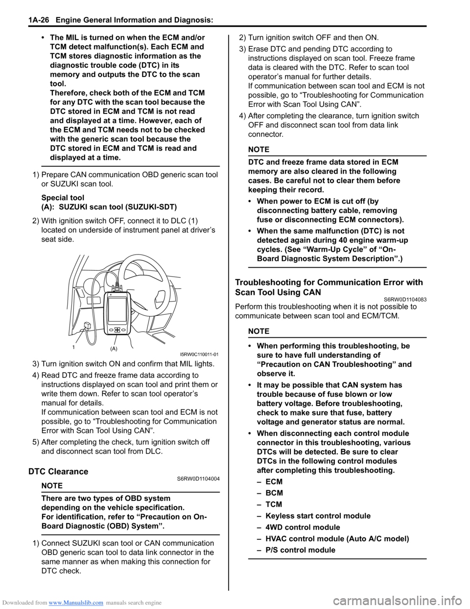
2) With ignition switch OFF, connect it to DLC (1)
located on underside of instrument panel at driver’s
seat side.
3) Turn ignition switch ON and confirm that MIL lights.
4) Read DTC and freeze frame data according to
instructions displayed on scan tool and print them or
write them down. Refer to scan tool operator’s
manual for details.
If communication between scan tool and ECM is not
possible, go to “Troubleshooting for Communication
Error with Scan Tool Using CAN”.
5) After completing the check, turn ignition switch off
and disconnect scan tool from DLC.
DTC ClearanceS6RW0D1104004
NOTE
There are two types of OBD system
depending on the vehicle specification.
For identification, refer to “Precaution on On-
Board Diagnostic (OBD) System”.
1) Connect SUZUKI scan tool or CAN communication
OBD generic scan tool to data link connector in the
same manner as when making this connection for
DTC check.2) Turn ignition switch OFF and then ON.
3) Erase DTC and pending DTC according to
instructions displayed on scan tool. Freeze frame
data is cleared with the DTC. Refer to scan tool
operator’s manual for further details.
If communication between scan tool and ECM is not
possible, go to “Troubleshooting for Communication
Error with Scan Tool Using CAN”.
4) After completing the clearance, turn ignition switch
OFF and disconnect scan tool from data link
connector.
NOTE
DTC and freeze frame data stored in ECM
memory are also cleared in the following
cases. Be careful not to clear them before
keeping their record.
• When power to ECM is cut off (by
disconnecting battery cable, removing
fuse or disconnecting ECM connectors).
• When the same malfunction (DTC) is not
detected again during 40 engine warm-up
cycles. (See “Warm-Up Cycle” of “On-
Board Diagnostic System Description”.)
Troubleshooting for Communication Error with
Scan Tool Using CAN
S6RW0D1104083
Perform this troubleshooting when it is not possible to
communicate between scan tool and ECM/TCM.
NOTE
• When performing this troubleshooting, be
sure to have full understanding of
“Precaution on CAN Troubleshooting” and
observe it.
• It may be possible that CAN system has
trouble because of fuse blown or low
battery voltage. Before troubleshooting,
check to make sure that fuse, battery
voltage and generator status are normal.
• When disconnecting each control module
connector in this troubleshooting, various
DTCs will be detected. Be sure to clear
DTCs in the following control modules
after completing this troubleshooting.
–ECM
–BCM
–TCM
– Keyless start control module
– 4WD control module
– HVAC control module (Auto A/C model)
– P/S control module
(A) 1I5RW0C110011-01
Page 88 of 1556
Downloaded from www.Manualslib.com manuals search engine 1A-38 Engine General Information and Diagnosis:
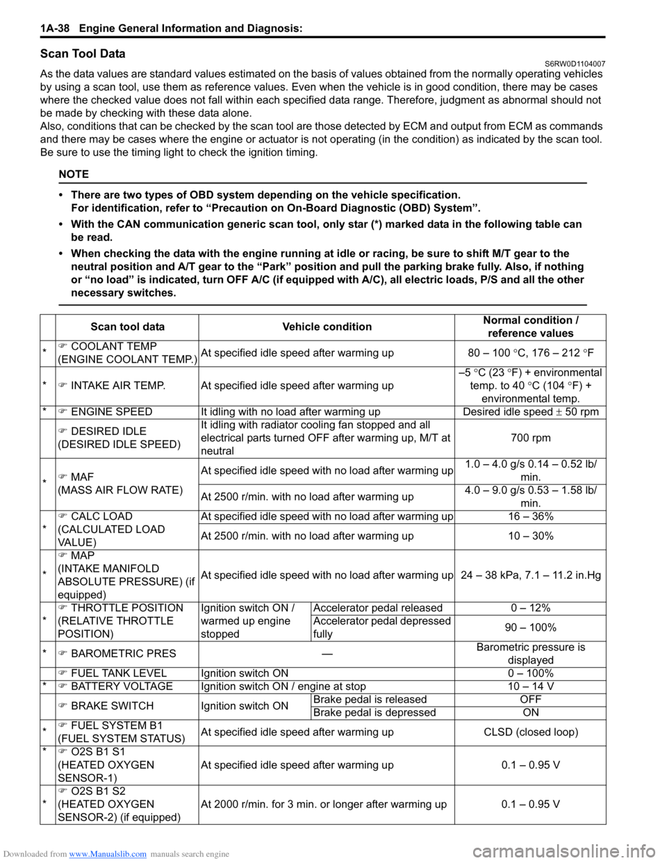
Scan Tool DataS6RW0D1104007
As the data values are standard values estimated on the basis of values obtained from the normally operating vehicles
by using a scan tool, use them as reference values. Even when the vehicle is in good condition, there may be cases
where the checked value does not fall within each specified data range. Therefore, judgment as abnormal should not
be made by checking with these data alone.
Also, conditions that can be checked by the scan tool are those detected by ECM and output from ECM as commands
and there may be cases where the engine or actuator is not operating (in the condition) as indicated by the scan tool.
Be sure to use the timing light to check the ignition timing.
NOTE
• There are two types of OBD system depending on the vehicle specification.
For identification, refer to “Precaution on On-Board Diagnostic (OBD) System”.
• With the CAN communication generic scan tool, only star (*) marked data in the following table can
be read.
• When checking the data with the engine running at idle or racing, be sure to shift M/T gear to the
neutral position and A/T gear to the “Park” position and pull the parking brake fully. Also, if nothing
or “no load” is indicated, turn OFF A/C (if equipped with A/C), all electric loads, P/S and all the other
necessary switches.
Scan tool data Vehicle conditionNormal condition /
reference values
*�) COOLANT TEMP
(ENGINE COOLANT TEMP.)At specified idle speed after warming up 80 – 100 °C, 176 – 212 °F
*�) INTAKE AIR TEMP. At specified idle speed after warming up–5 °C (23 °F) + environmental
temp. to 40 °C (104 °F) +
environmental temp.
*�) ENGINE SPEED It idling with no load after warming up Desired idle speed ± 50 rpm
�) DESIRED IDLE
(DESIRED IDLE SPEED)It idling with radiator cooling fan stopped and all
electrical parts turned OFF after warming up, M/T at
neutral700 rpm
*�) MAF
(MASS AIR FLOW RATE)At specified idle speed with no load after warming up1.0 – 4.0 g/s 0.14 – 0.52 lb/
min.
At 2500 r/min. with no load after warming up4.0 – 9.0 g/s 0.53 – 1.58 lb/
min.
*�) CALC LOAD
(CALCULATED LOAD
VA L U E )At specified idle speed with no load after warming up 16 – 36%
At 2500 r/min. with no load after warming up 10 – 30%
*�) MAP
(INTAKE MANIFOLD
ABSOLUTE PRESSURE) (if
equipped)At specified idle speed with no load after warming up 24 – 38 kPa, 7.1 – 11.2 in.Hg
*�) THROTTLE POSITION
(RELATIVE THROTTLE
POSITION)Ignition switch ON /
warmed up engine
stoppedAccelerator pedal released 0 – 12%
Accelerator pedal depressed
fully90 – 100%
*�) BAROMETRIC PRES —Barometric pressure is
displayed
�) FUEL TANK LEVEL Ignition switch ON 0 – 100%
*�) BATTERY VOLTAGE Ignition switch ON / engine at stop 10 – 14 V
�) BRAKE SWITCH Ignition switch ONBrake pedal is released OFF
Brake pedal is depressed ON
*�) FUEL SYSTEM B1
(FUEL SYSTEM STATUS)At specified idle speed after warming up CLSD (closed loop)
*�) O2S B1 S1
(HEATED OXYGEN
SENSOR-1)At specified idle speed after warming up 0.1 – 0.95 V
*�)
O2S B1 S2
(HEATED OXYGEN
SENSOR-2) (if equipped)At 2000 r/min. for 3 min. or longer after warming up 0.1 – 0.95 V
Page 92 of 1556
Downloaded from www.Manualslib.com manuals search engine 1A-42 Engine General Information and Diagnosis:
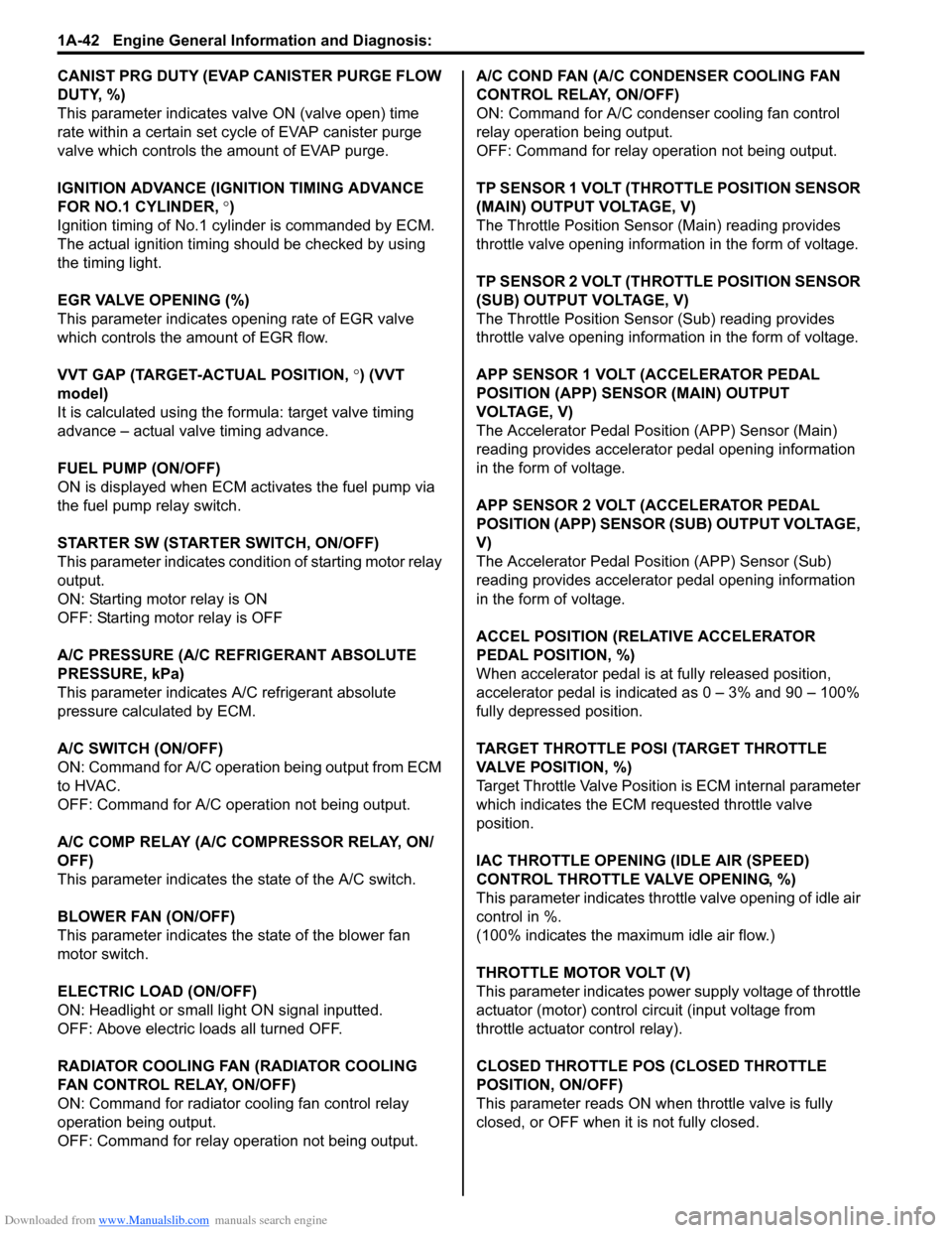
CANIST PRG DUTY (EVAP CANISTER PURGE FLOW
DUTY, %)
This parameter indicates valve ON (valve open) time
rate within a certain set cycle of EVAP canister purge
valve which controls the amount of EVAP purge.
IGNITION ADVANCE (IGNITION TIMING ADVANCE
FOR NO.1 CYLINDER, °)
Ignition timing of No.1 cylinder is commanded by ECM.
The actual ignition timing should be checked by using
the timing light.
EGR VALVE OPENING (%)
This parameter indicates opening rate of EGR valve
which controls the amount of EGR flow.
VVT GAP (TARGET-ACTUAL POSITION, °) (VVT
model)
It is calculated using the formula: target valve timing
advance – actual valve timing advance.
FUEL PUMP (ON/OFF)
ON is displayed when ECM activates the fuel pump via
the fuel pump relay switch.
STARTER SW (STARTER SWITCH, ON/OFF)
This parameter indicates condition of starting motor relay
output.
ON: Starting motor relay is ON
OFF: Starting motor relay is OFF
A/C PRESSURE (A/C REFRIGERANT ABSOLUTE
PRESSURE, kPa)
This parameter indicates A/C refrigerant absolute
pressure calculated by ECM.
A/C SWITCH (ON/OFF)
ON: Command for A/C operation being output from ECM
to HVAC.
OFF: Command for A/C operation not being output.
A/C COMP RELAY (A/C COMPRESSOR RELAY, ON/
OFF)
This parameter indicates the state of the A/C switch.
BLOWER FAN (ON/OFF)
This parameter indicates the state of the blower fan
motor switch.
ELECTRIC LOAD (ON/OFF)
ON: Headlight or small light ON signal inputted.
OFF: Above electric loads all turned OFF.
RADIATOR COOLING FAN (RADIATOR COOLING
FAN CONTROL RELAY, ON/OFF)
ON: Command for radiator cooling fan control relay
operation being output.
OFF: Command for relay operation not being output.A/C COND FAN (A/C CONDENSER COOLING FAN
CONTROL RELAY, ON/OFF)
ON: Command for A/C condenser cooling fan control
relay operation being output.
OFF: Command for relay operation not being output.
TP SENSOR 1 VOLT (THROTTLE POSITION SENSOR
(MAIN) OUTPUT VOLTAGE, V)
The Throttle Position Sensor (Main) reading provides
throttle valve opening information in the form of voltage.
TP SENSOR 2 VOLT (THROTTLE POSITION SENSOR
(SUB) OUTPUT VOLTAGE, V)
The Throttle Position Sensor (Sub) reading provides
throttle valve opening information in the form of voltage.
APP SENSOR 1 VOLT (ACCELERATOR PEDAL
POSITION (APP) SENSOR (MAIN) OUTPUT
VOLTAGE, V)
The Accelerator Pedal Position (APP) Sensor (Main)
reading provides accelerator pedal opening information
in the form of voltage.
APP SENSOR 2 VOLT (ACCELERATOR PEDAL
POSITION (APP) SENSOR (SUB) OUTPUT VOLTAGE,
V)
The Accelerator Pedal Position (APP) Sensor (Sub)
reading provides accelerator pedal opening information
in the form of voltage.
ACCEL POSITION (RELATIVE ACCELERATOR
PEDAL POSITION, %)
When accelerator pedal is at fully released position,
accelerator pedal is indicated as 0 – 3% and 90 – 100%
fully depressed position.
TARGET THROTTLE POSI (TARGET THROTTLE
VALVE POSITION, %)
Target Throttle Valve Position is ECM internal parameter
which indicates the ECM requested throttle valve
position.
IAC THROTTLE OPENING (IDLE AIR (SPEED)
CONTROL THROTTLE VALVE OPENING, %)
This parameter indicates throttle valve opening of idle air
control in %.
(100% indicates the maximum idle air flow.)
THROTTLE MOTOR VOLT (V)
This parameter indicates power supply voltage of throttle
actuator (motor) control circuit (input voltage from
throttle actuator control relay).
CLOSED THROTTLE POS (CLOSED THROTTLE
POSITION, ON/OFF)
This parameter reads ON when throttle valve is fully
closed, or OFF when it is not fully closed.
Page 103 of 1556
Downloaded from www.Manualslib.com manuals search engine Engine General Information and Diagnosis: 1A-53
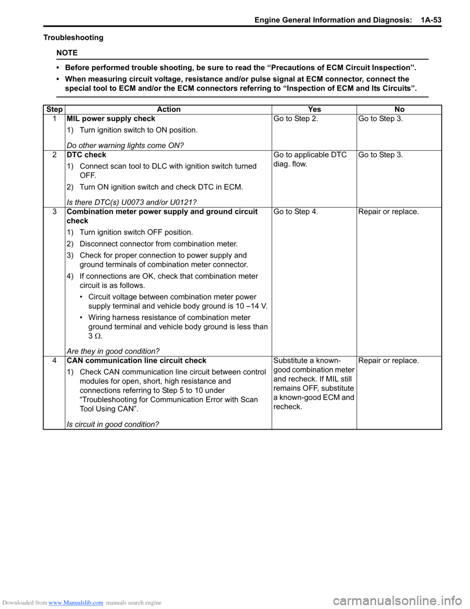
Troubleshooting
NOTE
• Before performed trouble shooting, be sure to read the “Precautions of ECM Circuit Inspection”.
• When measuring circuit voltage, resistance and/or pulse signal at ECM connector, connect the
special tool to ECM and/or the ECM connectors referring to “Inspection of ECM and Its Circuits”.
Step Action Yes No
1MIL power supply check
1) Turn ignition switch to ON position.
Do other warning lights come ON?Go to Step 2. Go to Step 3.
2DTC check
1) Connect scan tool to DLC with ignition switch turned
OFF.
2) Turn ON ignition switch and check DTC in ECM.
Is there DTC(s) U0073 and/or U0121?Go to applicable DTC
diag. flow.Go to Step 3.
3Combination meter power supply and ground circuit
check
1) Turn ignition switch OFF position.
2) Disconnect connector from combination meter.
3) Check for proper connection to power supply and
ground terminals of combination meter connector.
4) If connections are OK, check that combination meter
circuit is as follows.
• Circuit voltage between combination meter power
supply terminal and vehicle body ground is 10 –14 V.
• Wiring harness resistance of combination meter
ground terminal and vehicle body ground is less than
3 Ω.
Are they in good condition?Go to Step 4. Repair or replace.
4CAN communication line circuit check
1) Check CAN communication line circuit between control
modules for open, short, high resistance and
connections referring to Step 5 to 10 under
“Troubleshooting for Communication Error with Scan
Tool Using CAN”.
Is circuit in good condition?Substitute a known-
good combination meter
and recheck. If MIL still
remains OFF, substitute
a known-good ECM and
recheck.Repair or replace.
Page 178 of 1556
Downloaded from www.Manualslib.com manuals search engine 1A-128 Engine General Information and Diagnosis:
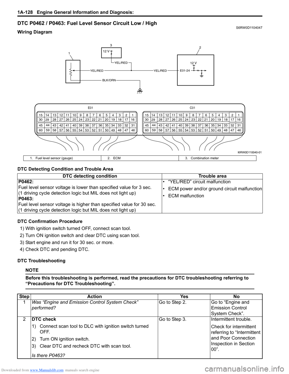
DTC P0462 / P0463: Fuel Level Sensor Circuit Low / HighS6RW0D1104047
Wiring Diagram
DTC Detecting Condition and Trouble Area
DTC Confirmation Procedure
1) With ignition switch turned OFF, connect scan tool.
2) Turn ON ignition switch and clear DTC using scan tool.
3) Start engine and run it for 30 sec. or more.
4) Check DTC and pending DTC.
DTC Troubleshooting
NOTE
Before this troubleshooting is performed, read the precautions for DTC troubleshooting referring to
“Precautions for DTC Troubleshooting”.
E01C01
3 4
18 19 5 6 7 10 11
17 20
47 46 49 50 51 21 22
5216 259
24 14
29
55 57 54 53 59
60 582
26 27 28 15
30
56 4832 31 34 35 36 37 40 42 39 38 44
45 43 41 331 12 13
238 3 4
18 19 5 6 7 10 11
17 20
47 46 49 50 51 21 22
5216 259
24 14
29
55 57 54 53 59
60 582
26 27 28 15
30
56 4832 31 34 35 36 37 40 42 39 38 44
45 43 41 331 12 13
238
12 V
13
2
E01-24
BLK/ORN
YEL/REDYEL/RED
12 V
YEL/RED
I6RW0D110040-01
1. Fuel level sensor (gauge) 2. ECM 3. Combination meter
DTC detecting condition Trouble area
P0462:
Fuel level sensor voltage is lower than specified value for 3 sec.
(1 driving cycle detection logic but MIL does not light up)
P0463:
Fuel level sensor voltage is higher than specified value for 30 sec.
(1 driving cycle detection logic but MIL does not light up)• “YEL/RED” circuit malfunction
• ECM power and/or ground circuit malfunction
• ECM malfunction
Step Action Yes No
1Was “Engine and Emission Control System Check”
performed?Go to Step 2. Go to “Engine and
Emission Control
System Check”.
2DTC check
1) Connect scan tool to DLC with ignition switch turned
OFF.
2) Turn ON ignition switch.
3) Clear DTC and recheck DTC with scan tool.
Is there P0463?Go to Step 3. Intermittent trouble.
Check for intermittent
referring to “Intermittent
and Poor Connection
Inspection in Section
00”.
Page 181 of 1556
Downloaded from www.Manualslib.com manuals search engine Engine General Information and Diagnosis: 1A-131
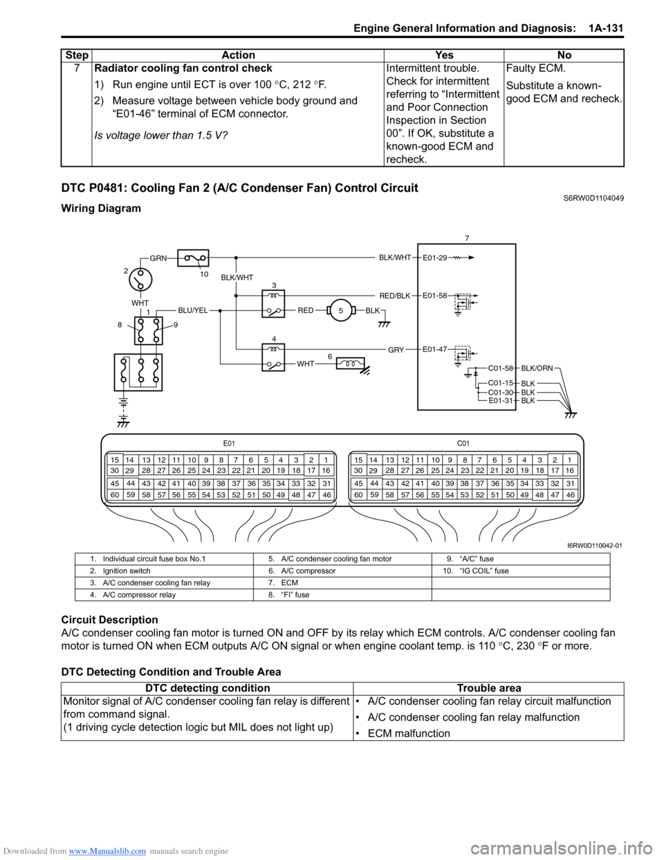
DTC P0481: Cooling Fan 2 (A/C Condenser Fan) Control CircuitS6RW0D1104049
Wiring Diagram
Circuit Description
A/C condenser cooling fan motor is turned ON and OFF by its relay which ECM controls. A/C condenser cooling fan
motor is turned ON when ECM outputs A/C ON signal or when engine coolant temp. is 110 °C, 230 °F or more.
DTC Detecting Condition and Trouble Area7Radiator cooling fan control check
1) Run engine until ECT is over 100 °C, 212 °F.
2) Measure voltage between vehicle body ground and
“E01-46” terminal of ECM connector.
Is voltage lower than 1.5 V?Intermittent trouble.
Check for intermittent
referring to “Intermittent
and Poor Connection
Inspection in Section
00”. If OK, substitute a
known-good ECM and
recheck.Faulty ECM.
Substitute a known-
good ECM and recheck. Step Action Yes No
E01C01
3 4
18 19 5 6 7 10 11
17 20
47 46 49 50 51 21 22
5216 259
24 14
29
55 57 54 53 59
60 582
26 27 28 15
30
56 4832 31 34 35 36 37 40 42 39 38 44
45 43 41 331 12 13
238 3 4
18 19 5 6 7 10 11
17 20
47 46 49 50 51 21 22
5216 259
24 14
29
55 57 54 53 59
60 582
26 27 28 15
30
56 4832 31 34 35 36 37 40 42 39 38 44
45 43 41 331 12 13
238
BLK/WHT
WHT
1
GRN
27
E01-29
10
89
REDBLK
3
5BLK/WHT
RED/BLKE01-58
WHT
4E01-47 GRY
BLU/YEL
6
C01-58
C01-15 C01-30
BLK/ORN
BLKBLKE01-31BLK
I6RW0D110042-01
1. Individual circuit fuse box No.1 5. A/C condenser cooling fan motor 9. “A/C” fuse
2. Ignition switch 6. A/C compressor 10. “IG COIL” fuse
3. A/C condenser cooling fan relay 7. ECM
4. A/C compressor relay 8. “FI” fuse
DTC detecting condition Trouble area
Monitor signal of A/C condenser cooling fan relay is different
from command signal.
(1 driving cycle detection logic but MIL does not light up)• A/C condenser cooling fan relay circuit malfunction
• A/C condenser cooling fan relay malfunction
• ECM malfunction
Page 186 of 1556
Downloaded from www.Manualslib.com manuals search engine 1A-136 Engine General Information and Diagnosis:
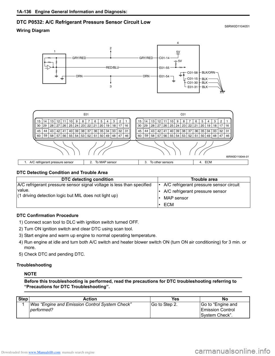
DTC P0532: A/C Refrigerant Pressure Sensor Circuit LowS6RW0D1104051
Wiring Diagram
DTC Detecting Condition and Trouble Area
DTC Confirmation Procedure
1) Connect scan tool to DLC with ignition switch turned OFF.
2) Turn ON ignition switch and clear DTC using scan tool.
3) Start engine and warm up engine to normal operating temperature.
4) Run engine at idle and turn both A/C switch and heater blower switch ON (turn ON air conditioning) for 3 min. or
more.
5) Check DTC and pending DTC.
Troubleshooting
NOTE
Before this troubleshooting is performed, read the precautions for DTC troubleshooting referring to
“Precautions for DTC Troubleshooting”.
E01C01
3 4
18 19 5 6 7 10 11
17 20
47 46 49 50 51 21 22
5216 259
24 14
29
55 57 54 53 59
60 582
26 27 28 15
30
56 4832 31 34 35 36 37 40 42 39 38 44
45 43 41 331 12 13
238 3 4
18 19 5 6 7 10 11
17 20
47 46 49 50 51 21 22
5216 259
24 14
29
55 57 54 53 59
60 582
26 27 28 15
30
56 4832 31 34 35 36 37 40 42 39 38 44
45 43 41 331 12 13
238
4
C01-58
C01-15 C01-30
BLK/ORN
BLKBLK
12
3
GRY/REDGRY/RED
ORNORN
5V
5VC01-14
E01-55
E01-54
RED/BLU
E01-31 BLK
I6RW0D110044-01
1. A/C refrigerant pressure sensor 2. To MAP sensor 3. To other sensors 4. ECM
DTC detecting condition Trouble area
A/C refrigerant pressure sensor signal voltage is less than specified
value.
(1 driving detection logic but MIL does not light up)• A/C refrigerant pressure sensor circuit
• A/C refrigerant pressure sensor
• MAP sensor
•ECM
Step Action Yes No
1Was “Engine and Emission Control System Check”
performed?Go to Step 2. Go to “Engine and
Emission Control
System Check”.
Page 188 of 1556
Downloaded from www.Manualslib.com manuals search engine 1A-138 Engine General Information and Diagnosis:
DTC P0533: A/C Refrigerant Pressure Sensor Circuit HighS6RW0D1104052
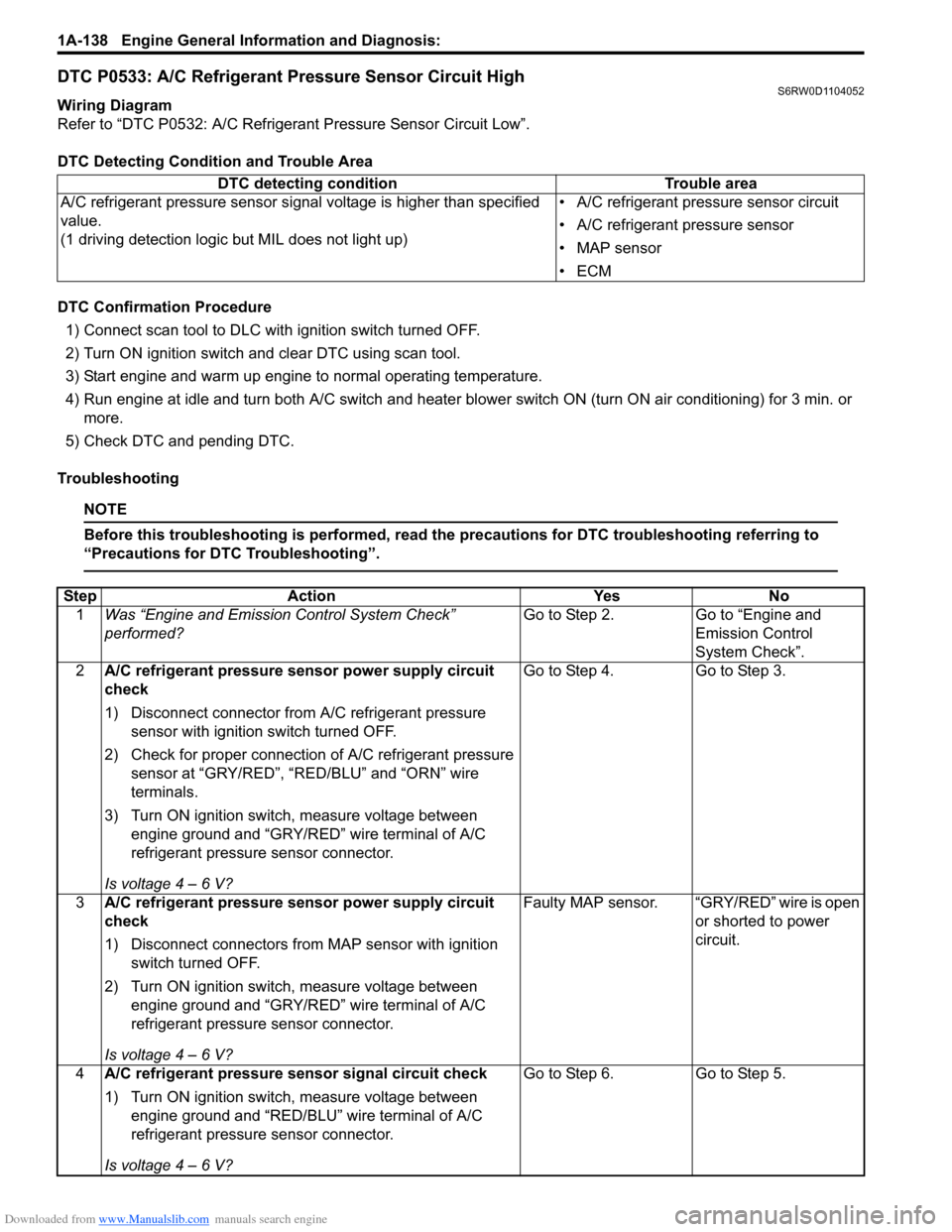
Wiring Diagram
Refer to “DTC P0532: A/C Refrigerant Pressure Sensor Circuit Low”.
DTC Detecting Condition and Trouble Area
DTC Confirmation Procedure
1) Connect scan tool to DLC with ignition switch turned OFF.
2) Turn ON ignition switch and clear DTC using scan tool.
3) Start engine and warm up engine to normal operating temperature.
4) Run engine at idle and turn both A/C switch and heater blower switch ON (turn ON air conditioning) for 3 min. or
more.
5) Check DTC and pending DTC.
Troubleshooting
NOTE
Before this troubleshooting is performed, read the precautions for DTC troubleshooting referring to
“Precautions for DTC Troubleshooting”.
DTC detecting condition Trouble area
A/C refrigerant pressure sensor signal voltage is higher than specified
value.
(1 driving detection logic but MIL does not light up)• A/C refrigerant pressure sensor circuit
• A/C refrigerant pressure sensor
• MAP sensor
•ECM
Step Action Yes No
1Was “Engine and Emission Control System Check”
performed?Go to Step 2. Go to “Engine and
Emission Control
System Check”.
2A/C refrigerant pressure sensor power supply circuit
check
1) Disconnect connector from A/C refrigerant pressure
sensor with ignition switch turned OFF.
2) Check for proper connection of A/C refrigerant pressure
sensor at “GRY/RED”, “RED/BLU” and “ORN” wire
terminals.
3) Turn ON ignition switch, measure voltage between
engine ground and “GRY/RED” wire terminal of A/C
refrigerant pressure sensor connector.
Is voltage 4 – 6 V?Go to Step 4. Go to Step 3.
3A/C refrigerant pressure sensor power supply circuit
check
1) Disconnect connectors from MAP sensor with ignition
switch turned OFF.
2) Turn ON ignition switch, measure voltage between
engine ground and “GRY/RED” wire terminal of A/C
refrigerant pressure sensor connector.
Is voltage 4 – 6 V?Faulty MAP sensor. “GRY/RED” wire is open
or shorted to power
circuit.
4A/C refrigerant pressure sensor signal circuit check
1) Turn ON ignition switch, measure voltage between
engine ground and “RED/BLU” wire terminal of A/C
refrigerant pressure sensor connector.
Is voltage 4 – 6 V?Go to Step 6. Go to Step 5.
Page 189 of 1556

Downloaded from www.Manualslib.com manuals search engine Engine General Information and Diagnosis: 1A-139
DTC P0601 / P0602 / P0607: Internal Control Module Memory Check Sum Error / Control Module
Programming Error / Control Module Performance
S6RW0D1104053
System Description
Internal control module is installed in ECM.
DTC Detecting Condition and Trouble Area
DTC Confirmation Procedure
1) Connect scan tool to DLC with ignition switch turned OFF.
2) Turn ON ignition switch and clear DTC, pending DTC and freeze frame data by using scan tool.
3) Start engine and run it at idle if possible.
4) Check DTC and pending DTC by using scan tool.5A/C refrigerant pressure sensor signal circuit check
1) Disconnect connectors from ECM with ignition switch
turned OFF.
2) Measure resistance between “RED/BLU” wire terminal of
A/C refrigerant pressure sensor connector and “E01-55”
terminal of ECM connector.
Is resistance below 2
Ω?“RED/BLU” wire is
shorted to power supply
circuit.“RED/BLU” wire is open
or high resistance
circuit.
6A/C refrigerant pressure sensor ground circuit check
1) Turn OFF ignition switch, measure resistance between
engine ground and “ORN” wire terminal of A/C
refrigerant pressure sensor connector.
Is resistance below 5
Ω?Go to Step 8. Go to Step 7.
7ECM ground circuit check
1) Remove ECM from its bracket with ECM connectors
connected.
2) Measure resistance between engine ground and “E01-
54” terminal of ECM connector.
Is resistance below 5
Ω?“ORN” wire is open or
high resistance circuit.ECM grounds “C01-58”,
“C01-15”, “C01-30” and/
or “E01-31” is open or
high resistance circuit.
8A/C refrigerant pressure sensor check
1) Check A/C refrigerant pressure sensor referring to “A/C
Refrigerant Pressure Sensor and Its Circuit Inspection in
Section 7B” or “A/C Refrigerant Pressure Sensor and Its
Circuit Inspection in Section 7B”.
Is it good condition?Substitute a known-
good ECM and recheck.Faulty A/C refrigerant
pressure sensor. Step Action Yes No
DTC detecting condition Trouble area
DTC P0601:
Data write error or check sum error
(1 driving cycle detection logic)
DTC P0602:
Data programming error
(1 driving cycle detection logic but MIL does not light up)
DTC P0607:
Data programming error
(1 driving cycle detection logic)ECM
Page 217 of 1556
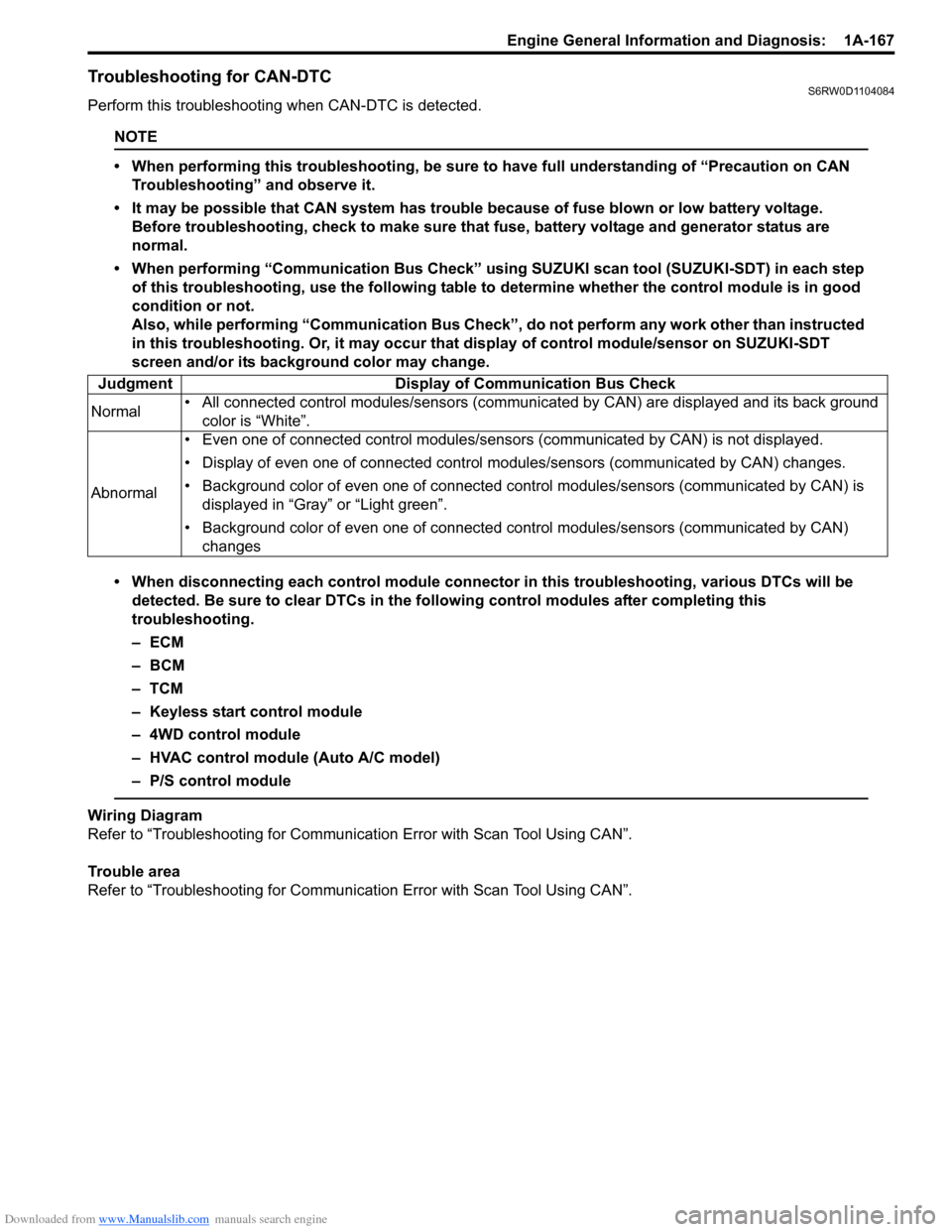
Downloaded from www.Manualslib.com manuals search engine Engine General Information and Diagnosis: 1A-167
Troubleshooting for CAN-DTCS6RW0D1104084
Perform this troubleshooting when CAN-DTC is detected.
NOTE
• When performing this troubleshooting, be sure to have full understanding of “Precaution on CAN
Troubleshooting” and observe it.
• It may be possible that CAN system has trouble because of fuse blown or low battery voltage.
Before troubleshooting, check to make sure that fuse, battery voltage and generator status are
normal.
• When performing “Communication Bus Check” using SUZUKI scan tool (SUZUKI-SDT) in each step
of this troubleshooting, use the following table to determine whether the control module is in good
condition or not.
Also, while performing “Communication Bus Check”, do not perform any work other than instructed
in this troubleshooting. Or, it may occur that display of control module/sensor on SUZUKI-SDT
screen and/or its background color may change.
• When disconnecting each control module connector in this troubleshooting, various DTCs will be
detected. Be sure to clear DTCs in the following control modules after completing this
troubleshooting.
–ECM
– BCM
–TCM
– Keyless start control module
– 4WD control module
– HVAC control module (Auto A/C model)
– P/S control module
Wiring Diagram
Refer to “Troubleshooting for Communication Error with Scan Tool Using CAN”.
Trouble area
Refer to “Troubleshooting for Communication Error with Scan Tool Using CAN”. Judgment Display of Communication Bus Check
Normal• All connected control modules/sensors (communicated by CAN) are displayed and its back ground
color is “White”.
Abnormal• Even one of connected control modules/sensors (communicated by CAN) is not displayed.
• Display of even one of connected control modules/sensors (communicated by CAN) changes.
• Background color of even one of connected control modules/sensors (communicated by CAN) is
displayed in “Gray” or “Light green”.
• Background color of even one of connected control modules/sensors (communicated by CAN)
changes