thermostat SUZUKI SX4 2006 1.G Service User Guide
[x] Cancel search | Manufacturer: SUZUKI, Model Year: 2006, Model line: SX4, Model: SUZUKI SX4 2006 1.GPages: 1556, PDF Size: 37.31 MB
Page 931 of 1556

Downloaded from www.Manualslib.com manuals search engine Heater and Ventilation: 7A-3
Diagnostic Information and Procedures
Heater and Ventilation Symptom DiagnosisS6RW0D7104001
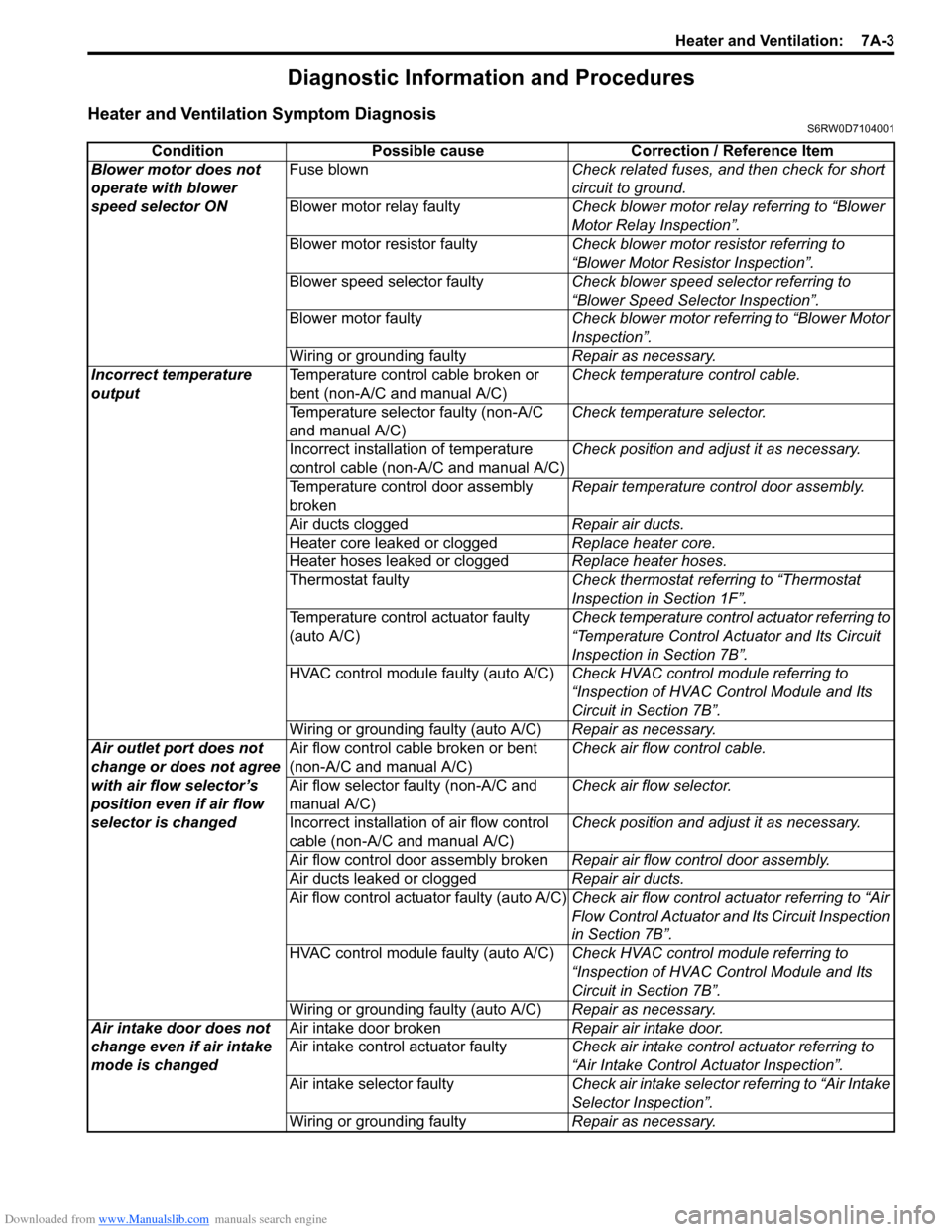
Condition Possible cause Correction / Reference Item
Blower motor does not
operate with blower
speed selector ONFuse blownCheck related fuses, and then check for short
circuit to ground.
Blower motor relay faultyCheck blower motor relay referring to “Blower
Motor Relay Inspection”.
Blower motor resistor faultyCheck blower motor resistor referring to
“Blower Motor Resistor Inspection”.
Blower speed selector faultyCheck blower speed selector referring to
“Blower Speed Selector Inspection”.
Blower motor faultyCheck blower motor referring to “Blower Motor
Inspection”.
Wiring or grounding faultyRepair as necessary.
Incorrect temperature
outputTemperature control cable broken or
bent (non-A/C and manual A/C)Check temperature control cable.
Temperature selector faulty (non-A/C
and manual A/C)Check temperature selector.
Incorrect installation of temperature
control cable (non-A/C and manual A/C)Check position and adjust it as necessary.
Temperature control door assembly
brokenRepair temperature control door assembly.
Air ducts cloggedRepair air ducts.
Heater core leaked or cloggedReplace heater core.
Heater hoses leaked or cloggedReplace heater hoses.
Thermostat faultyCheck thermostat referring to “Thermostat
Inspection in Section 1F”.
Temperature control actuator faulty
(auto A/C)Check temperature control actuator referring to
“Temperature Control Actuator and Its Circuit
Inspection in Section 7B”.
HVAC control module faulty (auto A/C)Check HVAC control module referring to
“Inspection of HVAC Control Module and Its
Circuit in Section 7B”.
Wiring or grounding faulty (auto A/C)Repair as necessary.
Air outlet port does not
change or does not agree
with air flow selector’s
position even if air flow
selector is changedAir flow control cable broken or bent
(non-A/C and manual A/C)Check air flow control cable.
Air flow selector faulty (non-A/C and
manual A/C)Check air flow selector.
Incorrect installation of air flow control
cable (non-A/C and manual A/C)Check position and adjust it as necessary.
Air flow control door assembly brokenRepair air flow control door assembly.
Air ducts leaked or cloggedRepair air ducts.
Air flow control actuator faulty (auto A/C)Check air flow control actuator referring to “Air
Flow Control Actuator and Its Circuit Inspection
in Section 7B”.
HVAC control module faulty (auto A/C)Check HVAC control module referring to
“Inspection of HVAC Control Module and Its
Circuit in Section 7B”.
Wiring or grounding faulty (auto A/C)Repair as necessary.
Air intake door does not
change even if air intake
mode is changedAir intake door brokenRepair air intake door.
Air intake control actuator faultyCheck air intake control actuator referring to
“Air Intake Control Actuator Inspection”.
Air intake selector faultyCheck air intake selector referring to “Air Intake
Selector Inspection”.
Wiring or grounding faultyRepair as necessary.
Page 1430 of 1556

Downloaded from www.Manualslib.com manuals search engine 9G-3 Seats:
Front Seat Removal and InstallationS6RW0D9706002
Removal
1) Disable air bag system referring to “Disabling Air
Bag System in Section 8B”.
2) Disconnect seat harness coupler and side air bag
coupler, if equipped.
3) Remove 4 mounting bolts to remove seat assembly.
4) Disassemble and repair seat as necessary.
Installation
Reverse removal procedure to install front seat.
• Torque to specifications as shown in “Front Seat
Components”.
• Enable air bag system referring to “Enabling Air Bag
System in Section 8B”.
Front Seat Heater Switch (Driver and Passenger
Side) Inspection (If Equipped)
S6RW0D9706005
1) Confirm that ignition switch is OFF position.
2) Remove console box.
3) Disconnect seat heater switch coupler and remove
seat heater switch.
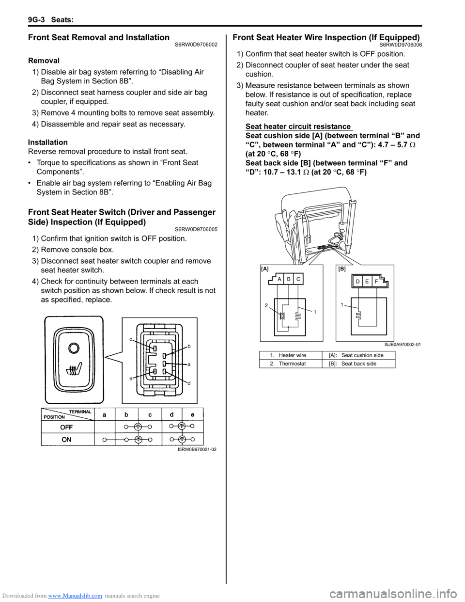
4) Check for continuity between terminals at each
switch position as shown below. If check result is not
as specified, replace.
Front Seat Heater Wire Inspection (If Equipped)S6RW0D9706006
1) Confirm that seat heater switch is OFF position.
2) Disconnect coupler of seat heater under the seat
cushion.
3) Measure resistance between terminals as shown
below. If resistance is out of specification, replace
faulty seat cushion and/or seat back including seat
heater.
Seat heater circuit resistance
Seat cushion side [A] (between terminal “B” and
“C”, between terminal “A” and “C”): 4.7 – 5.7 Ω
(at 20 °C, 68 °F)
Seat back side [B] (between terminal “F” and
“D”: 10.7 – 13.1 Ω (at 20 °C, 68 °F)
I5RW0B970001-02
1. Heater wire [A]: Seat cushion side
2. Thermostat [B]: Seat back side
ABCDE F [A] [B]
11
2
I5JB0A970002-01