width SUZUKI SX4 2006 1.G Service User Guide
[x] Cancel search | Manufacturer: SUZUKI, Model Year: 2006, Model line: SX4, Model: SUZUKI SX4 2006 1.GPages: 1556, PDF Size: 37.31 MB
Page 344 of 1556
Downloaded from www.Manualslib.com manuals search engine 1D-62 Engine Mechanical:
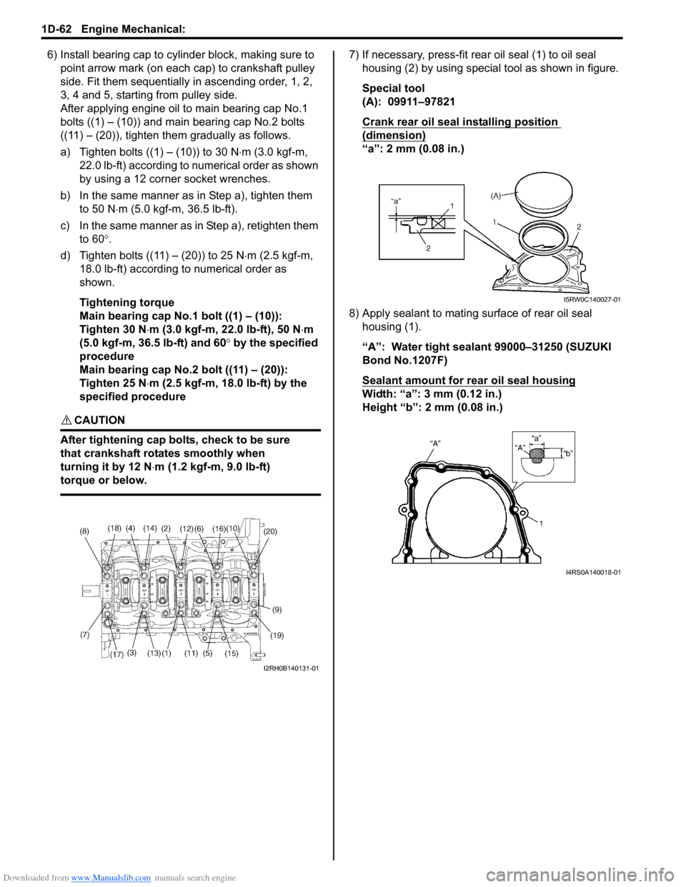
6) Install bearing cap to cylinder block, making sure to
point arrow mark (on each cap) to crankshaft pulley
side. Fit them sequentially in ascending order, 1, 2,
3, 4 and 5, starting from pulley side.
After applying engine oil to main bearing cap No.1
bolts ((1) – (10)) and main bearing cap No.2 bolts
((11) – (20)), tighten them gradually as follows.
a) Tighten bolts ((1) – (10)) to 30 N⋅m (3.0 kgf-m,
22.0 lb-ft) according to numerical order as shown
by using a 12 corner socket wrenches.
b) In the same manner as in Step a), tighten them
to 50 N⋅m (5.0 kgf-m, 36.5 lb-ft).
c) In the same manner as in Step a), retighten them
to 60°.
d) Tighten bolts ((11) – (20)) to 25 N⋅m (2.5 kgf-m,
18.0 lb-ft) according to numerical order as
shown.
Tightening torque
Main bearing cap No.1 bolt ((1) – (10)):
Tighten 30 N⋅m (3.0 kgf-m, 22.0 lb-ft), 50 N⋅m
(5.0 kgf-m, 36.5 lb-ft) and 60° by the specified
procedure
Main bearing cap No.2 bolt ((11) – (20)):
Tighten 25 N⋅m (2.5 kgf-m, 18.0 lb-ft) by the
specified procedure
CAUTION!
After tightening cap bolts, check to be sure
that crankshaft rotates smoothly when
turning it by 12 N⋅m (1.2 kgf-m, 9.0 lb-ft)
torque or below.
7) If necessary, press-fit rear oil seal (1) to oil seal
housing (2) by using special tool as shown in figure.
Special tool
(A): 09911–97821
Crank rear oil seal installing position
(dimension)
“a”: 2 mm (0.08 in.)
8) Apply sealant to mating surface of rear oil seal
housing (1).
“A”: Water tight sealant 99000–31250 (SUZUKI
Bond No.1207F)
Sealant amount for rear oil seal housing
Width: “a”: 3 mm (0.12 in.)
Height “b”: 2 mm (0.08 in.)
I2RH0B140131-01
I5RW0C140027-01
I4RS0A140018-01
Page 347 of 1556
Downloaded from www.Manualslib.com manuals search engine Engine Mechanical: 1D-65
Main Bearings InspectionS6RW0D1406040
General Information
• Service main bearings are available in standard size
and 0.25 mm (0.0098 in.) undersize, and each of them
has 5 kinds of bearings differing in tolerance.
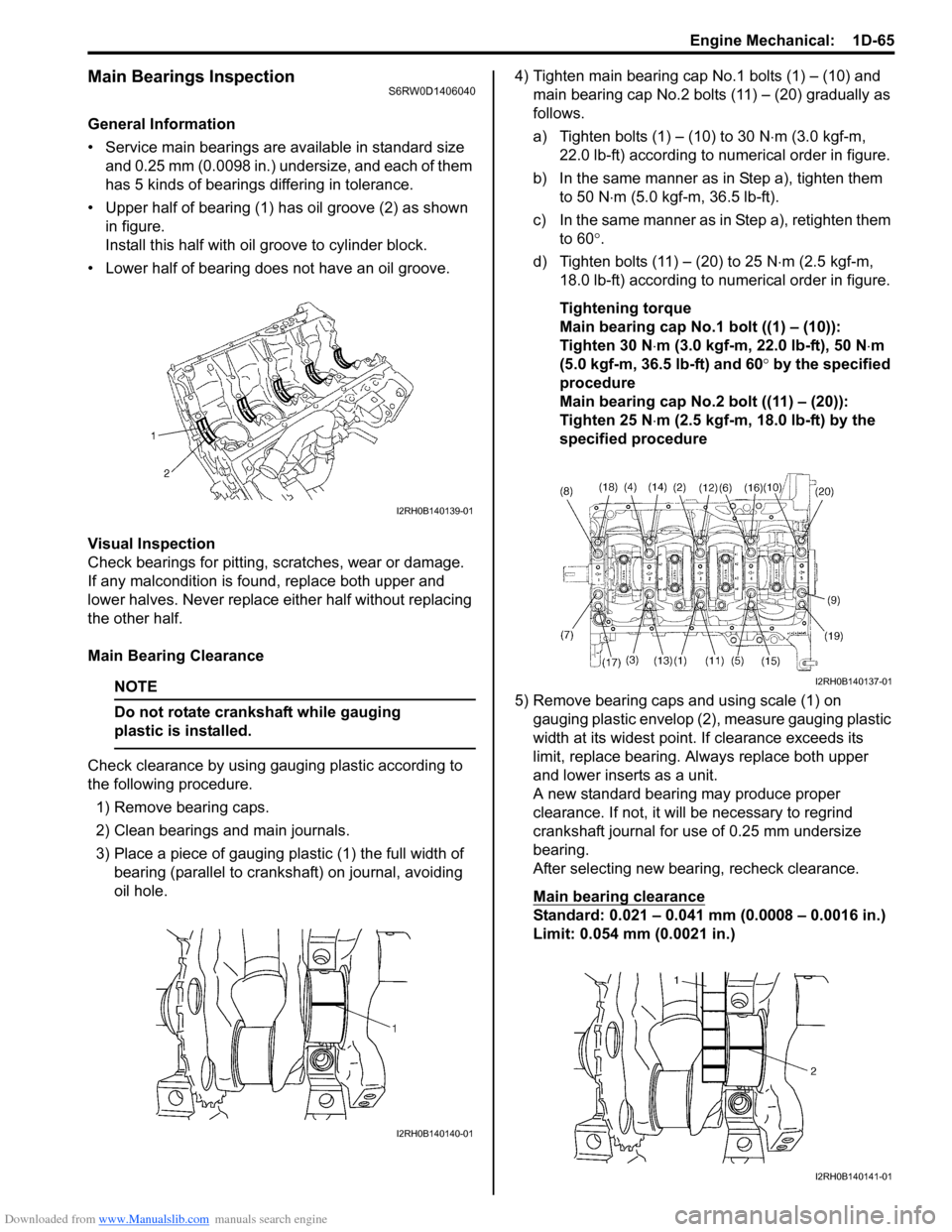
• Upper half of bearing (1) has oil groove (2) as shown
in figure.
Install this half with oil groove to cylinder block.
• Lower half of bearing does not have an oil groove.
Visual Inspection
Check bearings for pitting, scratches, wear or damage.
If any malcondition is found, replace both upper and
lower halves. Never replace either half without replacing
the other half.
Main Bearing Clearance
NOTE
Do not rotate crankshaft while gauging
plastic is installed.
Check clearance by using gauging plastic according to
the following procedure.
1) Remove bearing caps.
2) Clean bearings and main journals.
3) Place a piece of gauging plastic (1) the full width of
bearing (parallel to crankshaft) on journal, avoiding
oil hole.4) Tighten main bearing cap No.1 bolts (1) – (10) and
main bearing cap No.2 bolts (11) – (20) gradually as
follows.
a) Tighten bolts (1) – (10) to 30 N⋅m (3.0 kgf-m,
22.0 lb-ft) according to numerical order in figure.
b) In the same manner as in Step a), tighten them
to 50 N⋅m (5.0 kgf-m, 36.5 lb-ft).
c) In the same manner as in Step a), retighten them
to 60°.
d) Tighten bolts (11) – (20) to 25 N⋅m (2.5 kgf-m,
18.0 lb-ft) according to numerical order in figure.
Tightening torque
Main bearing cap No.1 bolt ((1) – (10)):
Tighten 30 N⋅m (3.0 kgf-m, 22.0 lb-ft), 50 N⋅m
(5.0 kgf-m, 36.5 lb-ft) and 60° by the specified
procedure
Main bearing cap No.2 bolt ((11) – (20)):
Tighten 25 N⋅m (2.5 kgf-m, 18.0 lb-ft) by the
specified procedure
5) Remove bearing caps and using scale (1) on
gauging plastic envelop (2), measure gauging plastic
width at its widest point. If clearance exceeds its
limit, replace bearing. Always replace both upper
and lower inserts as a unit.
A new standard bearing may produce proper
clearance. If not, it will be necessary to regrind
crankshaft journal for use of 0.25 mm undersize
bearing.
After selecting new bearing, recheck clearance.
Main bearing clearance
Standard: 0.021 – 0.041 mm (0.0008 – 0.0016 in.)
Limit: 0.054 mm (0.0021 in.)
I2RH0B140139-01
I2RH0B140140-01
I2RH0B140137-01
I2RH0B140141-01
Page 360 of 1556
Downloaded from www.Manualslib.com manuals search engine 1E-4 Engine Lubrication System:
Oil Pan and Oil Pump Strainer Removal and
Installation
S6RW0D1506002
Removal
1) Remove oil level gauge.
2) Drain engine oil by removing drain plug.
3) For 4WD model, dismount transfer referring to
“Transfer Dismounting and Remounting in Section
3C”.
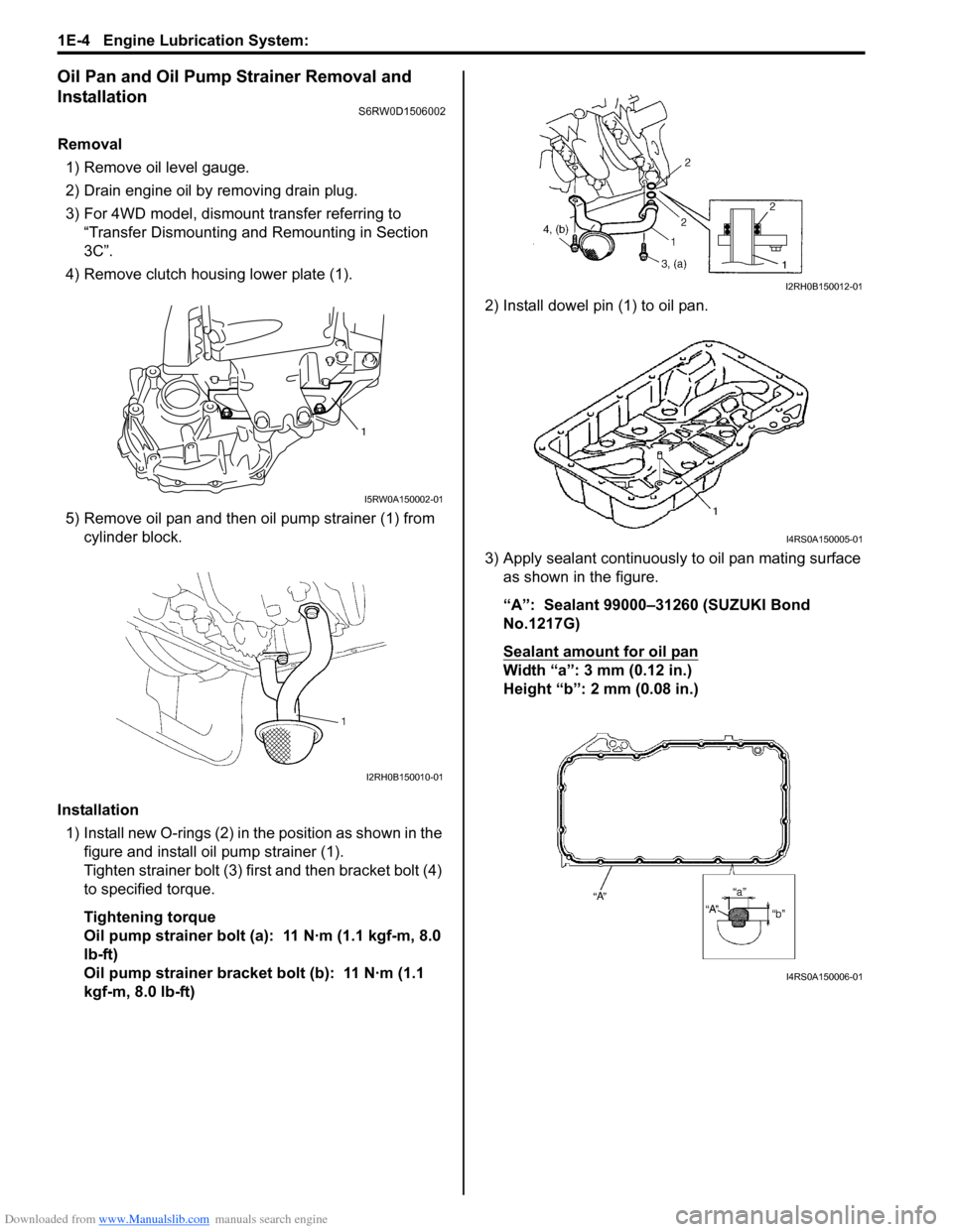
4) Remove clutch housing lower plate (1).
5) Remove oil pan and then oil pump strainer (1) from
cylinder block.
Installation
1) Install new O-rings (2) in the position as shown in the
figure and install oil pump strainer (1).
Tighten strainer bolt (3) first and then bracket bolt (4)
to specified torque.
Tightening torque
Oil pump strainer bolt (a): 11 N·m (1.1 kgf-m, 8.0
lb-ft)
Oil pump strainer bracket bolt (b): 11 N·m (1.1
kgf-m, 8.0 lb-ft)2) Install dowel pin (1) to oil pan.
3) Apply sealant continuously to oil pan mating surface
as shown in the figure.
“A”: Sealant 99000–31260 (SUZUKI Bond
No.1217G)
Sealant amount for oil pan
Width “a”: 3 mm (0.12 in.)
Height “b”: 2 mm (0.08 in.)
1
I5RW0A150002-01
I2RH0B150010-01
I2RH0B150012-01
I4RS0A150005-01
I4RS0A150006-01
Page 376 of 1556
Downloaded from www.Manualslib.com manuals search engine 1F-11 Engine Cooling System:
Installation
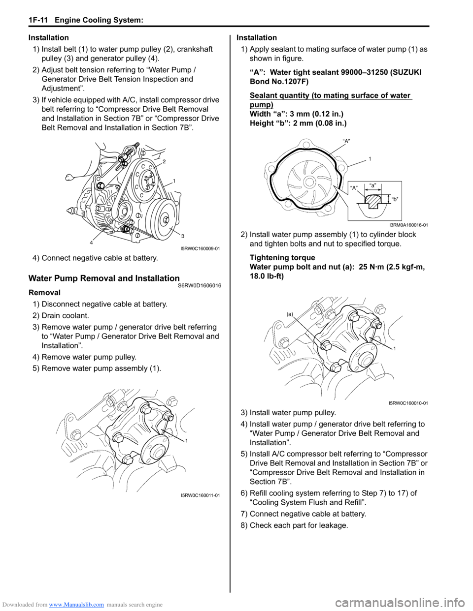
1) Install belt (1) to water pump pulley (2), crankshaft
pulley (3) and generator pulley (4).
2) Adjust belt tension referring to “Water Pump /
Generator Drive Belt Tension Inspection and
Adjustment”.
3) If vehicle equipped with A/C, install compressor drive
belt referring to “Compressor Drive Belt Removal
and Installation in Section 7B” or “Compressor Drive
Belt Removal and Installation in Section 7B”.
4) Connect negative cable at battery.
Water Pump Removal and InstallationS6RW0D1606016
Removal
1) Disconnect negative cable at battery.
2) Drain coolant.
3) Remove water pump / generator drive belt referring
to “Water Pump / Generator Drive Belt Removal and
Installation”.
4) Remove water pump pulley.
5) Remove water pump assembly (1).Installation
1) Apply sealant to mating surface of water pump (1) as
shown in figure.
“A”: Water tight sealant 99000–31250 (SUZUKI
Bond No.1207F)
Sealant quantity (to mating surface of water
pump)
Width “a”: 3 mm (0.12 in.)
Height “b”: 2 mm (0.08 in.)
2) Install water pump assembly (1) to cylinder block
and tighten bolts and nut to specified torque.
Tightening torque
Water pump bolt and nut (a): 25 N·m (2.5 kgf-m,
18.0 lb-ft)
3) Install water pump pulley.
4) Install water pump / generator drive belt referring to
“Water Pump / Generator Drive Belt Removal and
Installation”.
5) Install A/C compressor belt referring to “Compressor
Drive Belt Removal and Installation in Section 7B” or
“Compressor Drive Belt Removal and Installation in
Section 7B”.
6) Refill cooling system referring to Step 7) to 17) of
“Cooling System Flush and Refill”.
7) Connect negative cable at battery.
8) Check each part for leakage.
2
1
34I5RW0C160009-01
I5RW0C160011-01
I3RM0A160016-01
I5RW0C160010-01
Page 841 of 1556
Downloaded from www.Manualslib.com manuals search engine Manual Transmission/Transaxle: 5B-29
Reassembly
1) Clean all components thoroughly, inspect them for
any abnormality and replace with new ones as
necessary.
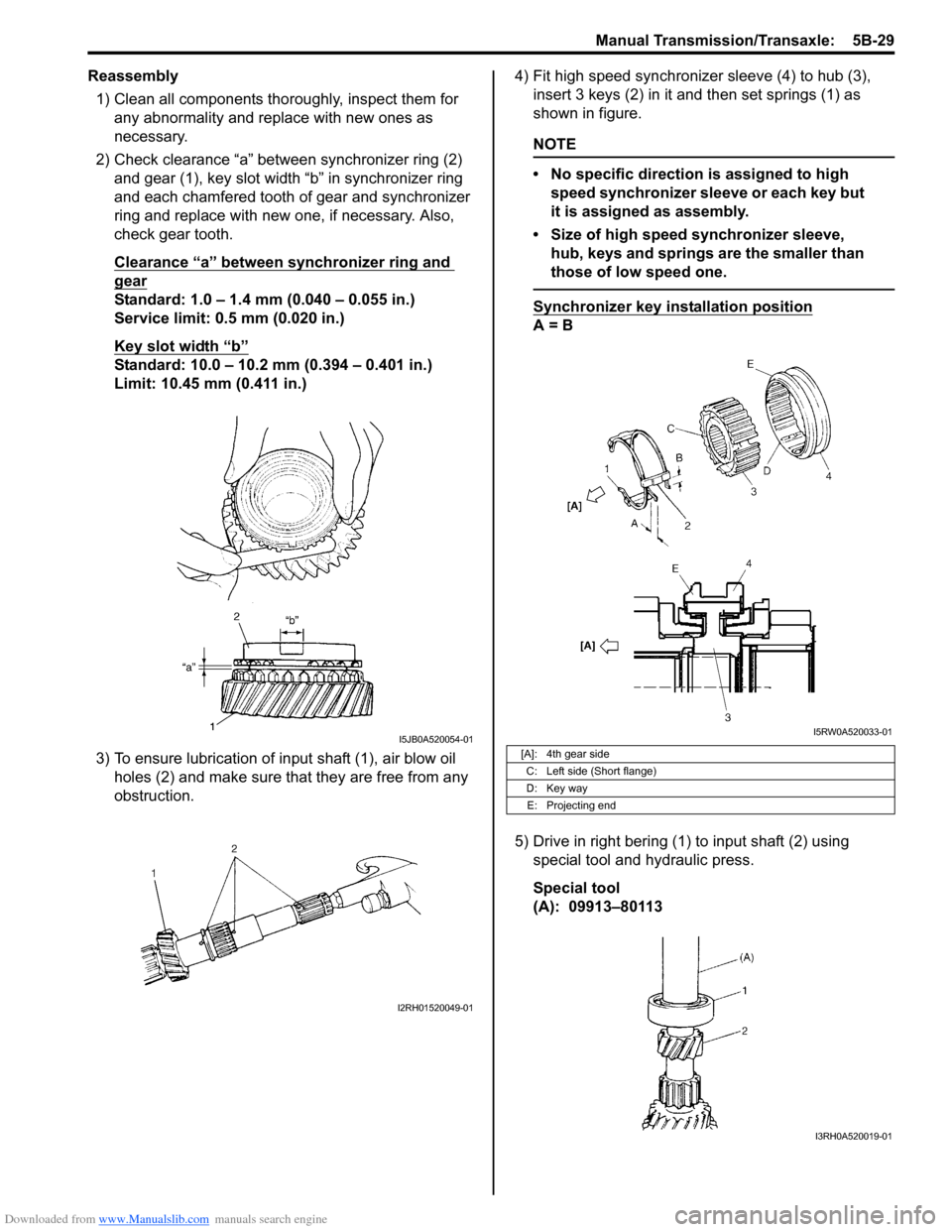
2) Check clearance “a” between synchronizer ring (2)
and gear (1), key slot width “b” in synchronizer ring
and each chamfered tooth of gear and synchronizer
ring and replace with new one, if necessary. Also,
check gear tooth.
Clearance “a” between synchronizer ring and
gear
Standard: 1.0 – 1.4 mm (0.040 – 0.055 in.)
Service limit: 0.5 mm (0.020 in.)
Key slot width “b”
Standard: 10.0 – 10.2 mm (0.394 – 0.401 in.)
Limit: 10.45 mm (0.411 in.)
3) To ensure lubrication of input shaft (1), air blow oil
holes (2) and make sure that they are free from any
obstruction.4) Fit high speed synchronizer sleeve (4) to hub (3),
insert 3 keys (2) in it and then set springs (1) as
shown in figure.
NOTE
• No specific direction is assigned to high
speed synchronizer sleeve or each key but
it is assigned as assembly.
• Size of high speed synchronizer sleeve,
hub, keys and springs are the smaller than
those of low speed one.
Synchronizer key installation position
A = B
5) Drive in right bering (1) to input shaft (2) using
special tool and hydraulic press.
Special tool
(A): 09913–80113
I5JB0A520054-01
I2RH01520049-01
[A]: 4th gear side
C: Left side (Short flange)
D: Key way
E: Projecting end
I5RW0A520033-01
I3RH0A520019-01
Page 844 of 1556
Downloaded from www.Manualslib.com manuals search engine 5B-32 Manual Transmission/Transaxle:
6) Disassemble synchronizer sleeve & hub assembly.
7) Take out 1st gear needle bearing from shaft.
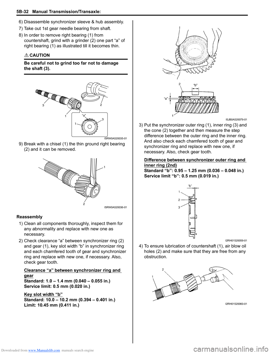
8) In order to remove right bearing (1) from
countershaft, grind with a grinder (2) one part “a” of
right bearing (1) as illustrated till it becomes thin.
CAUTION!
Be careful not to grind too far not to damage
the shaft (3).
9) Break with a chisel (1) the thin ground right bearing
(2) and it can be removed.
Reassembly
1) Clean all components thoroughly, inspect them for
any abnormality and replace with new one as
necessary.
2) Check clearance “a” between synchronizer ring (2)
and gear (1), key slot width “b” in synchronizer ring
and each chamfered tooth of gear and synchronizer
ring and replace with new one, if necessary. Also,
check gear tooth.
Clearance “a” between synchronizer ring and
gear
Standard: 1.0 – 1.4 mm (0.040 – 0.055 in.)
Service limit: 0.5 mm (0.020 in.)
Key slot width “b”
Standard: 10.0 – 10.2 mm (0.394 – 0.401 in.)
Limit: 10.45 mm (0.411 in.)3) Put the synchronizer outer ring (1), inner ring (3) and
the cone (2) together and then measure the step
difference between the outer ring and the inner ring.
And also check each chamfered tooth of gear and
synchronizer ring and replace with new one, if
necessary. Also, check gear tooth.
Difference between synchronizer outer ring and
inner ring (2nd)
Standard “b”: 0.95 – 1.25 mm (0.036 – 0.048 in.)
Service limit “b”: 0.5 mm (0.019 in.)
4) To ensure lubrication of countershaft (1), air blow oil
holes (2) and make sure that they are free from any
obstruction.
3
1
2
“a”31
I5RW0A520035-01
1
2I5RW0A520036-01
I5JB0A520079-01
I2RH01520059-01
I2RH01520060-01
Page 1393 of 1556
Downloaded from www.Manualslib.com manuals search engine Glass / Windows / Mirrors: 9E-8
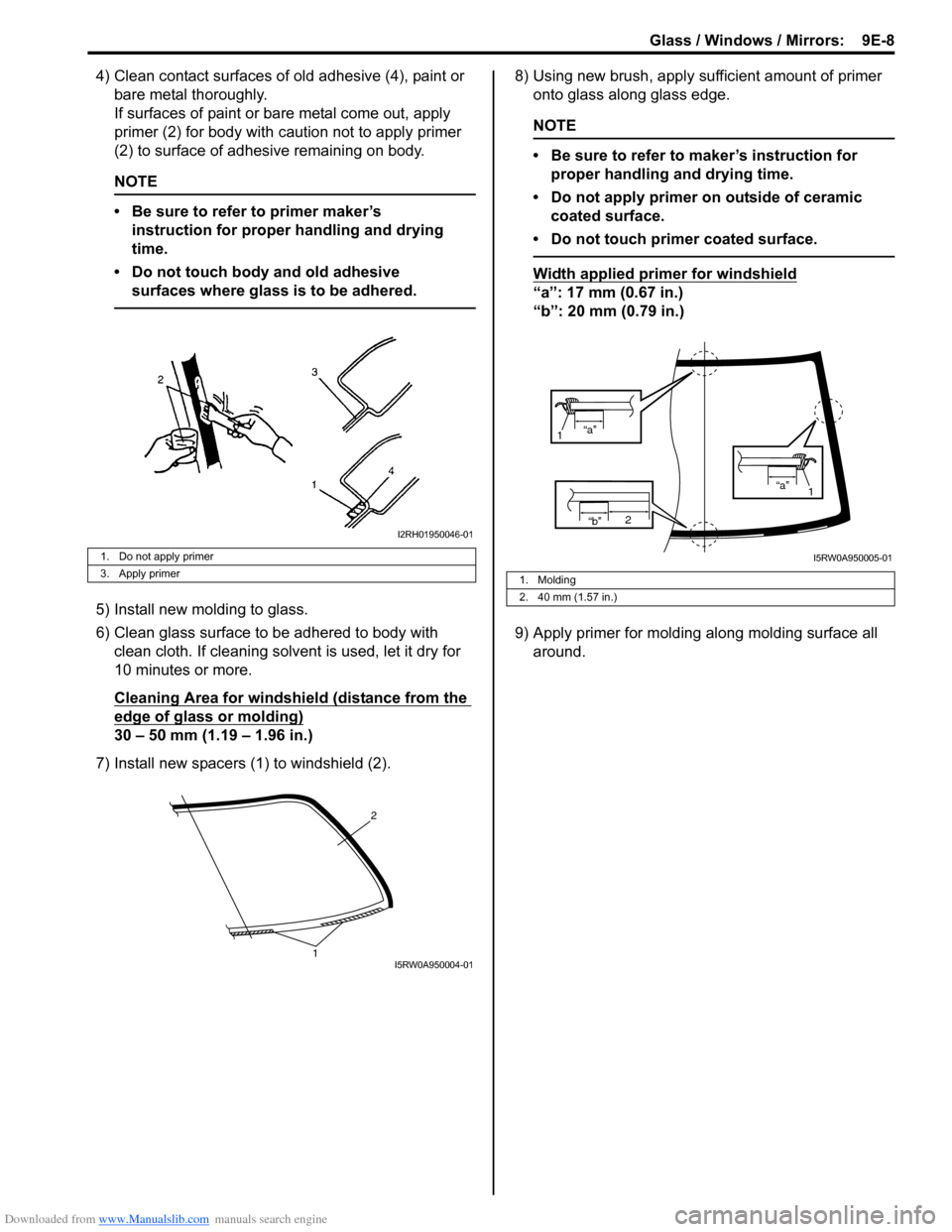
4) Clean contact surfaces of old adhesive (4), paint or
bare metal thoroughly.
If surfaces of paint or bare metal come out, apply
primer (2) for body with caution not to apply primer
(2) to surface of adhesive remaining on body.
NOTE
• Be sure to refer to primer maker’s
instruction for proper handling and drying
time.
• Do not touch body and old adhesive
surfaces where glass is to be adhered.
5) Install new molding to glass.
6) Clean glass surface to be adhered to body with
clean cloth. If cleaning solvent is used, let it dry for
10 minutes or more.
Cleaning Area for windshield (distance from the
edge of glass or molding)
30 – 50 mm (1.19 – 1.96 in.)
7) Install new spacers (1) to windshield (2).8) Using new brush, apply sufficient amount of primer
onto glass along glass edge.
NOTE
• Be sure to refer to maker’s instruction for
proper handling and drying time.
• Do not apply primer on outside of ceramic
coated surface.
• Do not touch primer coated surface.
Width applied primer for windshield
“a”: 17 mm (0.67 in.)
“b”: 20 mm (0.79 in.)
9) Apply primer for molding along molding surface all
around.
1. Do not apply primer
3. Apply primer
I2RH01950046-01
2
1I5RW0A950004-01
1. Molding
2. 40 mm (1.57 in.)
“b”2
“a”
1
“a”
1
I5RW0A950005-01
Page 1394 of 1556
Downloaded from www.Manualslib.com manuals search engine 9E-9 Glass / Windows / Mirrors:
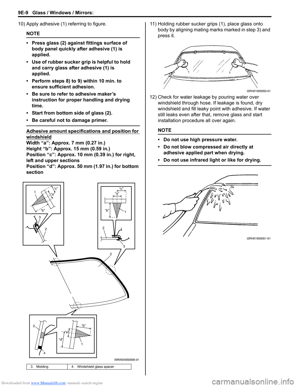
10) Apply adhesive (1) referring to figure.
NOTE
• Press glass (2) against fittings surface of
body panel quickly after adhesive (1) is
applied.
• Use of rubber sucker grip is helpful to hold
and carry glass after adhesive (1) is
applied.
• Perform steps 8) to 9) within 10 min. to
ensure sufficient adhesion.
• Be sure to refer to adhesive maker’s
instruction for proper handling and drying
time.
• Start from bottom side of glass (2).
• Be careful not to damage primer.
Adhesive amount specifications and position for
windshield
Width “a”: Approx. 7 mm (0.27 in.)
Height “b”: Approx. 15 mm (0.59 in.)
Position “c”: Approx. 10 mm (0.39 in.) for right,
left and upper sections
Position “d”: Approx. 50 mm (1.97 in.) for bottom
section11) Holding rubber sucker grips (1), place glass onto
body by aligning mating marks marked in step 3) and
press it.
12) Check for water leakage by pouring water over
windshield through hose. If leakage is found, dry
windshield and fill leaky point with adhesive. If water
still leaks even after that, remove glass and start
installation procedure all over again.
NOTE
• Do not use high pressure water.
• Do not blow compressed air directly at
adhesive applied part when drying.
• Do not use infrared light or like for drying.
3. Molding 4. Windshield glass spacer
2
“b”
“c”
2
3
1
“a”
3
2
1
“b”
“c”
“a”
2
4
1“b”
“d”
“a”
I5RW0A950006-01
I2RH01950050-01
I2RH01950051-01
Page 1395 of 1556
Downloaded from www.Manualslib.com manuals search engine Glass / Windows / Mirrors: 9E-10
CAUTION!
Upon completion of installation, note the
following.
• Sudden closing of door before adhesive is
completely set may cause glass to become
loose or to come off. Therefore, if door is
opened or closed before adhesive is
completely set, make sure to open all door
glasses and use proper care.
• If molding is not securely in place, hold it
down with a tape until adhesive is
completely set.
• Each adhesive has its own setting time.
• Be sure to refer to its maker’s instruction,
check setting time of adhesive to be used
and observe precautions to be taken
before adhesive is set.
• Refrain from driving till adhesive is
completely set so as to ensure proper and
sufficient adhesion.
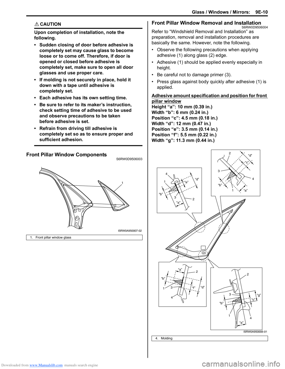
Front Pillar Window ComponentsS6RW0D9506003
Front Pillar Window Removal and InstallationS6RW0D9506004
Refer to “Windshield Removal and Installation” as
preparation, removal and installation procedures are
basically the same. However, note the following.
• Observe the following precautions when applying
adhesive (1) along glass (2) edge.
• Adhesive (1) should be applied evenly especially in
height.
• Be careful not to damage primer (3).
• Press glass against body quickly after adhesive (1) is
applied.
Adhesive amount specification and position for front
pillar window
Height “a”: 10 mm (0.39 in.)
Width “b”: 6 mm (0.24 in.)
Position “c”: 4.5 mm (0.18 in.)
Width “d”: 12 mm (0.47 in.)
Position “e”: 3.5 mm (0.14 in.)
Position “f”: 5.5 mm (0.22 in.)
Width “g”: 11.3 mm (0.44 in.)
1. Front pillar window glass
1
I5RW0A950007-02
4. Molding
“d”
“a” “b”“e”1
2 3
4
“d”
“a” “b”“c”
1 2
3
4
“d”
“f ” “a”
“b”12
3
4
“c”“g”
“a” “b”
12
3
4
I5RW0A950008-01
Page 1396 of 1556
Downloaded from www.Manualslib.com manuals search engine 9E-11 Glass / Windows / Mirrors:
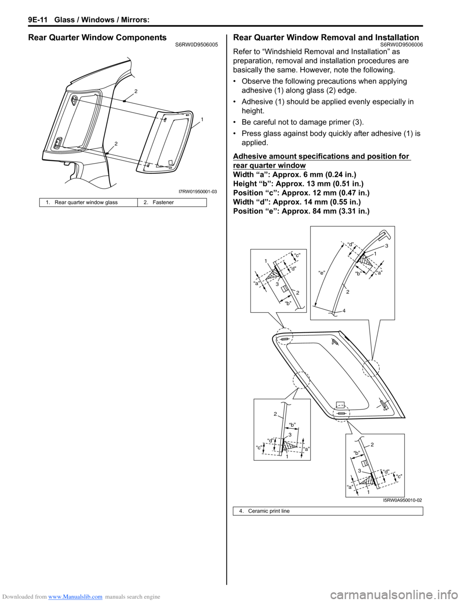
Rear Quarter Window ComponentsS6RW0D9506005Rear Quarter Window Removal and InstallationS6RW0D9506006
Refer to “Windshield Removal and Installation” as
preparation, removal and installation procedures are
basically the same. However, note the following.
• Observe the following precautions when applying
adhesive (1) along glass (2) edge.
• Adhesive (1) should be applied evenly especially in
height.
• Be careful not to damage primer (3).
• Press glass against body quickly after adhesive (1) is
applied.
Adhesive amount specifications and position for
rear quarter window
Width “a”: Approx. 6 mm (0.24 in.)
Height “b”: Approx. 13 mm (0.51 in.)
Position “c”: Approx. 12 mm (0.47 in.)
Width “d”: Approx. 14 mm (0.55 in.)
Position “e”: Approx. 84 mm (3.31 in.)
1. Rear quarter window glass 2. Fastener
2
2
1
I7RW01950001-03
4. Ceramic print line
“a”
“b”
“d”“c”“e”“a”
“b” “d”
“a” “b”
“d”
“c”
“a”“b”
“d”
“c”
1
3
2
3
1
2
4
2
3
1
2
3
1
I5RW0A950010-02