key battery SUZUKI SX4 2006 1.G Service Workshop Manual
[x] Cancel search | Manufacturer: SUZUKI, Model Year: 2006, Model line: SX4, Model: SUZUKI SX4 2006 1.GPages: 1556, PDF Size: 37.31 MB
Page 52 of 1556
Downloaded from www.Manualslib.com manuals search engine 1A-2 Engine General Information and Diagnosis:
• When checking ECM for DTC, keep in mind that DTC
is displayed on the scan tool as follows depending on
the scan tool used.
– SUZUKI scan tool displays DTC detected by ECM.
– CAN communication OBD generic scan tool
displays DTC detected by each of ECM and TCM
(for A/T model) simultaneously.
• Priorities for diagnosing troubles
If two or more DTCs are stored, proceed to the DTC
flow which has been detected earliest in the order and
follow the instruction in that flow.
If no instructions are given, troubleshoot DTCs
according to the following priorities.
a. DTCs other than DTC P0171 / P0172 (Fuel
system too lean / too rich), DTC P0300 / P0301 /
P0302 / P0303 / P0304 (Misfire detected) and
DTC P0401 / P0402 (EGR flow malfunction)
b. DTC P0171 / P0172 (Fuel system too lean / too
rich) and DTC P0401 / P0402 (EGR flow
malfunction)
c. DTC P0300 / P0301 / P0302 / P0303 / P0304
(Misfire detected)
• Be sure to read “Precautions for Electrical Circuit
Service in Section 00” before inspection and observe
what is written there.
• ECM replacement:
When substituting a known-good ECM, check for the
following conditions. Neglecting this check may cause
damage to a known-good ECM.
– Resistance value of all relays, actuators is as
specified respectively.
– MAP sensor, A/C refrigerant pressure sensor (if
equipped with A/C), accelerator pedal position
(APP) sensor and TP sensor are in good condition
and none of power circuits of these sensors is
shorted to ground.
• Communication of ECM, BCM, combination meter,
keyless start control module (if equipped with keyless
start control system), 4WD control module (if
equipped), TCM (for A/T model) and ABS control
module, is established by CAN (Controller Area
Network). (For more detail of CAN communication for
ECM, refer to “CAN Communication System
Description”). Therefore, handle CAN communication
line with care referring to “Precaution for CAN
Communication System in Section 00”.
• Immobilizer transponder code registration after
replacing ECM (Immobilizer model)
When ECM is replaced with new one or with another
one, make sure to register immobilizer transponder
code to ECM correctly according to “Procedure after
ECM Replacement in Section 10C”.Precautions for DTC TroubleshootingS6RW0D1100003
• Before performed trouble shooting, be sure to read
the “Precautions of ECM Circuit Inspection”.
• When measuring circuit voltage, resistance and/or
pulse signal at ECM connector, connect the special
tool to ECM and/or the ECM connectors referring to
“Inspection of ECM and Its Circuits”.
• Upon completion of inspection and repair work,
perform “DTC Confirmation Procedure” and confirm
that the trouble has been corrected.
Precautions of ECM Circuit InspectionS6RW0D1100004
• ECM connectors are waterproofed. Each terminal of
the ECM connectors is sealed up with the grommet.
Therefore, when measuring circuit voltage, resistance
and/or pulse signal at ECM connector, do not insert
the tester’s probe into the sealed terminal at the
harness side. When measuring circuit voltage,
resistance and/or pulse signal at ECM connector,
connect the special tool to the ECM connectors. And,
insert the tester’s probe into the special tool’s
connectors at the harness side, and then measure
voltage, resistance and/or pulse signal. Or, ECM and
its circuits may be damaged by water.
• Wire colors of the special tool’s connectors are
different from the ones of the ECM connectors.
However, the circuit arrangement of the special tool’s
connectors is same as the one of the ECM
connectors. Therefore, measure circuit voltage and
resistance by identifying the terminal location subject
to the measurement.
Precautions of Electric Throttle Body System
Calibration
S6RW0D1100005
After performing one of works described below, it is
necessary to re-register the completely closed throttle
valve reference position stored in memory of ECM. (For
detailed information, refer to “Description of Electric
Throttle Body System Calibration”.) For the procedure to
register such data in ECM, refer to “Electric Throttle
Body System Calibration in Section 1C”.
• To shut off backup power of ECM for such purposes of
battery replacement or “DOME” fuse removal
• To erase DTCs P0122, P0123, P0222, P0223, P2101,
P2102, P2103, P2111, P2112, P2119 and/or P2135
• To replace ECM
• To replace throttle body and/or accelerator pedal
position (APP) sensor assembly
Page 76 of 1556
Downloaded from www.Manualslib.com manuals search engine 1A-26 Engine General Information and Diagnosis:
• The MIL is turned on when the ECM and/or
TCM detect malfunction(s). Each ECM and
TCM stores diagnostic information as the
diagnostic trouble code (DTC) in its
memory and outputs the DTC to the scan
tool.
Therefore, check both of the ECM and TCM
for any DTC with the scan tool because the
DTC stored in ECM and TCM is not read
and displayed at a time. However, each of
the ECM and TCM needs not to be checked
with the generic scan tool because the
DTC stored in ECM and TCM is read and
displayed at a time.
1) Prepare CAN communication OBD generic scan tool
or SUZUKI scan tool.
Special tool
(A): SUZUKI scan tool (SUZUKI-SDT)
2) With ignition switch OFF, connect it to DLC (1)
located on underside of instrument panel at driver’s
seat side.
3) Turn ignition switch ON and confirm that MIL lights.
4) Read DTC and freeze frame data according to
instructions displayed on scan tool and print them or
write them down. Refer to scan tool operator’s
manual for details.
If communication between scan tool and ECM is not
possible, go to “Troubleshooting for Communication
Error with Scan Tool Using CAN”.
5) After completing the check, turn ignition switch off
and disconnect scan tool from DLC.
DTC ClearanceS6RW0D1104004
NOTE
There are two types of OBD system
depending on the vehicle specification.
For identification, refer to “Precaution on On-
Board Diagnostic (OBD) System”.
1) Connect SUZUKI scan tool or CAN communication
OBD generic scan tool to data link connector in the
same manner as when making this connection for
DTC check.2) Turn ignition switch OFF and then ON.
3) Erase DTC and pending DTC according to
instructions displayed on scan tool. Freeze frame
data is cleared with the DTC. Refer to scan tool
operator’s manual for further details.
If communication between scan tool and ECM is not
possible, go to “Troubleshooting for Communication
Error with Scan Tool Using CAN”.
4) After completing the clearance, turn ignition switch
OFF and disconnect scan tool from data link
connector.
NOTE
DTC and freeze frame data stored in ECM
memory are also cleared in the following
cases. Be careful not to clear them before
keeping their record.
• When power to ECM is cut off (by
disconnecting battery cable, removing
fuse or disconnecting ECM connectors).
• When the same malfunction (DTC) is not
detected again during 40 engine warm-up
cycles. (See “Warm-Up Cycle” of “On-
Board Diagnostic System Description”.)
Troubleshooting for Communication Error with
Scan Tool Using CAN
S6RW0D1104083
Perform this troubleshooting when it is not possible to
communicate between scan tool and ECM/TCM.
NOTE
• When performing this troubleshooting, be
sure to have full understanding of
“Precaution on CAN Troubleshooting” and
observe it.
• It may be possible that CAN system has
trouble because of fuse blown or low
battery voltage. Before troubleshooting,
check to make sure that fuse, battery
voltage and generator status are normal.
• When disconnecting each control module
connector in this troubleshooting, various
DTCs will be detected. Be sure to clear
DTCs in the following control modules
after completing this troubleshooting.
–ECM
–BCM
–TCM
– Keyless start control module
– 4WD control module
– HVAC control module (Auto A/C model)
– P/S control module
(A) 1I5RW0C110011-01
Page 93 of 1556
Downloaded from www.Manualslib.com manuals search engine Engine General Information and Diagnosis: 1A-43
THROTTLE MOTOR RELAY (ON/OFF)
ON: Throttle actuator (motor) control activated by ECM.
OF: Throttle actuator (motor) control stopped by ECM.
VEHICLE SPEED (km/h, mph)
It is computed based on pulse signals from front wheel
speed sensor (RH, LH) (for M/T model) or output shaft
speed sensor (VSS) (for A/T model).INJ PULSE WIDTH (FUEL INJECTION PULSE WIDTH,
msec.)
This parameter indicates time of the injector drive (valve
opening) pulse which is output from ECM (but injector
drive time of NO.1 cylinder for multiport fuel injection).
Visual InspectionS6RW0D1104008
Visually check the following parts and systems.
Engine Basic InspectionS6RW0D1104009
This check is very important for troubleshooting when ECM has detected no DTC and no abnormality has been found
in “Visual Inspection”.
Follow the flow carefully.Inspection item Reference section
• Engine oil – level, leakage “Engine Oil and Filter Change in Section 0B”
• Engine coolant – level, leakage “Coolant Level Check in Section 1F”
• Fuel – level, leakage“Fuel Lines and Connections Inspection in
Section 0B”
• Air cleaner element – dirt, clogging “Air Cleaner Filter Inspection in Section 0B”
• Battery – fluid level, corrosion of terminal“Battery Dismounting and Remounting in
Section 1J”
• Water pump belt – tension damage“Accessory Drive Belt Inspection in Section
0B”
• Throttle valve – operating sound“Electric Throttle Body Assembly On-Vehicle
Inspection in Section 1C”
• Vacuum hoses of air intake system – disconnection, looseness,
deterioration, bend“Vacuum Hose Inspection in Section 1B”
• Connectors of electric wire harness – disconnection, friction
• Fuses – burning
• Parts – installation, bolt – looseness
• Parts – deformation
• Other parts that can be checked visually
Also check the following items at engine start, if possible
• Malfunction indicator lamp – Operation “Malfunction Indicator Lamp (MIL) Check”
• Charge warning lamp – Operation “Generator Symptom Diagnosis in Section 1J”
• Engine oil pressure warning lamp – Operation “Oil Pressure Switch Inspection in Section 9C”
• Engine coolant temp. meter – Operation“Engine Coolant Temperature (ECT) Sensor
Inspection in Section 1C”
• Fuel level meter – Operation “Fuel Level Sensor Inspection in Section 9C”
• Tachometer – Operation
• Abnormal air being inhaled from air intake system
• Exhaust system – leakage of exhaust gas, noise
• Other parts that can be checked visually
Step Action Yes No
1Was “Engine and Emission Control System Check”
performed?Go to Step 2. Go to “Engine and
Emission Control
System Check”.
2Check battery voltage
Is it 11 V or more?Go to Step 3. Charge or replace
battery.
3Is vehicle equipped with keyless start control system?Go to Step 4. Go to Step 5.
Page 217 of 1556
Downloaded from www.Manualslib.com manuals search engine Engine General Information and Diagnosis: 1A-167
Troubleshooting for CAN-DTCS6RW0D1104084
Perform this troubleshooting when CAN-DTC is detected.
NOTE
• When performing this troubleshooting, be sure to have full understanding of “Precaution on CAN
Troubleshooting” and observe it.
• It may be possible that CAN system has trouble because of fuse blown or low battery voltage.
Before troubleshooting, check to make sure that fuse, battery voltage and generator status are
normal.
• When performing “Communication Bus Check” using SUZUKI scan tool (SUZUKI-SDT) in each step
of this troubleshooting, use the following table to determine whether the control module is in good
condition or not.
Also, while performing “Communication Bus Check”, do not perform any work other than instructed
in this troubleshooting. Or, it may occur that display of control module/sensor on SUZUKI-SDT
screen and/or its background color may change.
• When disconnecting each control module connector in this troubleshooting, various DTCs will be
detected. Be sure to clear DTCs in the following control modules after completing this
troubleshooting.
–ECM
– BCM
–TCM
– Keyless start control module
– 4WD control module
– HVAC control module (Auto A/C model)
– P/S control module
Wiring Diagram
Refer to “Troubleshooting for Communication Error with Scan Tool Using CAN”.
Trouble area
Refer to “Troubleshooting for Communication Error with Scan Tool Using CAN”. Judgment Display of Communication Bus Check
Normal• All connected control modules/sensors (communicated by CAN) are displayed and its back ground
color is “White”.
Abnormal• Even one of connected control modules/sensors (communicated by CAN) is not displayed.
• Display of even one of connected control modules/sensors (communicated by CAN) changes.
• Background color of even one of connected control modules/sensors (communicated by CAN) is
displayed in “Gray” or “Light green”.
• Background color of even one of connected control modules/sensors (communicated by CAN)
changes
Page 611 of 1556
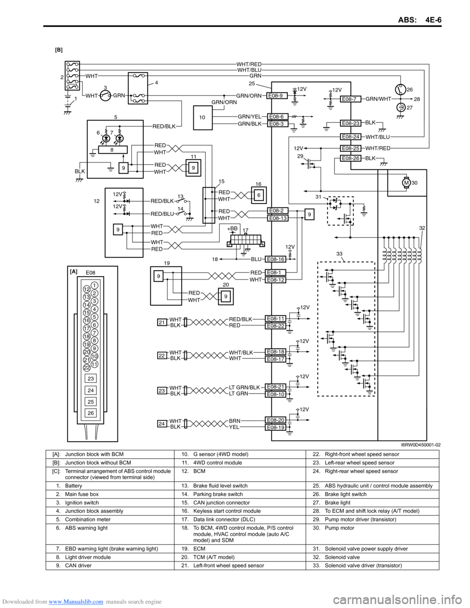
Downloaded from www.Manualslib.com manuals search engine ABS: 4E-6
17+BB
18BLU
WHT12VGRN/ORN 34
30E08-9
RED
WHT 1226
WHT/RED
12V
E08-7
19GRN
GRN
E08-16
12V
5
76
21REDRED/BLK
12V
BLKWHTE08-22 E08-11
23BLKWHTLT GRN/BLKLT GRN
12V
E08-10 E08-21
E08-23
E08-26
E08-1E08-12
24BLKWHT
12V
YELBRNE08-19 E08-20
27
1 2
RED/BLK
WHTRED
WHTRED
WHTRED9
E08-2E08-13WHT
E08-6
RED
9
9
11
9
9
9
REDWHT
WHTRED
12VE08-25
M
BLK
BLK
WHT/BLUWHT/RED
WHT/BLUE08-24
WHT
E08 [A]
1
2
3
4
5
6
7 12
13
14
15
16
17
18
19
20
21
228
9
10
11
23
24
25
26
GRN/WHT
22
12V
BLKWHTWHTWHT/BLKE08-17 E08-18
GRN/ORN28
2033
31
29
25
15
32
GRN/YELE08-3GRN/BLK
8
12V
12V
13
14RED/BLK
RED/BLU
WHTRED6
16
10
BLK [B]
I6RW0D450001-02
[A]: Junction block with BCM 10. G sensor (4WD model) 22. Right-front wheel speed sensor
[B]: Junction block without BCM 11. 4WD control module 23. Left-rear wheel speed sensor
[C]: Terminal arrangement of ABS control module
connector (viewed from terminal side)12. BCM 24. Right-rear wheel speed sensor
1. Battery 13. Brake fluid level switch 25. ABS hydraulic unit / control module assembly
2. Main fuse box 14. Parking brake switch 26. Brake light switch
3. Ignition switch 15. CAN junction connector 27. Brake light
4. Junction block assembly 16. Keyless start control module 28. To ECM and shift lock relay (A/T model)
5. Combination meter 17. Data link connector (DLC) 29. Pump motor driver (transistor)
6. ABS warning light 18. To BCM, 4WD control module, P/S control
module, HVAC control module (auto A/C
model) and SDM30. Pump motor
7. EBD warning light (brake warning light)19. ECM 31. Solenoid valve power supply driver
8. Light driver module 20. TCM (A/T model) 32. Solenoid valve
9. CAN driver 21. Left-front wheel speed sensor 33. Solenoid valve driver (transistor)
Page 649 of 1556
Downloaded from www.Manualslib.com manuals search engine Automatic Transmission/Transaxle: 5A-1
Transmission / Transaxle
Automatic Transmission/Transaxle
Precautions
Precautions in Diagnosing TroubleS6RW0D5100001
• Do not disconnect couplers from TCM, battery cable
from battery, TCM ground wire harness from engine or
main fuse before checking the diagnostic information
(DTC, freeze frame data, etc.) stored in TCM memory.
Such disconnection will clear memorized information
in TCM memory.
• Diagnostic information stored in TCM memory can be
cleared as well as checked by using SUZUKI scan
tool or CAN communication OBD generic scan tool.
Before using scan tool, read its Operator’s
(Instruction) Manual carefully to have good
understanding as to what functions are available and
how to use it.
It is indistinguishable which module turns on MIL
because not only ECM but also TCM turns on MIL.
Therefore, check both ECM and TCM for DTC when
MIL lights on.
When checking TCM for DTC, keep in mind that DTC
is displayed on the scan tool as follows depending on
the scan tool used.
– SUZUKI scan tool displays DTC detected by TCM.
– CAN communication OBD generic scan tool
displays DTC detected by each of ECM and TCM
simultaneously.
• Be sure to read “Precautions for Electrical Circuit
Service in Section 00” before inspection and observe
what is written there.
• TCM replacement
– When substituting a known-good TCM, check that
all relays and actuators have resistance of
specified value.
Neglecting this check may result in damage to good
TCM.
• Communication of ECM, BCM, combination meter,
keyless start control module (if equipped), ABS
control module, 4WD control module (if equipped),
TCM and DLC, is established by CAN (Controller
Area Network). (For more detail of CAN
communication for ECM, refer to “CAN
Communication System Description”). Therefore,
handle CAN communication line with care referring to
“Precaution for CAN Communication System in
Section 00”.
Precautions for Disassembly and ReassemblyS6RW0D5100002
When repairing automatic transaxle, it is necessary to
conduct the on-vehicle test to investigate where the
cause of the trouble lies first.
Then whether overhaul should be done or not is
determined. If the transaxle is disassembled without
such preliminary procedure, not only the cause of the
trouble would be unknown, but also a secondary trouble
may occur and often time would be wasted.
As the automatic transaxle consists of high precision
component, the following cautions should be strictly
observed when handling its parts in disassembly and
reassembly.
• Disassembling valve body assembly is prohibited
essentially. However, a few parts can be
disassembled. When disassembling valve body
component parts, confirm whether their parts are
allowed to disassemble or not referring to “Valve Body
Assembly Disassembly and Reassembly”.
• When component part of forward clutch, direct clutch,
2nd brake and/or O/D and 2nd coast brake, namely
clutch disc, brake disc, retaining plate and/or
separator plate, have been replaced, all learned
contents, which have been stored in TCM memory by
executing learning control, should be initialized
referring to “Learning Control Initialization”.
• Make sure to wash dirt off from the transaxle so that
no such dirt will enter the transaxle during
dismounting and remounting.
• Select a clean place free from dust and dirt for
overhauling.
• Place a rubber mat on the work bench to protect parts
from damage.
• Work gloves or shop cloth should not be used. (Use a
nylon cloth or a paper towel.)
• When separating the case joint, do not pry with a
screwdriver or such but tap with a plastic hammer
lightly.
• Make sure to wash dirt off from the transaxle so that
no such dirt will enter the transaxle during
disassembly and reassembly.
• Wash the disassembled parts in ATF (Automatic
Transaxle Fluid) or kerosene (using care not to allow
ATF or kerosene to get on your face, etc.) and confirm
that each fluid passage is not clogged by blowing air
into it. But use kerosene to wash the discs, resin
washers and rubber parts.
• Replace each gasket, oil seal and O-ring with a new
one.
• Apply ATF to sliding or rotating parts before
reassembly.
Page 735 of 1556

Downloaded from www.Manualslib.com manuals search engine Automatic Transmission/Transaxle: 5A-87
2) Remove adjuster (cable end) from select lever pin of
select lever assembly.
3) Remove adjuster (cable end) from select lever pin of
select lever assembly.
4) Release lock plate (1) which restrict moving of cable
end holder (2).
5) Push cable end holder (1) out from eye-end (2) using
an appropriate tool (3) to disengage cable.
6) Shift select lever to “N” position.
7) Apply grease to select lever pin and install adjuster
(cable end) to it.
: Grease 99000–25011 (SUZUKI Super Grease
A)
8) With both select lever and transmission range
sensor kept each “N” position, drive cable end holder
(1) in until it locks cable.
9) Slide lock plate (2) to secure cable end holder in
position.
10) After select cable was installed, check for the
following.
• Push vehicle with select lever shifted to “P” range.
Vehicle should not move.
• Vehicle can not be driven in “N” range.• Vehicle can be driven in “D”, “3”, “2” and “L”
ranges.
• Vehicle can be backed in “R” range.
Key Interlock Cable Removal and InstallationS6RW0D5106026
NOTE
Don’t bend interlock cable excessively when
removing and installing it, or system will not
operate correctly.
Removal
1) If the vehicle is equipped with air bag system,
disconnect negative cable at battery and disable air
bag system, referring to “Disabling Air Bag System in
Section 8B”.
2) Remove steering column cover.
3) Turn ignition switch to ACC position.
4) Pull out key interlock cable (1) from key cylinder
cover (2) while pressing checkhook with slotted
screwdriver (3) or the like.
5) Turn ignition switch to LOCK position.
6) Remove console box referring to “Console Box
Components in Section 9H”.
7) Detach cable end (1) from interlock cam (2) while
pressing claws (3) of interlock cam boss.
At this time, be careful not to cause damage to its
claws.
Detach cable casing cap (4) from bracket (5) while
pressing checkhook.
8) Remove interlock cable.
I2RH01510046-01
I2RH01510047-01
I3RM0B510037-01
2
13I5RW0C510045-01
4
5 3 12
4
I5RW0C510046-01
Page 737 of 1556

Downloaded from www.Manualslib.com manuals search engine Automatic Transmission/Transaxle: 5A-89
2) Turn ignition switch to ACC position.
3) Insert cable casing cap (1) into key cylinder cover (2)
securely.
4) Pull out lock button (1) of select lever side cable end
(2).
5) Shift select lever to “N” position.
NOTE
If select lever is in “P” position, shift select
lever referring to “Select Lever Inspection”.
6) Install cable casing cap (3) to bracket (4).
7) Connect cable end (1) to interlock cam (2) with
ignition switch turned to ACC position.
8) Drive lock button (5) in cable end until it locks cable
expansion and contraction.9) With select lever set at “P” position, turn ignition key
to ACC position and then check for the following
conditions.
• With knob button released, ignition key can be
turned from ACC position to LOCK position.
• With knob button pressed, ignition key cannot be
turned from ACC position to LOCK position.
10) Install knee protector to steering column.
11) Install steering column cover.
12) If the vehicle is equipped with air bag system,
connect negative cable at battery and enable air bag
system, referring to “Enabling Air Bag System in
Section 8B”.
Transmission Range Sensor Inspection and
Adjustment
S6RW0D5106009
1) Shift manual select lever (4) to “N” range.
2) Check that needle direction shaped on lock washer
(2) and “N” reference line (1) on transmission range
sensor are aligned. If not, loosen sensor bolts (3)
and align them.
Tightening torque
Transmission range sensor bolt (a): 5.5 N·m (
0.55 kgf-m, 4.0 lb-ft)
2
1I5RW0C510047-01
1 1
2
I2RH01510086-01
3
4 12
3 5
I5RW0C510048-01
1
3, (a) 4
2
I2RH0B510041-01
Page 877 of 1556
Downloaded from www.Manualslib.com manuals search engine Steering Wheel and Column: 6B-8
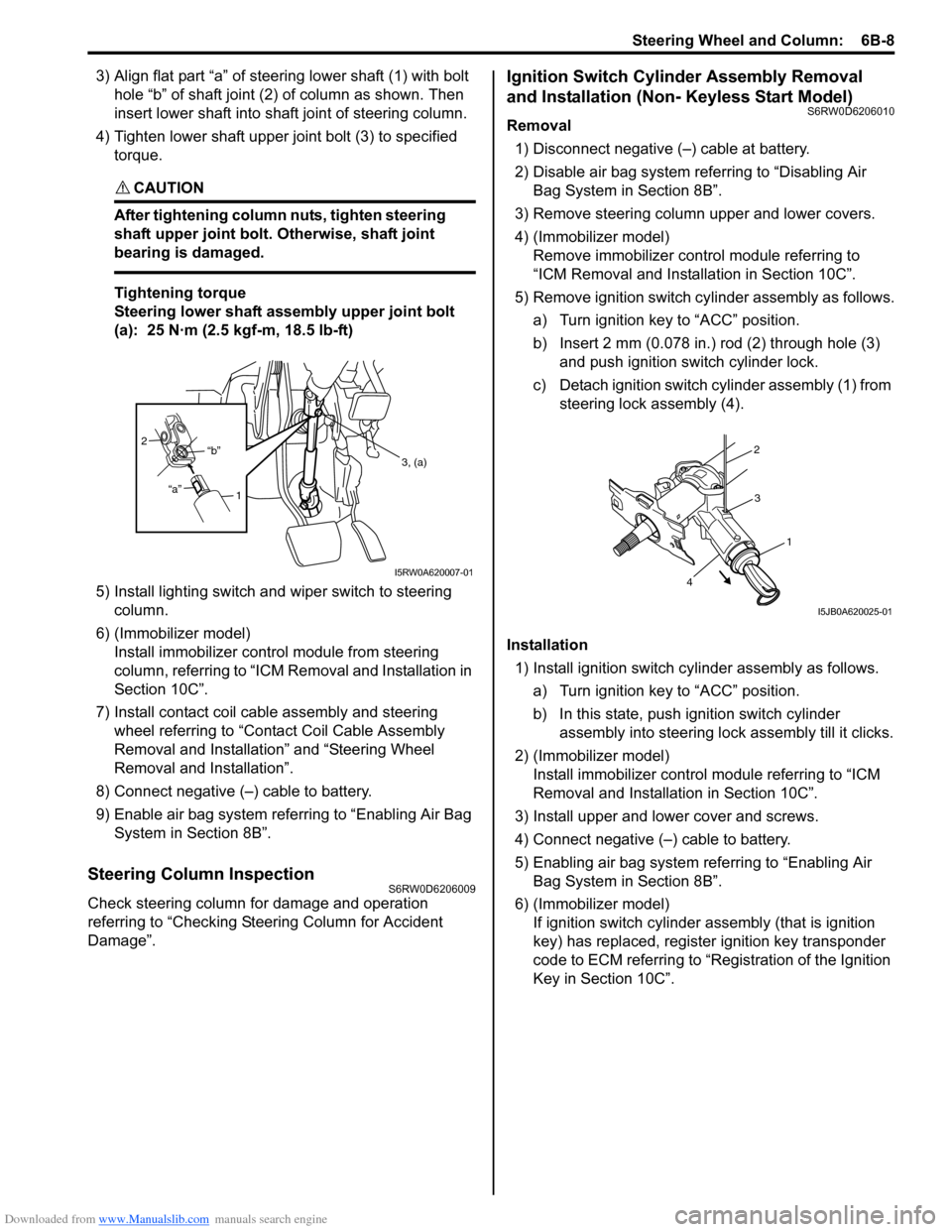
3) Align flat part “a” of steering lower shaft (1) with bolt
hole “b” of shaft joint (2) of column as shown. Then
insert lower shaft into shaft joint of steering column.
4) Tighten lower shaft upper joint bolt (3) to specified
torque.
CAUTION!
After tightening column nuts, tighten steering
shaft upper joint bolt. Otherwise, shaft joint
bearing is damaged.
Tightening torque
Steering lower shaft assembly upper joint bolt
(a): 25 N·m (2.5 kgf-m, 18.5 lb-ft)
5) Install lighting switch and wiper switch to steering
column.
6) (Immobilizer model)
Install immobilizer control module from steering
column, referring to “ICM Removal and Installation in
Section 10C”.
7) Install contact coil cable assembly and steering
wheel referring to “Contact Coil Cable Assembly
Removal and Installation” and “Steering Wheel
Removal and Installation”.
8) Connect negative (–) cable to battery.
9) Enable air bag system referring to “Enabling Air Bag
System in Section 8B”.
Steering Column InspectionS6RW0D6206009
Check steering column for damage and operation
referring to “Checking Steering Column for Accident
Damage”.
Ignition Switch Cylinder Assembly Removal
and Installation (Non- Keyless Start Model)
S6RW0D6206010
Removal
1) Disconnect negative (–) cable at battery.
2) Disable air bag system referring to “Disabling Air
Bag System in Section 8B”.
3) Remove steering column upper and lower covers.
4) (Immobilizer model)
Remove immobilizer control module referring to
“ICM Removal and Installation in Section 10C”.
5) Remove ignition switch cylinder assembly as follows.
a) Turn ignition key to “ACC” position.
b) Insert 2 mm (0.078 in.) rod (2) through hole (3)
and push ignition switch cylinder lock.
c) Detach ignition switch cylinder assembly (1) from
steering lock assembly (4).
Installation
1) Install ignition switch cylinder assembly as follows.
a) Turn ignition key to “ACC” position.
b) In this state, push ignition switch cylinder
assembly into steering lock assembly till it clicks.
2) (Immobilizer model)
Install immobilizer control module referring to “ICM
Removal and Installation in Section 10C”.
3) Install upper and lower cover and screws.
4) Connect negative (–) cable to battery.
5) Enabling air bag system referring to “Enabling Air
Bag System in Section 8B”.
6) (Immobilizer model)
If ignition switch cylinder assembly (that is ignition
key) has replaced, register ignition key transponder
code to ECM referring to “Registration of the Ignition
Key in Section 10C”.
1 2
“a”“b”
3, (a)
I5RW0A620007-01
2
3
1
4
I5JB0A620025-01
Page 1132 of 1556
Downloaded from www.Manualslib.com manuals search engine 8B-93 Air Bag System:
Repair Instructions
Disabling Air Bag SystemS6RW0D8206001
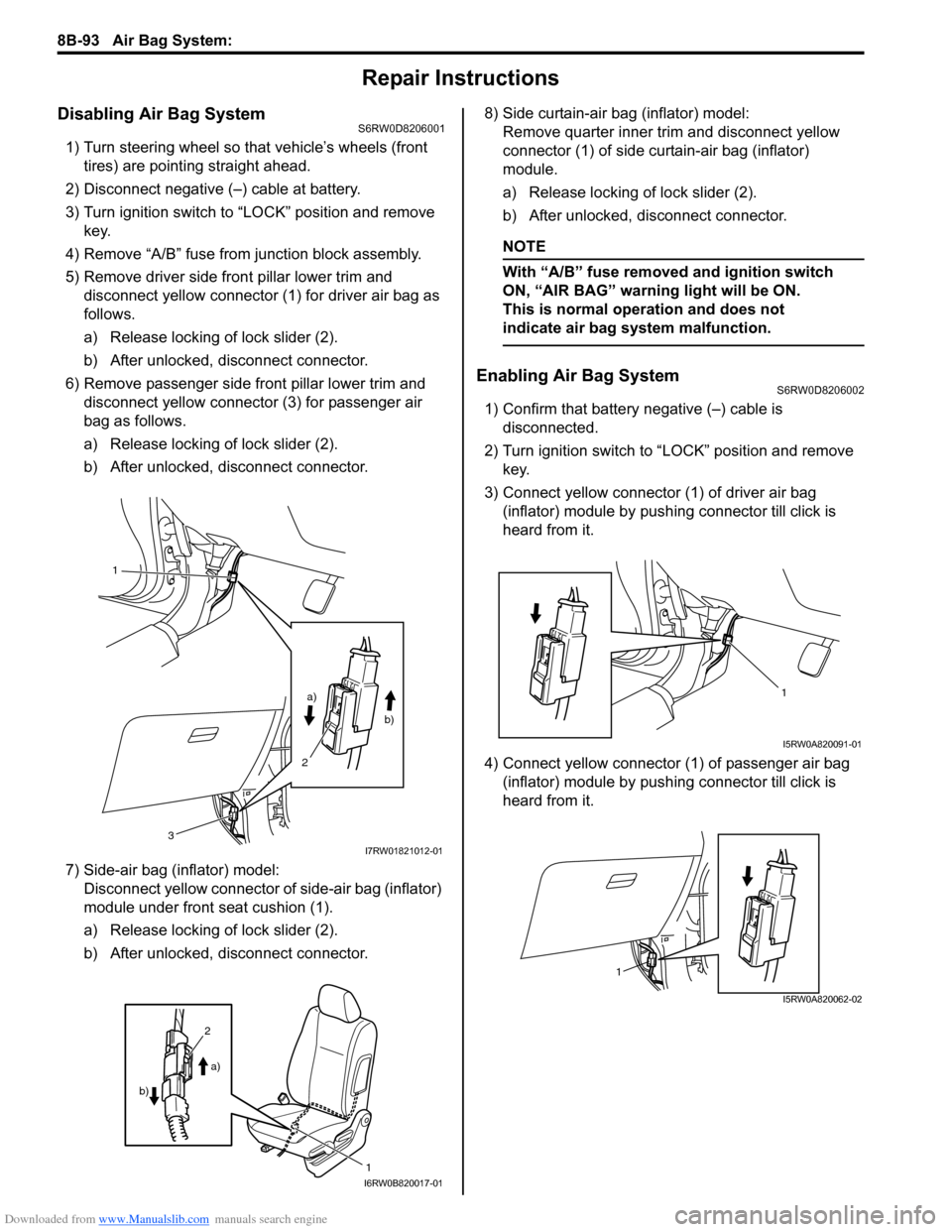
1) Turn steering wheel so that vehicle’s wheels (front
tires) are pointing straight ahead.
2) Disconnect negative (–) cable at battery.
3) Turn ignition switch to “LOCK” position and remove
key.
4) Remove “A/B” fuse from junction block assembly.
5) Remove driver side front pillar lower trim and
disconnect yellow connector (1) for driver air bag as
follows.
a) Release locking of lock slider (2).
b) After unlocked, disconnect connector.
6) Remove passenger side front pillar lower trim and
disconnect yellow connector (3) for passenger air
bag as follows.
a) Release locking of lock slider (2).
b) After unlocked, disconnect connector.
7) Side-air bag (inflator) model:
Disconnect yellow connector of side-air bag (inflator)
module under front seat cushion (1).
a) Release locking of lock slider (2).
b) After unlocked, disconnect connector.8) Side curtain-air bag (inflator) model:
Remove quarter inner trim and disconnect yellow
connector (1) of side curtain-air bag (inflator)
module.
a) Release locking of lock slider (2).
b) After unlocked, disconnect connector.
NOTE
With “A/B” fuse removed and ignition switch
ON, “AIR BAG” warning light will be ON.
This is normal operation and does not
indicate air bag system malfunction.
Enabling Air Bag SystemS6RW0D8206002
1) Confirm that battery negative (–) cable is
disconnected.
2) Turn ignition switch to “LOCK” position and remove
key.
3) Connect yellow connector (1) of driver air bag
(inflator) module by pushing connector till click is
heard from it.
4) Connect yellow connector (1) of passenger air bag
(inflator) module by pushing connector till click is
heard from it.
1
a)
b)
2
3
I7RW01821012-01
1
2
a)
b)
I6RW0B820017-01
1
I5RW0A820091-01
1
I5RW0A820062-02