Engine Mechanical SUZUKI SX4 2006 1.G Service Owner's Manual
[x] Cancel search | Manufacturer: SUZUKI, Model Year: 2006, Model line: SX4, Model: SUZUKI SX4 2006 1.GPages: 1556, PDF Size: 37.31 MB
Page 298 of 1556
![SUZUKI SX4 2006 1.G Service Owners Manual Downloaded from www.Manualslib.com manuals search engine 1D-16 Engine Mechanical:
Engine Mountings ComponentsS6RW0D1406012
I6RW0D140002-01
[A]: For 4WD model 4. Engine left mounting
: Be sure to dire SUZUKI SX4 2006 1.G Service Owners Manual Downloaded from www.Manualslib.com manuals search engine 1D-16 Engine Mechanical:
Engine Mountings ComponentsS6RW0D1406012
I6RW0D140002-01
[A]: For 4WD model 4. Engine left mounting
: Be sure to dire](/img/20/7612/w960_7612-297.png)
Downloaded from www.Manualslib.com manuals search engine 1D-16 Engine Mechanical:
Engine Mountings ComponentsS6RW0D1406012
I6RW0D140002-01
[A]: For 4WD model 4. Engine left mounting
: Be sure to direct paint mark to forward.12. Dynamic damper
[B]: For 2WD model 5. Engine rear mounting
: Be sure to direct paint mark to forward.13. Mounting member cushion
[C]: For M/T model 6. Engine rear mounting No.1 bracket 14. Yellow mark
[D]: For A/T model 7. Engine rear mounting No.2 bracket 15. Mounting member
Page 299 of 1556
Downloaded from www.Manualslib.com manuals search engine Engine Mechanical: 1D-17
Engine Assembly Removal and InstallationS6RW0D1406013
Removal
1) Relieve fuel pressure according to “Fuel Pressure
Relief Procedure in Section 1G”.
2) Disconnect negative and positive cable at battery.
3) Disconnect ECM connectors.
4) Remove battery and battery tray with ECM.
5) Remove right and left side engine under covers.
6) Remove A/C compressor belt by referring to
“Compressor Drive Belt Removal and Installation in
Section 7B” or “Compressor Drive Belt Removal and
Installation in Section 7B”.
7) Drain engine oil referring to “Engine Oil and Filter
Change in Section 0B”.
8) Drain transaxle oil referring to “Manual Transaxle Oil
Change in Section 5B” or “A/T Fluid Change in
Section 5A”.
9) Drain transfer oil referring to “Transfer Oil Change in
Section 3C”.
10) Drain coolant referring to “Cooling System Draining
in Section 1F”
11) Remove air cleaner assembly referring to “Air
Cleaner Assembly Removal and Installation”.
12) With hose connected, detach A/C compressor from
its bracket referring to “Compressor Assembly
Removal and Installation in Section 7B” or
“Compressor Assembly Removal and Installation in
Section 7B”.
CAUTION!
Suspend removed A/C compressor at a place
where no damage will be caused during
removal and installation of engine assembly.
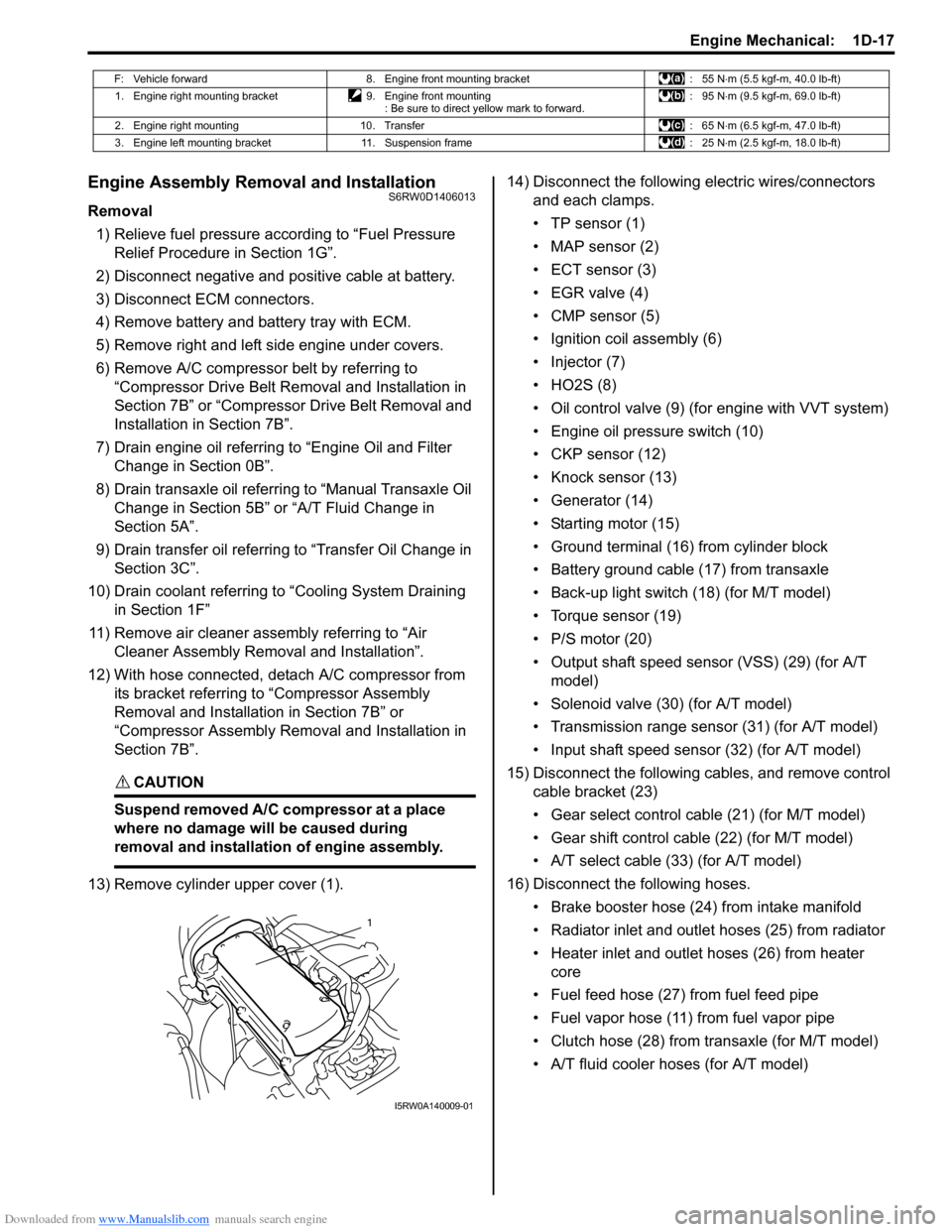
13) Remove cylinder upper cover (1).14) Disconnect the following electric wires/connectors
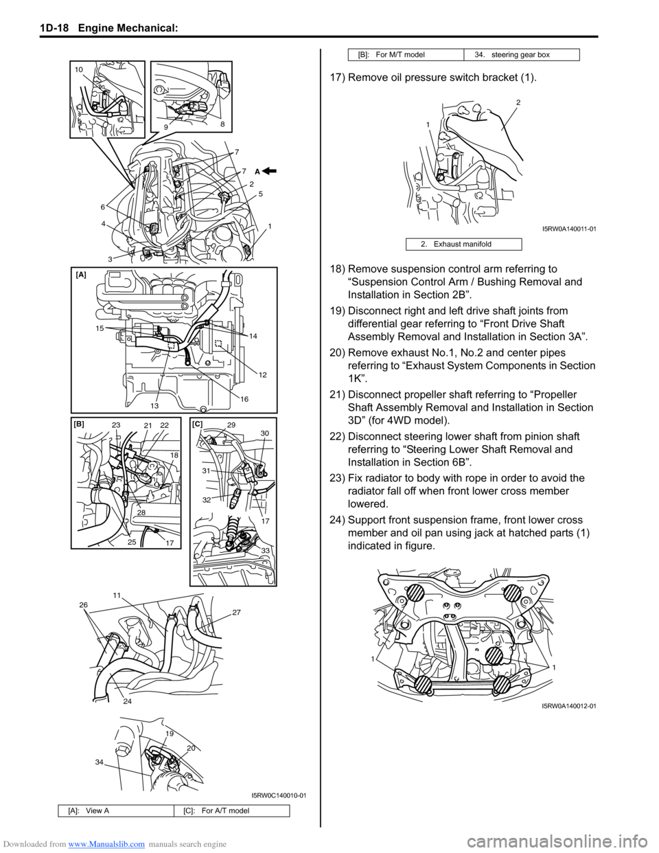
and each clamps.
• TP sensor (1)
• MAP sensor (2)
• ECT sensor (3)
•EGR valve (4)
• CMP sensor (5)
• Ignition coil assembly (6)
• Injector (7)
•HO2S (8)
• Oil control valve (9) (for engine with VVT system)
• Engine oil pressure switch (10)
• CKP sensor (12)
• Knock sensor (13)
• Generator (14)
• Starting motor (15)
• Ground terminal (16) from cylinder block
• Battery ground cable (17) from transaxle
• Back-up light switch (18) (for M/T model)
• Torque sensor (19)
• P/S motor (20)
• Output shaft speed sensor (VSS) (29) (for A/T
model)
• Solenoid valve (30) (for A/T model)
• Transmission range sensor (31) (for A/T model)
• Input shaft speed sensor (32) (for A/T model)
15) Disconnect the following cables, and remove control
cable bracket (23)
• Gear select control cable (21) (for M/T model)
• Gear shift control cable (22) (for M/T model)
• A/T select cable (33) (for A/T model)
16) Disconnect the following hoses.
• Brake booster hose (24) from intake manifold
• Radiator inlet and outlet hoses (25) from radiator
• Heater inlet and outlet hoses (26) from heater
core
• Fuel feed hose (27) from fuel feed pipe
• Fuel vapor hose (11) from fuel vapor pipe
• Clutch hose (28) from transaxle (for M/T model)
• A/T fluid cooler hoses (for A/T model)
F: Vehicle forward 8. Engine front mounting bracket : 55 N⋅m (5.5 kgf-m, 40.0 lb-ft)
1. Engine right mounting bracket 9. Engine front mounting
: Be sure to direct yellow mark to forward.: 95 N⋅m (9.5 kgf-m, 69.0 lb-ft)
2. Engine right mounting 10. Transfer : 65 N⋅m (6.5 kgf-m, 47.0 lb-ft)
3. Engine left mounting bracket 11. Suspension frame : 25 N⋅m (2.5 kgf-m, 18.0 lb-ft)
1
I5RW0A140009-01
Page 300 of 1556
Downloaded from www.Manualslib.com manuals search engine 1D-18 Engine Mechanical:
17) Remove oil pressure switch bracket (1).
18) Remove suspension control arm referring to
“Suspension Control Arm / Bushing Removal and
Installation in Section 2B”.
19) Disconnect right and left drive shaft joints from
differential gear referring to “Front Drive Shaft
Assembly Removal and Installation in Section 3A”.
20) Remove exhaust No.1, No.2 and center pipes
referring to “Exhaust System Components in Section
1K”.
21) Disconnect propeller shaft referring to “Propeller
Shaft Assembly Removal and Installation in Section
3D” (for 4WD model).
22) Disconnect steering lower shaft from pinion shaft
referring to “Steering Lower Shaft Removal and
Installation in Section 6B”.
23) Fix radiator to body with rope in order to avoid the
radiator fall off when front lower cross member
lowered.
24) Support front suspension frame, front lower cross
member and oil pan using jack at hatched parts (1)
indicated in figure.
[A]: View A [C]: For A/T model
6
3 45
1 7 7
2
8
9
10
A
15
14
16
20 19
26
24
27
12
13 [A]
11
34
232122
25
17 2818 [B] [C]
2930
31
32
17
33
I5RW0C140010-01
[B]: For M/T model 34. steering gear box
2. Exhaust manifold
1
2
I5RW0A140011-01
11
I5RW0A140012-01
Page 301 of 1556
Downloaded from www.Manualslib.com manuals search engine Engine Mechanical: 1D-19
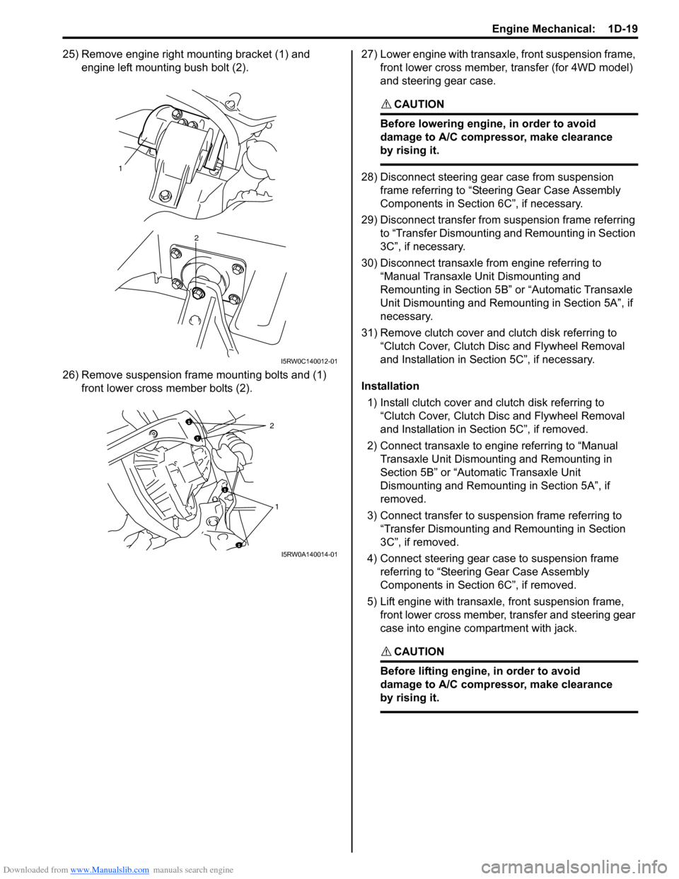
25) Remove engine right mounting bracket (1) and
engine left mounting bush bolt (2).
26) Remove suspension frame mounting bolts and (1)
front lower cross member bolts (2).27) Lower engine with transaxle, front suspension frame,
front lower cross member, transfer (for 4WD model)
and steering gear case.
CAUTION!
Before lowering engine, in order to avoid
damage to A/C compressor, make clearance
by rising it.
28) Disconnect steering gear case from suspension
frame referring to “Steering Gear Case Assembly
Components in Section 6C”, if necessary.
29) Disconnect transfer from suspension frame referring
to “Transfer Dismounting and Remounting in Section
3C”, if necessary.
30) Disconnect transaxle from engine referring to
“Manual Transaxle Unit Dismounting and
Remounting in Section 5B” or “Automatic Transaxle
Unit Dismounting and Remounting in Section 5A”, if
necessary.
31) Remove clutch cover and clutch disk referring to
“Clutch Cover, Clutch Disc and Flywheel Removal
and Installation in Section 5C”, if necessary.
Installation
1) Install clutch cover and clutch disk referring to
“Clutch Cover, Clutch Disc and Flywheel Removal
and Installation in Section 5C”, if removed.
2) Connect transaxle to engine referring to “Manual
Transaxle Unit Dismounting and Remounting in
Section 5B” or “Automatic Transaxle Unit
Dismounting and Remounting in Section 5A”, if
removed.
3) Connect transfer to suspension frame referring to
“Transfer Dismounting and Remounting in Section
3C”, if removed.
4) Connect steering gear case to suspension frame
referring to “Steering Gear Case Assembly
Components in Section 6C”, if removed.
5) Lift engine with transaxle, front suspension frame,
front lower cross member, transfer and steering gear
case into engine compartment with jack.
CAUTION!
Before lifting engine, in order to avoid
damage to A/C compressor, make clearance
by rising it.
1
2
I5RW0C140012-01
2
1
I5RW0A140014-01
Page 302 of 1556
Downloaded from www.Manualslib.com manuals search engine 1D-20 Engine Mechanical:
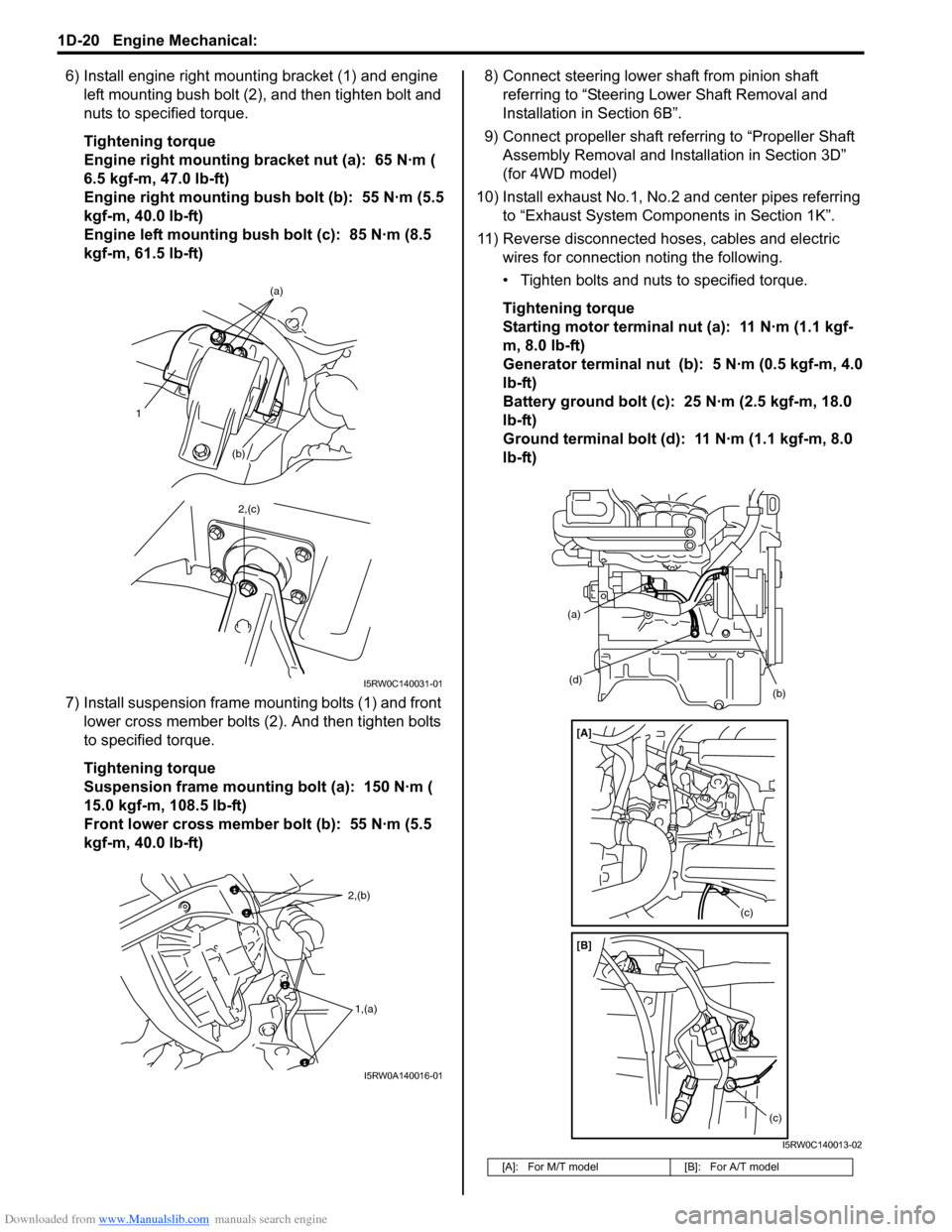
6) Install engine right mounting bracket (1) and engine
left mounting bush bolt (2), and then tighten bolt and
nuts to specified torque.
Tightening torque
Engine right mounting bracket nut (a): 65 N·m (
6.5 kgf-m, 47.0 lb-ft)
Engine right mounting bush bolt (b): 55 N·m (5.5
kgf-m, 40.0 lb-ft)
Engine left mounting bush bolt (c): 85 N·m (8.5
kgf-m, 61.5 lb-ft)
7) Install suspension frame mounting bolts (1) and front
lower cross member bolts (2). And then tighten bolts
to specified torque.
Tightening torque
Suspension frame mounting bolt (a): 150 N·m (
15.0 kgf-m, 108.5 lb-ft)
Front lower cross member bolt (b): 55 N·m (5.5
kgf-m, 40.0 lb-ft)8) Connect steering lower shaft from pinion shaft
referring to “Steering Lower Shaft Removal and
Installation in Section 6B”.
9) Connect propeller shaft referring to “Propeller Shaft
Assembly Removal and Installation in Section 3D”
(for 4WD model)
10) Install exhaust No.1, No.2 and center pipes referring
to “Exhaust System Components in Section 1K”.
11) Reverse disconnected hoses, cables and electric
wires for connection noting the following.
• Tighten bolts and nuts to specified torque.
Tightening torque
Starting motor terminal nut (a): 11 N·m (1.1 kgf-
m, 8.0 lb-ft)
Generator terminal nut (b): 5 N·m (0.5 kgf-m, 4.0
lb-ft)
Battery ground bolt (c): 25 N·m (2.5 kgf-m, 18.0
lb-ft)
Ground terminal bolt (d): 11 N·m (1.1 kgf-m, 8.0
lb-ft)
1
(b)(a)
2,(c)
I5RW0C140031-01
2,(b)
1,(a)
I5RW0A140016-01
[A]: For M/T model [B]: For A/T model
(d)
(a)
(b)
(c)
(c)
[A]
[B]
I5RW0C140013-02
Page 303 of 1556
Downloaded from www.Manualslib.com manuals search engine Engine Mechanical: 1D-21
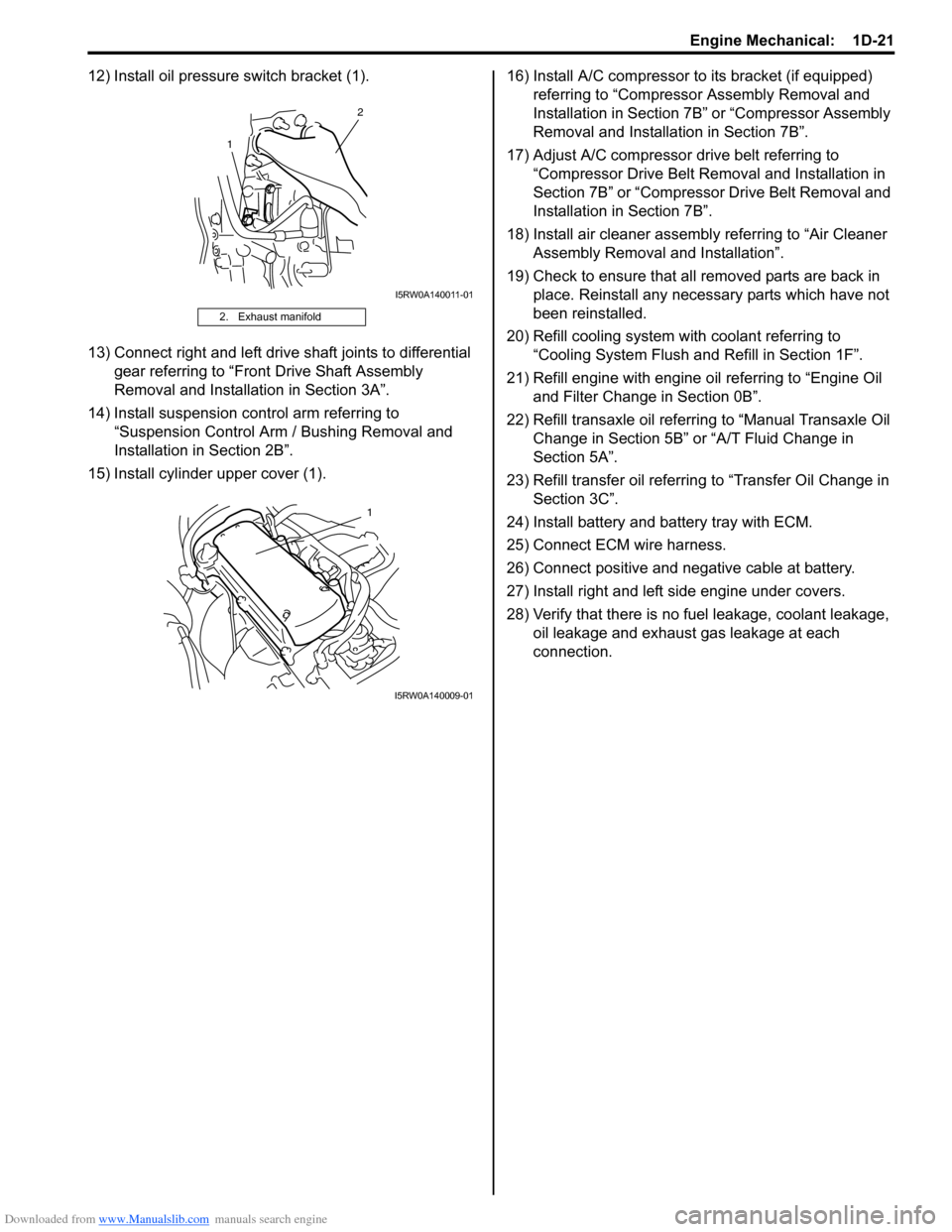
12) Install oil pressure switch bracket (1).
13) Connect right and left drive shaft joints to differential
gear referring to “Front Drive Shaft Assembly
Removal and Installation in Section 3A”.
14) Install suspension control arm referring to
“Suspension Control Arm / Bushing Removal and
Installation in Section 2B”.
15) Install cylinder upper cover (1).16) Install A/C compressor to its bracket (if equipped)
referring to “Compressor Assembly Removal and
Installation in Section 7B” or “Compressor Assembly
Removal and Installation in Section 7B”.
17) Adjust A/C compressor drive belt referring to
“Compressor Drive Belt Removal and Installation in
Section 7B” or “Compressor Drive Belt Removal and
Installation in Section 7B”.
18) Install air cleaner assembly referring to “Air Cleaner
Assembly Removal and Installation”.
19) Check to ensure that all removed parts are back in
place. Reinstall any necessary parts which have not
been reinstalled.
20) Refill cooling system with coolant referring to
“Cooling System Flush and Refill in Section 1F”.
21) Refill engine with engine oil referring to “Engine Oil
and Filter Change in Section 0B”.
22) Refill transaxle oil referring to “Manual Transaxle Oil
Change in Section 5B” or “A/T Fluid Change in
Section 5A”.
23) Refill transfer oil referring to “Transfer Oil Change in
Section 3C”.
24) Install battery and battery tray with ECM.
25) Connect ECM wire harness.
26) Connect positive and negative cable at battery.
27) Install right and left side engine under covers.
28) Verify that there is no fuel leakage, coolant leakage,
oil leakage and exhaust gas leakage at each
connection.
2. Exhaust manifold
1
2
I5RW0A140011-01
1
I5RW0A140009-01
Page 304 of 1556
![SUZUKI SX4 2006 1.G Service Owners Manual Downloaded from www.Manualslib.com manuals search engine 1D-22 Engine Mechanical:
Timing Chain Cover ComponentsS6RW0D1406014
I5RW0C140041-01
[A]: For engine with VVT 8. Timing chain cover mounting
n SUZUKI SX4 2006 1.G Service Owners Manual Downloaded from www.Manualslib.com manuals search engine 1D-22 Engine Mechanical:
Timing Chain Cover ComponentsS6RW0D1406014
I5RW0C140041-01
[A]: For engine with VVT 8. Timing chain cover mounting
n](/img/20/7612/w960_7612-303.png)
Downloaded from www.Manualslib.com manuals search engine 1D-22 Engine Mechanical:
Timing Chain Cover ComponentsS6RW0D1406014
I5RW0C140041-01
[A]: For engine with VVT 8. Timing chain cover mounting
nut17. Oil control valve
[B]: For engine without VVT 9. Oil gallery pipe No.1 18. Oil control valve mounting nut
1. Crankshaft pulley bolt 10. Copper washer 19. Cap
2. Crankshaft pulley 11. Oil gallery pipe No.1 bolt : 11 N⋅m (1.1 kgf-m, 8.0 lb-ft)
3. Oil seal
: Apply engine oil to oil seal lip.12. Oil gallery pipe No.2 : 25 N⋅m (2.5 kgf-m, 18.0 lb-ft)
4. Timing chain cover
: Apply sealant 99000-31140 to the mating
surface of cylinder and cylinder head.
: Apply sealant 99000-31260 to the mating
surface of timing chain cover referring to the
figure of Step 4) of “Installation” under “Timing
Chain Cover Removal and Installation”.13. Oil gallery pipe No.2 bolt : 30 N⋅m (3.0 kgf-m, 22.0 lb-ft)
5. Pin 14. Oil gallery pipe No.3 : 150 N⋅m (15.0 kgf-m, 108.5 lb-ft)
6. Cap bolt 15. Oil gallery pipe No.3 bolt : Do not reuse.
7. Timing chain cover mounting bolts 16. O-ring
: Apply engine oil.
Page 305 of 1556
Downloaded from www.Manualslib.com manuals search engine Engine Mechanical: 1D-23
Timing Chain Cover Removal and InstallationS6RW0D1406015
CAUTION!
• Keep working table, tools and hands clean
while overhauling.
• Use special care to handle aluminum parts
so as not to damage them.
• Do not expose removed parts to dust.
Keep them always clean.
Removal
1) Remove engine assembly from vehicle referring to
“Engine Assembly Removal and Installation”.
2) Remove water pump / generator drive belt referring
to “Water Pump / Generator Drive Belt Removal and
Installation in Section 1F”.
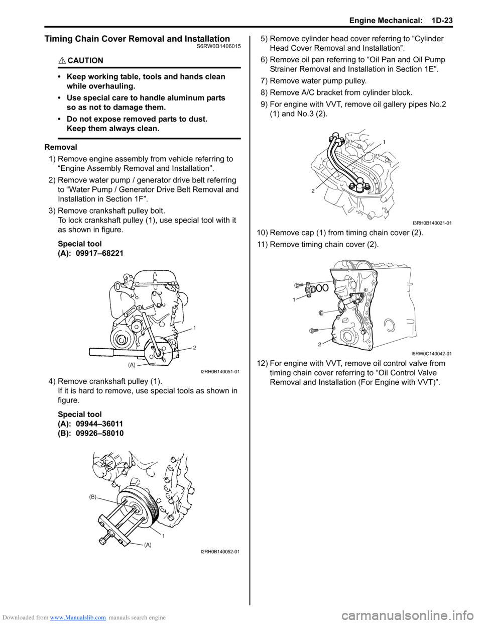
3) Remove crankshaft pulley bolt.
To lock crankshaft pulley (1), use special tool with it
as shown in figure.
Special tool
(A): 09917–68221
4) Remove crankshaft pulley (1).
If it is hard to remove, use special tools as shown in
figure.
Special tool
(A): 09944–36011
(B): 09926–580105) Remove cylinder head cover referring to “Cylinder
Head Cover Removal and Installation”.
6) Remove oil pan referring to “Oil Pan and Oil Pump
Strainer Removal and Installation in Section 1E”.
7) Remove water pump pulley.
8) Remove A/C bracket from cylinder block.
9) For engine with VVT, remove oil gallery pipes No.2
(1) and No.3 (2).
10) Remove cap (1) from timing chain cover (2).
11) Remove timing chain cover (2).
12) For engine with VVT, remove oil control valve from
timing chain cover referring to “Oil Control Valve
Removal and Installation (For Engine with VVT)”.
I2RH0B140051-01
I2RH0B140052-01
1
2
I3RH0B140021-01
1
2
I5RW0C140042-01
Page 306 of 1556
Downloaded from www.Manualslib.com manuals search engine 1D-24 Engine Mechanical:
Installation
1) Clean sealing surface on timing chain cover, cylinder
block and cylinder head.
Remove oil, old sealant and dust from sealing
surface.
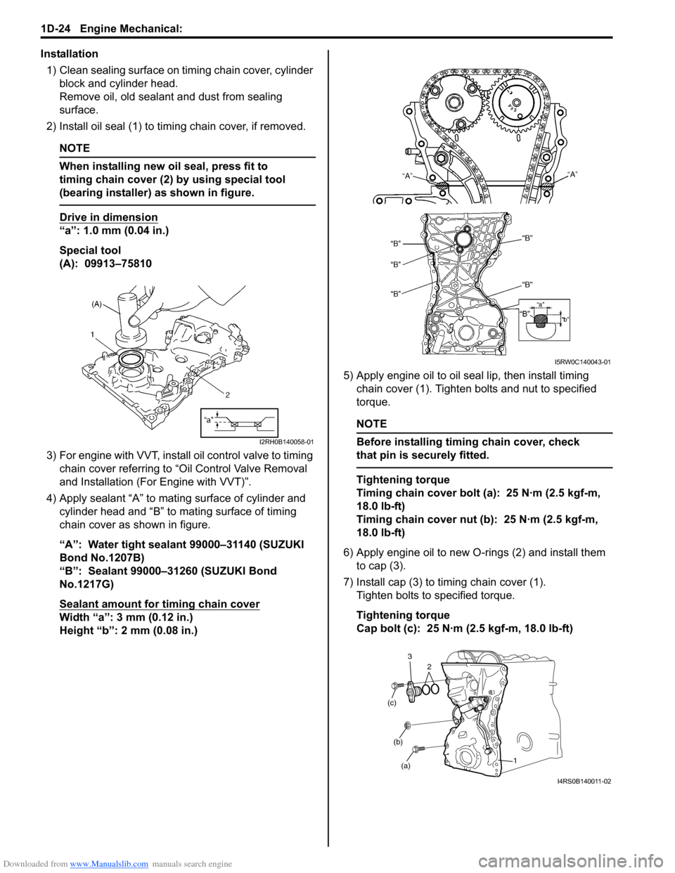
2) Install oil seal (1) to timing chain cover, if removed.
NOTE
When installing new oil seal, press fit to
timing chain cover (2) by using special tool
(bearing installer) as shown in figure.
Drive in dimension
“a”: 1.0 mm (0.04 in.)
Special tool
(A): 09913–75810
3) For engine with VVT, install oil control valve to timing
chain cover referring to “Oil Control Valve Removal
and Installation (For Engine with VVT)”.
4) Apply sealant “A” to mating surface of cylinder and
cylinder head and “B” to mating surface of timing
chain cover as shown in figure.
“A”: Water tight sealant 99000–31140 (SUZUKI
Bond No.1207B)
“B”: Sealant 99000–31260 (SUZUKI Bond
No.1217G)
Sealant amount for timing chain cover
Width “a”: 3 mm (0.12 in.)
Height “b”: 2 mm (0.08 in.)5) Apply engine oil to oil seal lip, then install timing
chain cover (1). Tighten bolts and nut to specified
torque.
NOTE
Before installing timing chain cover, check
that pin is securely fitted.
Tightening torque
Timing chain cover bolt (a): 25 N·m (2.5 kgf-m,
18.0 lb-ft)
Timing chain cover nut (b): 25 N·m (2.5 kgf-m,
18.0 lb-ft)
6) Apply engine oil to new O-rings (2) and install them
to cap (3).
7) Install cap (3) to timing chain cover (1).
Tighten bolts to specified torque.
Tightening torque
Cap bolt (c): 25 N·m (2.5 kgf-m, 18.0 lb-ft)
I2RH0B140058-01
I5RW0C140043-01
(a) (b) (c)
1 2 3
I4RS0B140011-02
Page 307 of 1556
Downloaded from www.Manualslib.com manuals search engine Engine Mechanical: 1D-25
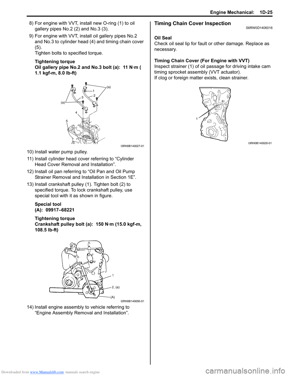
8) For engine with VVT, install new O-ring (1) to oil
gallery pipes No.2 (2) and No.3 (3).
9) For engine with VVT, install oil gallery pipes No.2
and No.3 to cylinder head (4) and timing chain cover
(5).
Tighten bolts to specified torque.
Tightening torque
Oil gallery pipe No.2 and No.3 bolt (a): 11 N·m (
1.1 kgf-m, 8.0 lb-ft)
10) Install water pump pulley.
11) Install cylinder head cover referring to “Cylinder
Head Cover Removal and Installation”.
12) Install oil pan referring to “Oil Pan and Oil Pump
Strainer Removal and Installation in Section 1E”.
13) Install crankshaft pulley (1). Tighten bolt (2) to
specified torque. To lock crankshaft pulley, use
special tool with it as shown in figure.
Special tool
(A): 09917–68221
Tightening torque
Crankshaft pulley bolt (a): 150 N·m (15.0 kgf-m,
108.5 lb-ft)
14) Install engine assembly to vehicle referring to
“Engine Assembly Removal and Installation”.Timing Chain Cover InspectionS6RW0D1406016
Oil Seal
Check oil seal lip for fault or other damage. Replace as
necessary.
Timing Chain Cover (For Engine with VVT)
Inspect strainer (1) of oil passage for driving intake cam
timing sprocket assembly (VVT actuator).
If clog or foreign matter exists, clean strainer.
(a)
(a)1
2
3
4
5
I3RH0B140027-01
I2RH0B140056-01
1
I3RH0B140028-01