Oil pressure switch SUZUKI SX4 2006 1.G Service Owner's Manual
[x] Cancel search | Manufacturer: SUZUKI, Model Year: 2006, Model line: SX4, Model: SUZUKI SX4 2006 1.GPages: 1556, PDF Size: 37.31 MB
Page 288 of 1556
Downloaded from www.Manualslib.com manuals search engine 1D-6 Engine Mechanical:
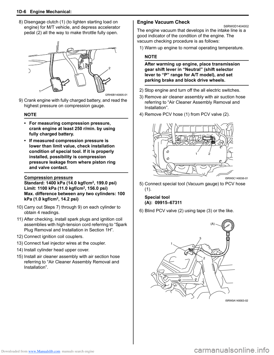
8) Disengage clutch (1) (to lighten starting load on
engine) for M/T vehicle, and depress accelerator
pedal (2) all the way to make throttle fully open.
9) Crank engine with fully charged battery, and read the
highest pressure on compression gauge.
NOTE
• For measuring compression pressure,
crank engine at least 250 r/min. by using
fully charged battery.
• If measured compression pressure is
lower than limit value, check installation
condition of special tool. If it is properly
installed, possibility is compression
pressure leakage from where piston ring
and valve contact.
Compression pressure
Standard: 1400 kPa (14.0 kgf/cm2, 199.0 psi)
Limit: 1100 kPa (11.0 kgf/cm2, 156.0 psi)
Max. difference between any two cylinders: 100
kPa (1.0 kgf/cm
2, 14.2 psi)
10) Carry out Steps 7) through 9) on each cylinder to
obtain 4 readings.
11) After checking, install spark plugs and ignition coil
assemblies with high-tension cord referring to “Spark
Plug Removal and Installation in Section 1H”.
12) Connect ignition coil couplers.
13) Connect fuel injector wires at the coupler.
14) Install cylinder head upper cover.
15) Install air cleaner assembly with air section hose
referring to “Air Cleaner Assembly Removal and
Installation”.
Engine Vacuum CheckS6RW0D1404002
The engine vacuum that develops in the intake line is a
good indicator of the condition of the engine. The
vacuum checking procedure is as follows:
1) Warm up engine to normal operating temperature.
NOTE
After warming up engine, place transmission
gear shift lever in “Neutral” (shift selector
lever to “P” range for A/T model), and set
parking brake and block drive wheels.
2) Stop engine and turn off the all electric switches.
3) Remove air cleaner assembly with air suction hose
referring to “Air Cleaner Assembly Removal and
Installation”.
4) Remove PCV hose (1) from PCV valve (2).
5) Connect special tool (Vacuum gauge) to PCV hose
(1).
Special tool
(A): 09915–67311
6) Blind PCV valve (2) using tape (3) or the like.I2RH0B140005-01
12
I5RW0C140038-01
(A)
1
2
3
I5RW0A140003-02
Page 299 of 1556
Downloaded from www.Manualslib.com manuals search engine Engine Mechanical: 1D-17
Engine Assembly Removal and InstallationS6RW0D1406013
Removal
1) Relieve fuel pressure according to “Fuel Pressure
Relief Procedure in Section 1G”.
2) Disconnect negative and positive cable at battery.
3) Disconnect ECM connectors.
4) Remove battery and battery tray with ECM.
5) Remove right and left side engine under covers.
6) Remove A/C compressor belt by referring to
“Compressor Drive Belt Removal and Installation in
Section 7B” or “Compressor Drive Belt Removal and
Installation in Section 7B”.
7) Drain engine oil referring to “Engine Oil and Filter
Change in Section 0B”.
8) Drain transaxle oil referring to “Manual Transaxle Oil
Change in Section 5B” or “A/T Fluid Change in
Section 5A”.
9) Drain transfer oil referring to “Transfer Oil Change in
Section 3C”.
10) Drain coolant referring to “Cooling System Draining
in Section 1F”
11) Remove air cleaner assembly referring to “Air
Cleaner Assembly Removal and Installation”.
12) With hose connected, detach A/C compressor from
its bracket referring to “Compressor Assembly
Removal and Installation in Section 7B” or
“Compressor Assembly Removal and Installation in
Section 7B”.
CAUTION!
Suspend removed A/C compressor at a place
where no damage will be caused during
removal and installation of engine assembly.
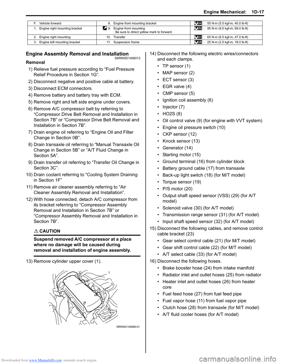
13) Remove cylinder upper cover (1).14) Disconnect the following electric wires/connectors
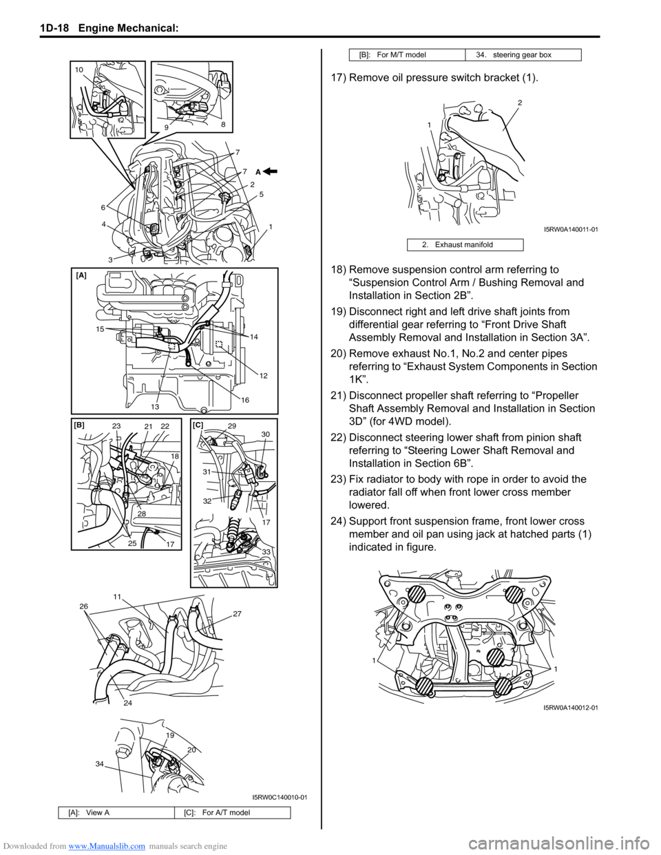
and each clamps.
• TP sensor (1)
• MAP sensor (2)
• ECT sensor (3)
•EGR valve (4)
• CMP sensor (5)
• Ignition coil assembly (6)
• Injector (7)
•HO2S (8)
• Oil control valve (9) (for engine with VVT system)
• Engine oil pressure switch (10)
• CKP sensor (12)
• Knock sensor (13)
• Generator (14)
• Starting motor (15)
• Ground terminal (16) from cylinder block
• Battery ground cable (17) from transaxle
• Back-up light switch (18) (for M/T model)
• Torque sensor (19)
• P/S motor (20)
• Output shaft speed sensor (VSS) (29) (for A/T
model)
• Solenoid valve (30) (for A/T model)
• Transmission range sensor (31) (for A/T model)
• Input shaft speed sensor (32) (for A/T model)
15) Disconnect the following cables, and remove control
cable bracket (23)
• Gear select control cable (21) (for M/T model)
• Gear shift control cable (22) (for M/T model)
• A/T select cable (33) (for A/T model)
16) Disconnect the following hoses.
• Brake booster hose (24) from intake manifold
• Radiator inlet and outlet hoses (25) from radiator
• Heater inlet and outlet hoses (26) from heater
core
• Fuel feed hose (27) from fuel feed pipe
• Fuel vapor hose (11) from fuel vapor pipe
• Clutch hose (28) from transaxle (for M/T model)
• A/T fluid cooler hoses (for A/T model)
F: Vehicle forward 8. Engine front mounting bracket : 55 N⋅m (5.5 kgf-m, 40.0 lb-ft)
1. Engine right mounting bracket 9. Engine front mounting
: Be sure to direct yellow mark to forward.: 95 N⋅m (9.5 kgf-m, 69.0 lb-ft)
2. Engine right mounting 10. Transfer : 65 N⋅m (6.5 kgf-m, 47.0 lb-ft)
3. Engine left mounting bracket 11. Suspension frame : 25 N⋅m (2.5 kgf-m, 18.0 lb-ft)
1
I5RW0A140009-01
Page 300 of 1556
Downloaded from www.Manualslib.com manuals search engine 1D-18 Engine Mechanical:
17) Remove oil pressure switch bracket (1).
18) Remove suspension control arm referring to
“Suspension Control Arm / Bushing Removal and
Installation in Section 2B”.
19) Disconnect right and left drive shaft joints from
differential gear referring to “Front Drive Shaft
Assembly Removal and Installation in Section 3A”.
20) Remove exhaust No.1, No.2 and center pipes
referring to “Exhaust System Components in Section
1K”.
21) Disconnect propeller shaft referring to “Propeller
Shaft Assembly Removal and Installation in Section
3D” (for 4WD model).
22) Disconnect steering lower shaft from pinion shaft
referring to “Steering Lower Shaft Removal and
Installation in Section 6B”.
23) Fix radiator to body with rope in order to avoid the
radiator fall off when front lower cross member
lowered.
24) Support front suspension frame, front lower cross
member and oil pan using jack at hatched parts (1)
indicated in figure.
[A]: View A [C]: For A/T model
6
3 45
1 7 7
2
8
9
10
A
15
14
16
20 19
26
24
27
12
13 [A]
11
34
232122
25
17 2818 [B] [C]
2930
31
32
17
33
I5RW0C140010-01
[B]: For M/T model 34. steering gear box
2. Exhaust manifold
1
2
I5RW0A140011-01
11
I5RW0A140012-01
Page 303 of 1556
Downloaded from www.Manualslib.com manuals search engine Engine Mechanical: 1D-21
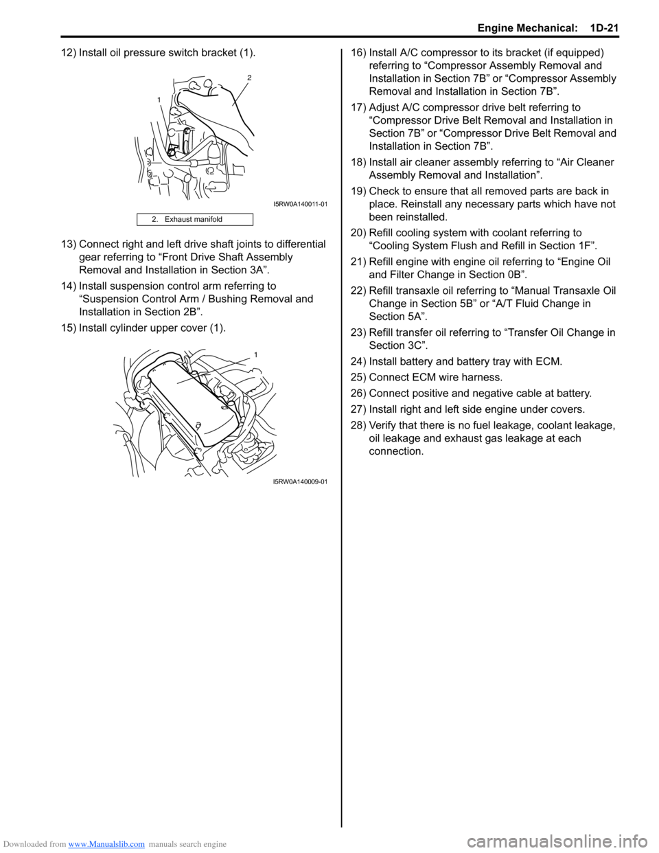
12) Install oil pressure switch bracket (1).
13) Connect right and left drive shaft joints to differential
gear referring to “Front Drive Shaft Assembly
Removal and Installation in Section 3A”.
14) Install suspension control arm referring to
“Suspension Control Arm / Bushing Removal and
Installation in Section 2B”.
15) Install cylinder upper cover (1).16) Install A/C compressor to its bracket (if equipped)
referring to “Compressor Assembly Removal and
Installation in Section 7B” or “Compressor Assembly
Removal and Installation in Section 7B”.
17) Adjust A/C compressor drive belt referring to
“Compressor Drive Belt Removal and Installation in
Section 7B” or “Compressor Drive Belt Removal and
Installation in Section 7B”.
18) Install air cleaner assembly referring to “Air Cleaner
Assembly Removal and Installation”.
19) Check to ensure that all removed parts are back in
place. Reinstall any necessary parts which have not
been reinstalled.
20) Refill cooling system with coolant referring to
“Cooling System Flush and Refill in Section 1F”.
21) Refill engine with engine oil referring to “Engine Oil
and Filter Change in Section 0B”.
22) Refill transaxle oil referring to “Manual Transaxle Oil
Change in Section 5B” or “A/T Fluid Change in
Section 5A”.
23) Refill transfer oil referring to “Transfer Oil Change in
Section 3C”.
24) Install battery and battery tray with ECM.
25) Connect ECM wire harness.
26) Connect positive and negative cable at battery.
27) Install right and left side engine under covers.
28) Verify that there is no fuel leakage, coolant leakage,
oil leakage and exhaust gas leakage at each
connection.
2. Exhaust manifold
1
2
I5RW0A140011-01
1
I5RW0A140009-01
Page 341 of 1556

Downloaded from www.Manualslib.com manuals search engine Engine Mechanical: 1D-59
Main Bearings, Crankshaft and Cylinder Block ComponentsS6RW0D1406037
I6RW0D140003-01
1. CKP sensor
: See “A”11. Rear oil seal 21. Oil filter adapter bolt
2. Knock sensor 12. Input shaft bearing 22. Spring pin
3. Cylinder block 13. Flywheel or drive plate 23. Sensor plate bolt
4. Venturi plug 14. Main bearing cap 24. Oil pressure switch
Page 358 of 1556
Downloaded from www.Manualslib.com manuals search engine 1E-2 Engine Lubrication System:
Diagnostic Information and Procedures
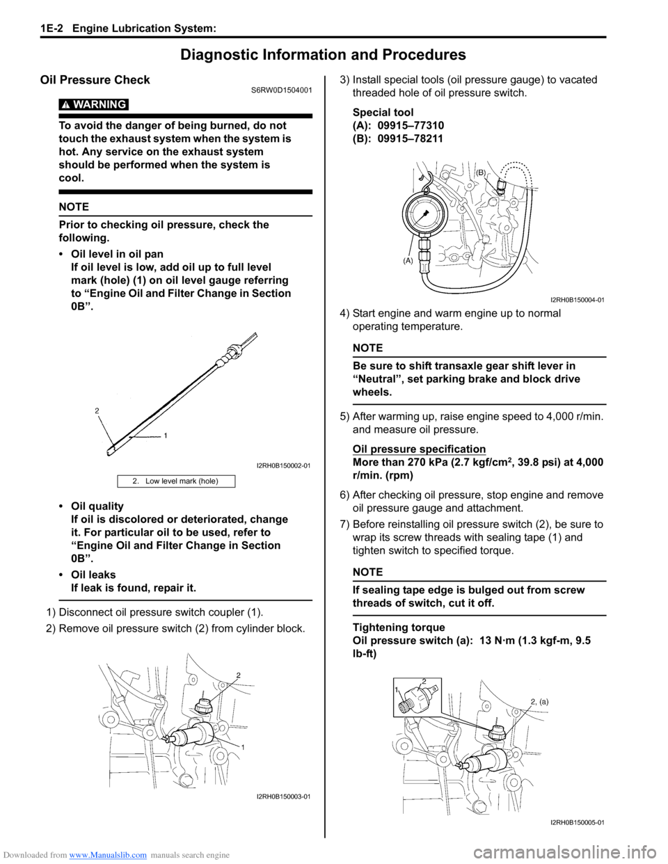
Oil Pressure CheckS6RW0D1504001
WARNING!
To avoid the danger of being burned, do not
touch the exhaust system when the system is
hot. Any service on the exhaust system
should be performed when the system is
cool.
NOTE
Prior to checking oil pressure, check the
following.
• Oil level in oil pan
If oil level is low, add oil up to full level
mark (hole) (1) on oil level gauge referring
to “Engine Oil and Filter Change in Section
0B”.
• Oil quality
If oil is discolored or deteriorated, change
it. For particular oil to be used, refer to
“Engine Oil and Filter Change in Section
0B”.
• Oil leaks
If leak is found, repair it.
1) Disconnect oil pressure switch coupler (1).
2) Remove oil pressure switch (2) from cylinder block.3) Install special tools (oil pressure gauge) to vacated
threaded hole of oil pressure switch.
Special tool
(A): 09915–77310
(B): 09915–78211
4) Start engine and warm engine up to normal
operating temperature.
NOTE
Be sure to shift transaxle gear shift lever in
“Neutral”, set parking brake and block drive
wheels.
5) After warming up, raise engine speed to 4,000 r/min.
and measure oil pressure.
Oil pressure specification
More than 270 kPa (2.7 kgf/cm2, 39.8 psi) at 4,000
r/min. (rpm)
6) After checking oil pressure, stop engine and remove
oil pressure gauge and attachment.
7) Before reinstalling oil pressure switch (2), be sure to
wrap its screw threads with sealing tape (1) and
tighten switch to specified torque.
NOTE
If sealing tape edge is bulged out from screw
threads of switch, cut it off.
Tightening torque
Oil pressure switch (a): 13 N·m (1.3 kgf-m, 9.5
lb-ft)
2. Low level mark (hole)
I2RH0B150002-01
I2RH0B150003-01
I2RH0B150004-01
I2RH0B150005-01
Page 359 of 1556
Downloaded from www.Manualslib.com manuals search engine Engine Lubrication System: 1E-3
8) Start engine and check oil pressure switch for oil
leakage. If oil leakage is found, repair it.
9) Connect oil pressure switch coupler (1).
Repair Instructions
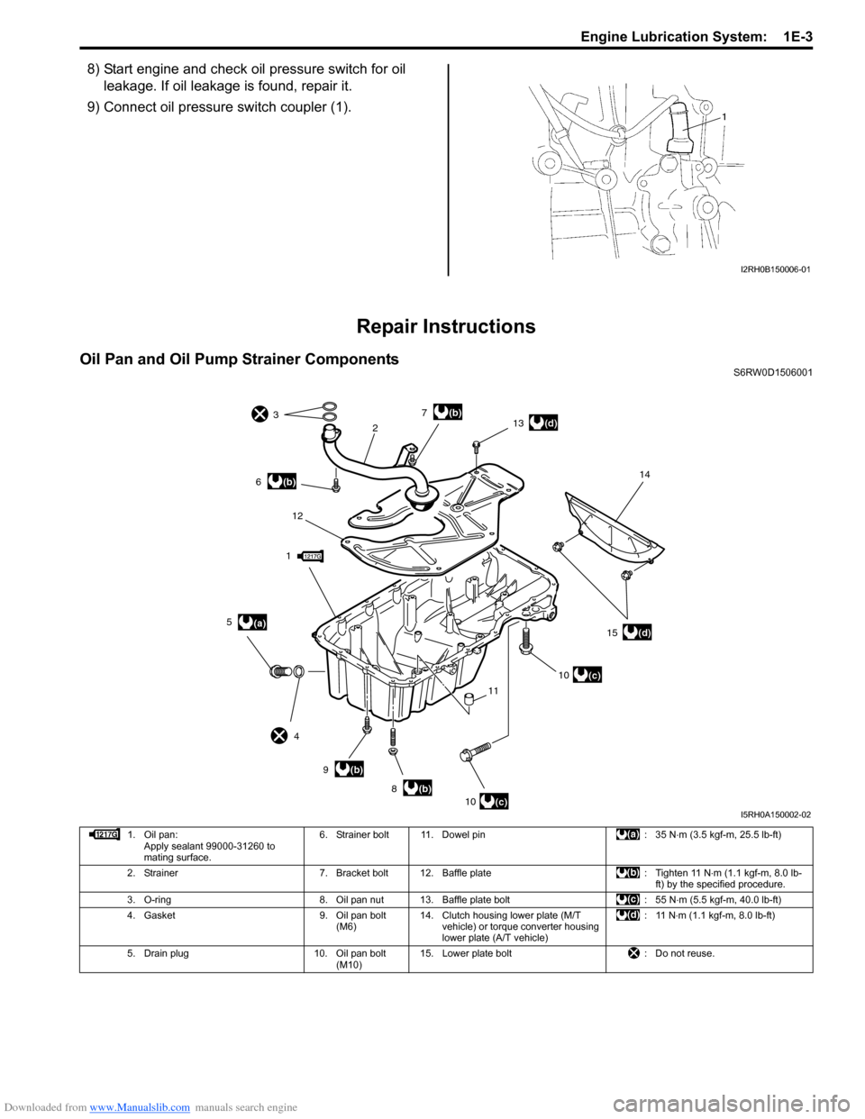
Oil Pan and Oil Pump Strainer ComponentsS6RW0D1506001
I2RH0B150006-01
1
23
4
(a) 5
(b) 6
(b) 8
(b) 9
(b) 7
10
(c)10
(c)
11 12
(d) 13
(d) 1514
I5RH0A150002-02
1. Oil pan:
Apply sealant 99000-31260 to
mating surface.6. Strainer bolt 11. Dowel pin : 35 N⋅m (3.5 kgf-m, 25.5 lb-ft)
2. Strainer 7. Bracket bolt 12. Baffle plate : Tighten 11 N⋅m (1.1 kgf-m, 8.0 lb-
ft) by the specified procedure.
3. O-ring 8. Oil pan nut 13. Baffle plate bolt : 55 N⋅m (5.5 kgf-m, 40.0 lb-ft)
4. Gasket 9. Oil pan bolt
(M6)14. Clutch housing lower plate (M/T
vehicle) or torque converter housing
lower plate (A/T vehicle):11 N⋅m (1.1 kgf-m, 8.0 lb-ft)
5. Drain plug 10. Oil pan bolt
(M10)15. Lower plate bolt : Do not reuse.
Page 365 of 1556
Downloaded from www.Manualslib.com manuals search engine Engine Lubrication System: 1E-9
Specifications
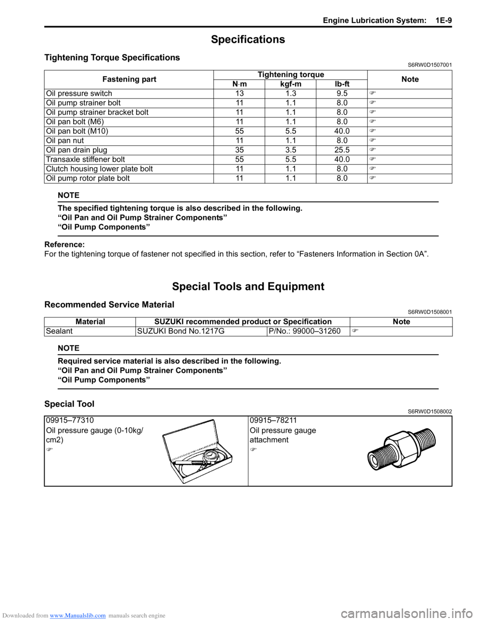
Tightening Torque SpecificationsS6RW0D1507001
NOTE
The specified tightening torque is also described in the following.
“Oil Pan and Oil Pump Strainer Components”
“Oil Pump Components”
Reference:
For the tightening torque of fastener not specified in this section, refer to “Fasteners Information in Section 0A”.
Special Tools and Equipment
Recommended Service MaterialS6RW0D1508001
NOTE
Required service material is also described in the following.
“Oil Pan and Oil Pump Strainer Components”
“Oil Pump Components”
Special ToolS6RW0D1508002
Fastening partTightening torque
Note
N⋅mkgf-mlb-ft
Oil pressure switch 13 1.3 9.5)
Oil pump strainer bolt 11 1.1 8.0)
Oil pump strainer bracket bolt 11 1.1 8.0)
Oil pan bolt (M6) 11 1.1 8.0)
Oil pan bolt (M10) 55 5.5 40.0)
Oil pan nut 11 1.1 8.0)
Oil pan drain plug 35 3.5 25.5)
Transaxle stiffener bolt 55 5.5 40.0)
Clutch housing lower plate bolt 11 1.1 8.0)
Oil pump rotor plate bolt 11 1.1 8.0)
Material SUZUKI recommended product or Specification Note
Sealant SUZUKI Bond No.1217G P/No.: 99000–31260)
09915–77310 09915–78211
Oil pressure gauge (0-10kg/
cm2)Oil pressure gauge
attachment
))
Page 499 of 1556
Downloaded from www.Manualslib.com manuals search engine Differential: 3B-2
General Description
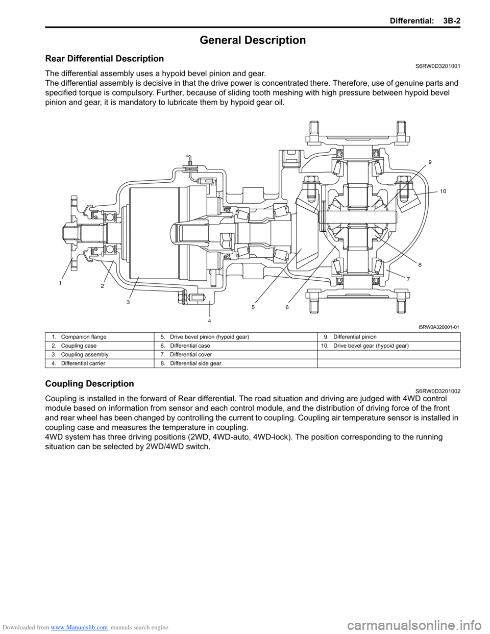
Rear Differential DescriptionS6RW0D3201001
The differential assembly uses a hypoid bevel pinion and gear.
The differential assembly is decisive in that the drive power is concentrated there. Therefore, use of genuine parts and
specified torque is compulsory. Further, because of sliding tooth meshing with high pressure between hypoid bevel
pinion and gear, it is mandatory to lubricate them by hypoid gear oil.
Coupling DescriptionS6RW0D3201002
Coupling is installed in the forward of Rear differential. The road situation and driving are judged with 4WD control
module based on information from sensor and each control module, and the distribution of driving force of the front
and rear wheel has been changed by controlling the current to coupling. Coupling air temperature sensor is installed in
coupling case and measures the temperature in coupling.
4WD system has three driving positions (2WD, 4WD-auto, 4WD-lock). The position corresponding to the running
situation can be selected by 2WD/4WD switch.
1
2
3
4567810 9
I5RW0A320001-01
1. Companion flange 5. Drive bevel pinion (hypoid gear) 9. Differential pinion
2. Coupling case 6. Differential case 10. Drive bevel gear (hypoid gear)
3. Coupling assembly 7. Differential cover
4. Differential carrier 8. Differential side gear
Page 646 of 1556
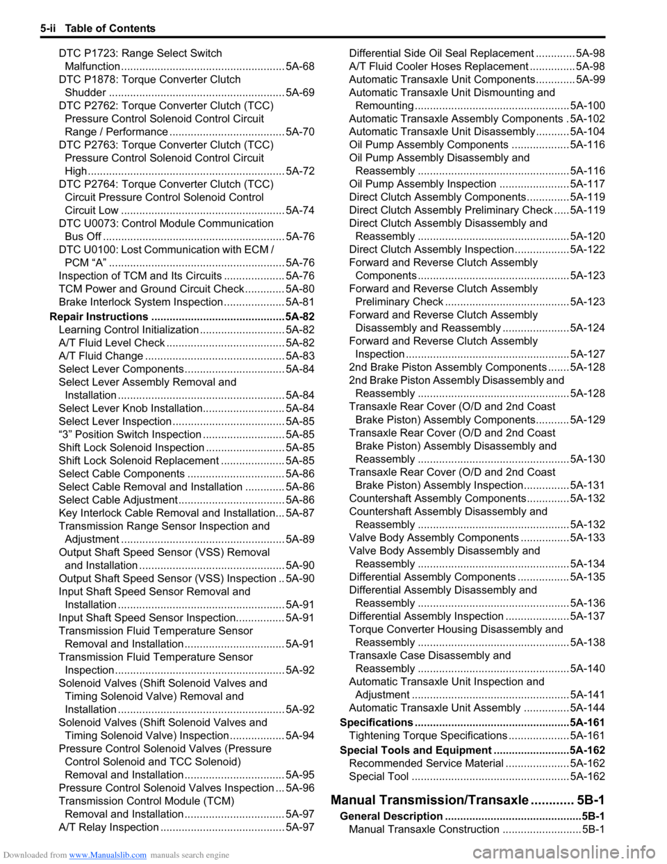
Downloaded from www.Manualslib.com manuals search engine 5-ii Table of Contents
DTC P1723: Range Select Switch
Malfunction ...................................................... 5A-68
DTC P1878: Torque Converter Clutch
Shudder .......................................................... 5A-69
DTC P2762: Torque Converter Clutch (TCC)
Pressure Control Solenoid Control Circuit
Range / Performance ...................................... 5A-70
DTC P2763: Torque Converter Clutch (TCC)
Pressure Control Solenoid Control Circuit
High ................................................................. 5A-72
DTC P2764: Torque Converter Clutch (TCC)
Circuit Pressure Control Solenoid Control
Circuit Low ...................................................... 5A-74
DTC U0073: Control Module Communication
Bus Off ............................................................ 5A-76
DTC U0100: Lost Communication with ECM /
PCM “A” .......................................................... 5A-76
Inspection of TCM and Its Circuits .................... 5A-76
TCM Power and Ground Circuit Check ............. 5A-80
Brake Interlock System Inspection .................... 5A-81
Repair Instructions ............................................5A-82
Learning Control Initialization ............................ 5A-82
A/T Fluid Level Check ....................................... 5A-82
A/T Fluid Change .............................................. 5A-83
Select Lever Components ................................. 5A-84
Select Lever Assembly Removal and
Installation ....................................................... 5A-84
Select Lever Knob Installation........................... 5A-84
Select Lever Inspection ..................................... 5A-85
“3” Position Switch Inspection ........................... 5A-85
Shift Lock Solenoid Inspection .......................... 5A-85
Shift Lock Solenoid Replacement ..................... 5A-85
Select Cable Components ................................ 5A-86
Select Cable Removal and Installation ............. 5A-86
Select Cable Adjustment ................................... 5A-86
Key Interlock Cable Removal and Installation... 5A-87
Transmission Range Sensor Inspection and
Adjustment ...................................................... 5A-89
Output Shaft Speed Sensor (VSS) Removal
and Installation ................................................ 5A-90
Output Shaft Speed Sensor (VSS) Inspection .. 5A-90
Input Shaft Speed Sensor Removal and
Installation ....................................................... 5A-91
Input Shaft Speed Sensor Inspection................ 5A-91
Transmission Fluid Temperature Sensor
Removal and Installation ................................. 5A-91
Transmission Fluid Temperature Sensor
Inspection ........................................................ 5A-92
Solenoid Valves (Shift Solenoid Valves and
Timing Solenoid Valve) Removal and
Installation ....................................................... 5A-92
Solenoid Valves (Shift Solenoid Valves and
Timing Solenoid Valve) Inspection .................. 5A-94
Pressure Control Solenoid Valves (Pressure
Control Solenoid and TCC Solenoid)
Removal and Installation ................................. 5A-95
Pressure Control Solenoid Valves Inspection ... 5A-96
Transmission Control Module (TCM)
Removal and Installation ................................. 5A-97
A/T Relay Inspection ......................................... 5A-97Differential Side Oil Seal Replacement ............. 5A-98
A/T Fluid Cooler Hoses Replacement ............... 5A-98
Automatic Transaxle Unit Components............. 5A-99
Automatic Transaxle Unit Dismounting and
Remounting ................................................... 5A-100
Automatic Transaxle Assembly Components . 5A-102
Automatic Transaxle Unit Disassembly........... 5A-104
Oil Pump Assembly Components ................... 5A-116
Oil Pump Assembly Disassembly and
Reassembly .................................................. 5A-116
Oil Pump Assembly Inspection ....................... 5A-117
Direct Clutch Assembly Components.............. 5A-119
Direct Clutch Assembly Preliminary Check ..... 5A-119
Direct Clutch Assembly Disassembly and
Reassembly .................................................. 5A-120
Direct Clutch Assembly Inspection.................. 5A-122
Forward and Reverse Clutch Assembly
Components .................................................. 5A-123
Forward and Reverse Clutch Assembly
Preliminary Check ......................................... 5A-123
Forward and Reverse Clutch Assembly
Disassembly and Reassembly ...................... 5A-124
Forward and Reverse Clutch Assembly
Inspection ...................................................... 5A-127
2nd Brake Piston Assembly Components ....... 5A-128
2nd Brake Piston Assembly Disassembly and
Reassembly .................................................. 5A-128
Transaxle Rear Cover (O/D and 2nd Coast
Brake Piston) Assembly Components........... 5A-129
Transaxle Rear Cover (O/D and 2nd Coast
Brake Piston) Assembly Disassembly and
Reassembly .................................................. 5A-130
Transaxle Rear Cover (O/D and 2nd Coast
Brake Piston) Assembly Inspection............... 5A-131
Countershaft Assembly Components.............. 5A-132
Countershaft Assembly Disassembly and
Reassembly .................................................. 5A-132
Valve Body Assembly Components ................ 5A-133
Valve Body Assembly Disassembly and
Reassembly .................................................. 5A-134
Differential Assembly Components ................. 5A-135
Differential Assembly Disassembly and
Reassembly .................................................. 5A-136
Differential Assembly Inspection ..................... 5A-137
Torque Converter Housing Disassembly and
Reassembly .................................................. 5A-138
Transaxle Case Disassembly and
Reassembly .................................................. 5A-140
Automatic Transaxle Unit Inspection and
Adjustment .................................................... 5A-141
Automatic Transaxle Unit Assembly ............... 5A-144
Specifications ...................................................5A-161
Tightening Torque Specifications .................... 5A-161
Special Tools and Equipment .........................5A-162
Recommended Service Material ..................... 5A-162
Special Tool .................................................... 5A-162
Manual Transmission/Transaxle ............ 5B-1
General Description .............................................5B-1
Manual Transaxle Construction .......................... 5B-1