oil filter SUZUKI SX4 2006 1.G Service Owner's Manual
[x] Cancel search | Manufacturer: SUZUKI, Model Year: 2006, Model line: SX4, Model: SUZUKI SX4 2006 1.GPages: 1556, PDF Size: 37.31 MB
Page 303 of 1556
Downloaded from www.Manualslib.com manuals search engine Engine Mechanical: 1D-21
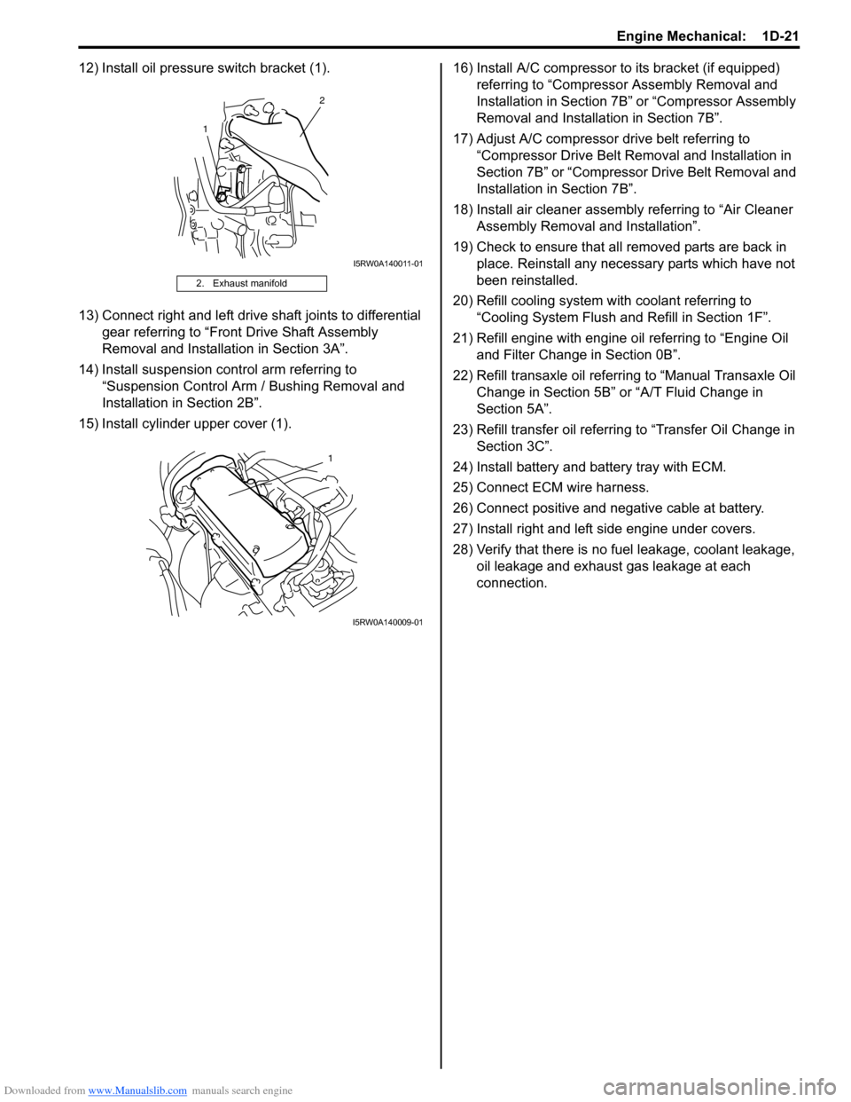
12) Install oil pressure switch bracket (1).
13) Connect right and left drive shaft joints to differential
gear referring to “Front Drive Shaft Assembly
Removal and Installation in Section 3A”.
14) Install suspension control arm referring to
“Suspension Control Arm / Bushing Removal and
Installation in Section 2B”.
15) Install cylinder upper cover (1).16) Install A/C compressor to its bracket (if equipped)
referring to “Compressor Assembly Removal and
Installation in Section 7B” or “Compressor Assembly
Removal and Installation in Section 7B”.
17) Adjust A/C compressor drive belt referring to
“Compressor Drive Belt Removal and Installation in
Section 7B” or “Compressor Drive Belt Removal and
Installation in Section 7B”.
18) Install air cleaner assembly referring to “Air Cleaner
Assembly Removal and Installation”.
19) Check to ensure that all removed parts are back in
place. Reinstall any necessary parts which have not
been reinstalled.
20) Refill cooling system with coolant referring to
“Cooling System Flush and Refill in Section 1F”.
21) Refill engine with engine oil referring to “Engine Oil
and Filter Change in Section 0B”.
22) Refill transaxle oil referring to “Manual Transaxle Oil
Change in Section 5B” or “A/T Fluid Change in
Section 5A”.
23) Refill transfer oil referring to “Transfer Oil Change in
Section 3C”.
24) Install battery and battery tray with ECM.
25) Connect ECM wire harness.
26) Connect positive and negative cable at battery.
27) Install right and left side engine under covers.
28) Verify that there is no fuel leakage, coolant leakage,
oil leakage and exhaust gas leakage at each
connection.
2. Exhaust manifold
1
2
I5RW0A140011-01
1
I5RW0A140009-01
Page 341 of 1556

Downloaded from www.Manualslib.com manuals search engine Engine Mechanical: 1D-59
Main Bearings, Crankshaft and Cylinder Block ComponentsS6RW0D1406037
I6RW0D140003-01
1. CKP sensor
: See “A”11. Rear oil seal 21. Oil filter adapter bolt
2. Knock sensor 12. Input shaft bearing 22. Spring pin
3. Cylinder block 13. Flywheel or drive plate 23. Sensor plate bolt
4. Venturi plug 14. Main bearing cap 24. Oil pressure switch
Page 342 of 1556
Downloaded from www.Manualslib.com manuals search engine 1D-60 Engine Mechanical:
Main Bearings, Crankshaft and Cylinder Block
Removal and Installation
S6RW0D1406038
Removal
1) Remove engine assembly from vehicle referring to
“Engine Assembly Removal and Installation”.
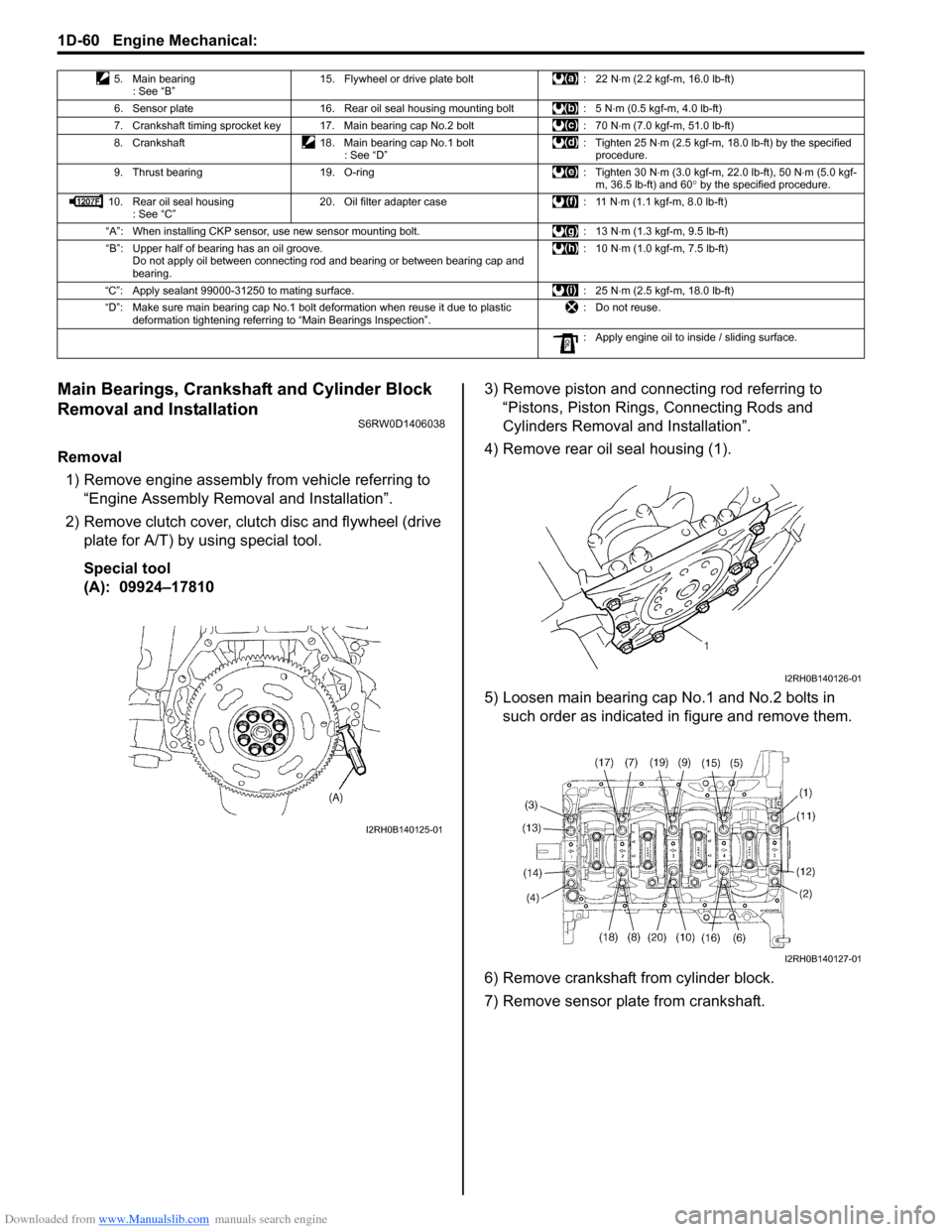
2) Remove clutch cover, clutch disc and flywheel (drive
plate for A/T) by using special tool.
Special tool
(A): 09924–178103) Remove piston and connecting rod referring to
“Pistons, Piston Rings, Connecting Rods and
Cylinders Removal and Installation”.
4) Remove rear oil seal housing (1).
5) Loosen main bearing cap No.1 and No.2 bolts in
such order as indicated in figure and remove them.
6) Remove crankshaft from cylinder block.
7) Remove sensor plate from crankshaft.
5. Main bearing
: See “B”15. Flywheel or drive plate bolt : 22 N⋅m (2.2 kgf-m, 16.0 lb-ft)
6. Sensor plate 16. Rear oil seal housing mounting bolt : 5 N⋅m (0.5 kgf-m, 4.0 lb-ft)
7. Crankshaft timing sprocket key 17. Main bearing cap No.2 bolt : 70 N⋅m (7.0 kgf-m, 51.0 lb-ft)
8. Crankshaft 18. Main bearing cap No.1 bolt
: See “D”: Tighten 25 N⋅m (2.5 kgf-m, 18.0 lb-ft) by the specified
procedure.
9. Thrust bearing 19. O-ring : Tighten 30 N⋅m (3.0 kgf-m, 22.0 lb-ft), 50 N⋅m (5.0 kgf-
m, 36.5 lb-ft) and 60° by the specified procedure.
10. Rear oil seal housing
: See “C”20. Oil filter adapter case : 11 N⋅m (1.1 kgf-m, 8.0 lb-ft)
“A”: When installing CKP sensor, use new sensor mounting bolt. : 13 N⋅m (1.3 kgf-m, 9.5 lb-ft)
“B”: Upper half of bearing has an oil groove.
Do not apply oil between connecting rod and bearing or between bearing cap and
bearing.:10 N⋅m (1.0 kgf-m, 7.5 lb-ft)
“C”: Apply sealant 99000-31250 to mating surface. : 25 N⋅m (2.5 kgf-m, 18.0 lb-ft)
“D”: Make sure main bearing cap No.1 bolt deformation when reuse it due to plastic
deformation tightening referring to “Main Bearings Inspection”.: Do not reuse.
: Apply engine oil to inside / sliding surface.
I2RH0B140125-01
I2RH0B140126-01
I2RH0B140127-01
Page 357 of 1556

Downloaded from www.Manualslib.com manuals search engine Engine Lubrication System: 1E-1
Engine
Engine Lubrication System
General Description
Engine Lubrication DescriptionS6RW0D1501001
The oil pump is of a trochoid type, and mounted on the crankshaft. Oil is drawn up through the oil pump strainer and
passed through the pump to the oil filter.
The filtered oil flows into two paths in cylinder block.
In one path, oil reaches the crankshaft journal bearings. Oil from the crankshaft journal bearings is supplied to the
connecting rod bearings by means of intersecting passages drilled in the crankshaft, and then injected from the big
end of connecting rod to lubricate piston, rings and cylinder wall.
In the other path oil goes up to the cylinder head and lubricates valves and camshafts, etc., after passing through the
internal oil way of camshafts.
An oil relief valve is provided on the oil pump. This valve starts relieving oil pressure when the pressure exceeds
specified pressure.
I5RW0C150002-01
Page 358 of 1556
Downloaded from www.Manualslib.com manuals search engine 1E-2 Engine Lubrication System:
Diagnostic Information and Procedures
Oil Pressure CheckS6RW0D1504001
WARNING!
To avoid the danger of being burned, do not
touch the exhaust system when the system is
hot. Any service on the exhaust system
should be performed when the system is
cool.
NOTE
Prior to checking oil pressure, check the
following.
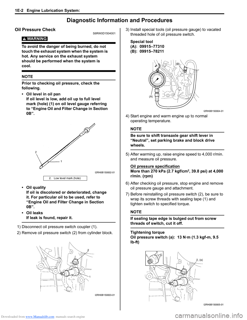
• Oil level in oil pan
If oil level is low, add oil up to full level
mark (hole) (1) on oil level gauge referring
to “Engine Oil and Filter Change in Section
0B”.
• Oil quality
If oil is discolored or deteriorated, change
it. For particular oil to be used, refer to
“Engine Oil and Filter Change in Section
0B”.
• Oil leaks
If leak is found, repair it.
1) Disconnect oil pressure switch coupler (1).
2) Remove oil pressure switch (2) from cylinder block.3) Install special tools (oil pressure gauge) to vacated
threaded hole of oil pressure switch.
Special tool
(A): 09915–77310
(B): 09915–78211
4) Start engine and warm engine up to normal
operating temperature.
NOTE
Be sure to shift transaxle gear shift lever in
“Neutral”, set parking brake and block drive
wheels.
5) After warming up, raise engine speed to 4,000 r/min.
and measure oil pressure.
Oil pressure specification
More than 270 kPa (2.7 kgf/cm2, 39.8 psi) at 4,000
r/min. (rpm)
6) After checking oil pressure, stop engine and remove
oil pressure gauge and attachment.
7) Before reinstalling oil pressure switch (2), be sure to
wrap its screw threads with sealing tape (1) and
tighten switch to specified torque.
NOTE
If sealing tape edge is bulged out from screw
threads of switch, cut it off.
Tightening torque
Oil pressure switch (a): 13 N·m (1.3 kgf-m, 9.5
lb-ft)
2. Low level mark (hole)
I2RH0B150002-01
I2RH0B150003-01
I2RH0B150004-01
I2RH0B150005-01
Page 361 of 1556
Downloaded from www.Manualslib.com manuals search engine Engine Lubrication System: 1E-5
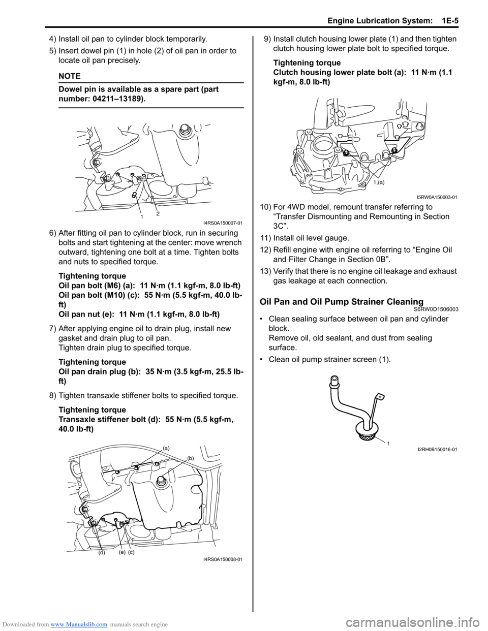
4) Install oil pan to cylinder block temporarily.
5) Insert dowel pin (1) in hole (2) of oil pan in order to
locate oil pan precisely.
NOTE
Dowel pin is available as a spare part (part
number: 04211–13189).
6) After fitting oil pan to cylinder block, run in securing
bolts and start tightening at the center: move wrench
outward, tightening one bolt at a time. Tighten bolts
and nuts to specified torque.
Tightening torque
Oil pan bolt (M6) (a): 11 N·m (1.1 kgf-m, 8.0 lb-ft)
Oil pan bolt (M10) (c): 55 N·m (5.5 kgf-m, 40.0 lb-
ft)
Oil pan nut (e): 11 N·m (1.1 kgf-m, 8.0 lb-ft)
7) After applying engine oil to drain plug, install new
gasket and drain plug to oil pan.
Tighten drain plug to specified torque.
Tightening torque
Oil pan drain plug (b): 35 N·m (3.5 kgf-m, 25.5 lb-
ft)
8) Tighten transaxle stiffener bolts to specified torque.
Tightening torque
Transaxle stiffener bolt (d): 55 N·m (5.5 kgf-m,
40.0 lb-ft)9) Install clutch housing lower plate (1) and then tighten
clutch housing lower plate bolt to specified torque.
Tightening torque
Clutch housing lower plate bolt (a): 11 N·m (1.1
kgf-m, 8.0 lb-ft)
10) For 4WD model, remount transfer referring to
“Transfer Dismounting and Remounting in Section
3C”.
11) Install oil level gauge.
12) Refill engine with engine oil referring to “Engine Oil
and Filter Change in Section 0B”.
13) Verify that there is no engine oil leakage and exhaust
gas leakage at each connection.
Oil Pan and Oil Pump Strainer CleaningS6RW0D1506003
• Clean sealing surface between oil pan and cylinder
block.
Remove oil, old sealant, and dust from sealing
surface.
• Clean oil pump strainer screen (1).
21I4RS0A150007-01
(a)
(b)
(c)(e)
(d)I4RS0A150008-01
1,(a)
I5RW0A150003-01
I2RH0B150016-01
Page 666 of 1556
Downloaded from www.Manualslib.com manuals search engine 5A-18 Automatic Transmission/Transaxle:
Step 2. DTC / Freeze Frame Data Check, Record and
Clearance
First, referring to “DTC Check”, check DTC and pending
DTC. If DTC exists, print or write down DTC and freeze
frame data and then clear malfunction DTC(s) by
referring to “DTC Clearance”. Malfunction DTC indicates
malfunction in the system but it is not possible to know
from it whether the malfunction is occurring now or it
occurred in the past and normal condition has been
restored. In order to know that, check symptom in
question according to Step 5 and then recheck DTC
according to Step 6.
Diagnosing a trouble based on the DTC in this step only
or failure to clear the DTC in this step may result in an
faulty diagnosis, trouble diagnosis of a normal circuit or
difficulty in troubleshooting which is otherwise
unnecessary.
Step 3 and 4. Visual Inspection
As a preliminary step, be sure to perform visual check of
the items that support proper function of the engine and
automatic transaxle referring to “Visual Inspection”.
Step 5. Trouble Symptom Confirmation
Check trouble symptoms based on information obtained
in “Step 1. Customer Complaint Analysis: ” and “Step 2.
DTC / Freeze Frame Data Check, Record and
Clearance: ”.
Also, reconfirm DTC according to “DTC Confirmation
Procedure” described in each DTC flow.
Step 6 and 7. Rechecking and Record of DTC and
Freeze Frame Data
Refer to “DTC Check” for checking procedure.Step 8. A/T Basic Check and A/T Symptom
Diagnosis
Perform basic check of A/T according to “A/T Basic
Check” first. When the end of the flow has been reached,
check the parts of the system suspected as a possible
cause referring to “A/T Symptom Diagnosis” and based
on symptoms appearing on the vehicle (symptoms
obtained through steps of customer complaint analysis,
trouble symptom confirmation and/or A/T basic check)
and repair or replace faulty parts, if any.
Step 9. Troubleshooting for DTC
Based on the DTC indicated in Step 6 / 7 and referring to
“applicable DTC flow”, locate the cause of the trouble,
namely in a sensor, switch, wire harness, connector,
actuator, TCM or other part and repair or replace faulty
parts.
Step 10. Check for Intermittent Problem
Check parts where an intermittent trouble is easy to
occur (e.g. wire harness, connector, etc.), referring to
“Intermittent and Poor Connection Inspection in Section
00” and related circuit of DTC recorded in Step 2.
Step 11. Final Confirmation Test
Confirm that the problem symptom has gone and the
vehicle is free from any abnormal conditions. If what has
been repaired is related to the malfunction DTC, clear
the DTC once and check to ensure that no malfunction
DTC is indicated.
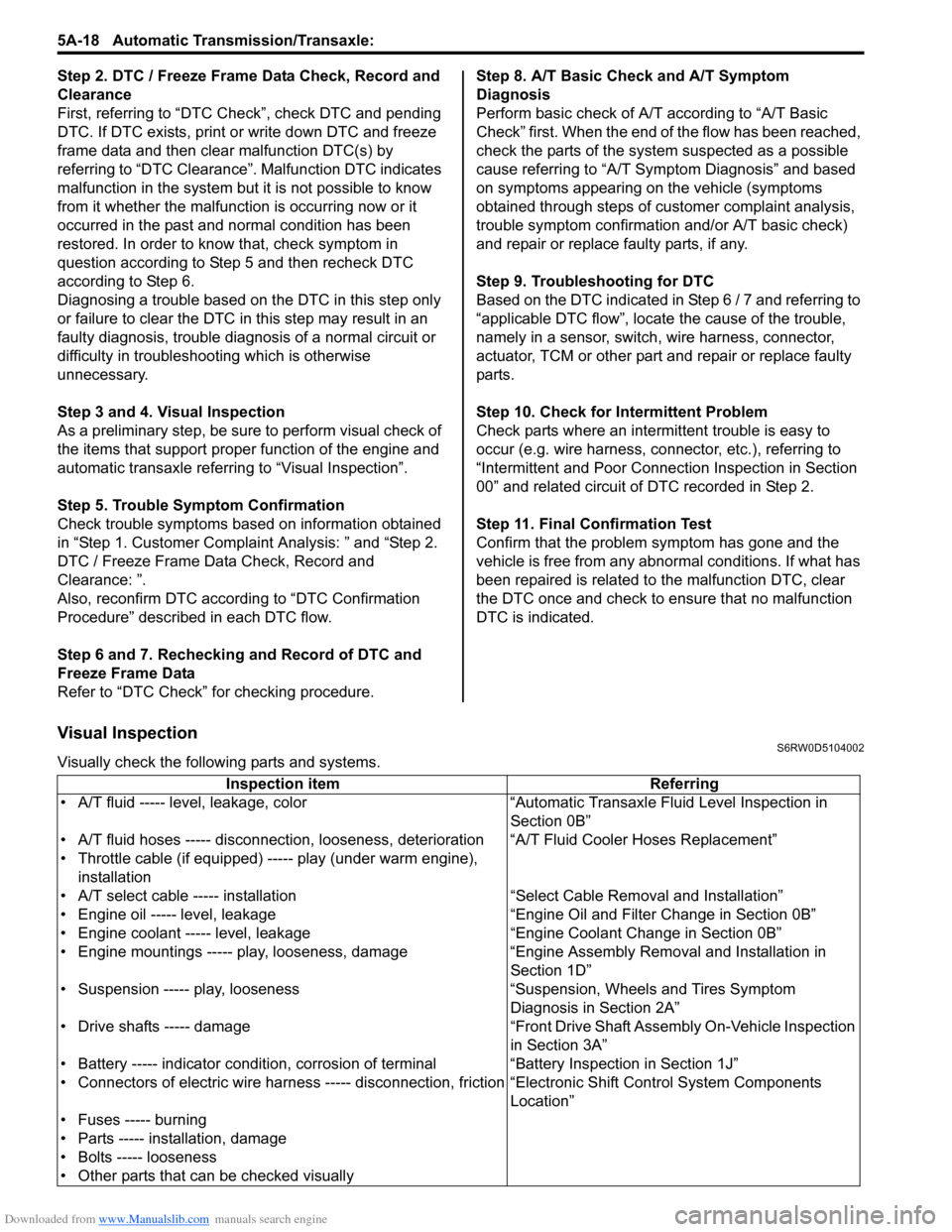
Visual InspectionS6RW0D5104002
Visually check the following parts and systems.
Inspection item Referring
• A/T fluid ----- level, leakage, color “Automatic Transaxle Fluid Level Inspection in
Section 0B”
• A/T fluid hoses ----- disconnection, looseness, deterioration “A/T Fluid Cooler Hoses Replacement”
• Throttle cable (if equipped) ----- play (under warm engine),
installation
• A/T select cable ----- installation “Select Cable Removal and Installation”
• Engine oil ----- level, leakage “Engine Oil and Filter Change in Section 0B”
• Engine coolant ----- level, leakage “Engine Coolant Change in Section 0B”
• Engine mountings ----- play, looseness, damage “Engine Assembly Removal and Installation in
Section 1D”
• Suspension ----- play, looseness “Suspension, Wheels and Tires Symptom
Diagnosis in Section 2A”
• Drive shafts ----- damage “Front Drive Shaft Assembly On-Vehicle Inspection
in Section 3A”
• Battery ----- indicator condition, corrosion of terminal “Battery Inspection in Section 1J”
• Connectors of electric wire harness ----- disconnection, friction “Electronic Shift Control System Components
Location”
• Fuses ----- burning
• Parts ----- installation, damage
• Bolts ----- looseness
• Other parts that can be checked visually
Page 940 of 1556
Downloaded from www.Manualslib.com manuals search engine 7A-12 Heater and Ventilation:
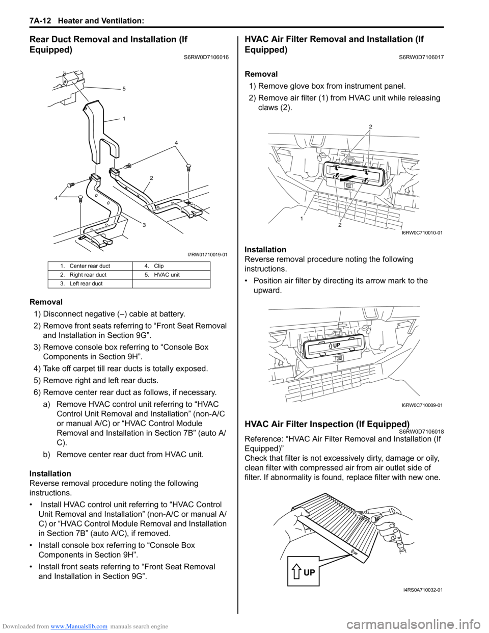
Rear Duct Removal and Installation (If
Equipped)
S6RW0D7106016
Removal
1) Disconnect negative (–) cable at battery.
2) Remove front seats referring to “Front Seat Removal
and Installation in Section 9G”.
3) Remove console box referring to “Console Box
Components in Section 9H”.
4) Take off carpet till rear ducts is totally exposed.
5) Remove right and left rear ducts.
6) Remove center rear duct as follows, if necessary.
a) Remove HVAC control unit referring to “HVAC
Control Unit Removal and Installation” (non-A/C
or manual A/C) or “HVAC Control Module
Removal and Installation in Section 7B” (auto A/
C).
b) Remove center rear duct from HVAC unit.
Installation
Reverse removal procedure noting the following
instructions.
• Install HVAC control unit referring to “HVAC Control
Unit Removal and Installation” (non-A/C or manual A/
C) or “HVAC Control Module Removal and Installation
in Section 7B” (auto A/C), if removed.
• Install console box referring to “Console Box
Components in Section 9H”.
• Install front seats referring to “Front Seat Removal
and Installation in Section 9G”.
HVAC Air Filter Removal and Installation (If
Equipped)
S6RW0D7106017
Removal
1) Remove glove box from instrument panel.
2) Remove air filter (1) from HVAC unit while releasing
claws (2).
Installation
Reverse removal procedure noting the following
instructions.
• Position air filter by directing its arrow mark to the
upward.
HVAC Air Filter Inspection (If Equipped)S6RW0D7106018
Reference: “HVAC Air Filter Removal and Installation (If
Equipped)”
Check that filter is not excessively dirty, damage or oily,
clean filter with compressed air from air outlet side of
filter. If abnormality is found, replace filter with new one.
1. Center rear duct 4. Clip
2. Right rear duct 5. HVAC unit
3. Left rear duct
324 5
1
4
I7RW01710019-01
12
2
I6RW0C710010-01
I6RW0C710009-01
I4RS0A710032-01
Page 942 of 1556

Downloaded from www.Manualslib.com manuals search engine 7B-2 Air Conditioning System: Manual Type
Refrigerant Recovery
When discharging refrigerant out of A/C system, always recover it by using refrigerant recovery and recycling
equipment because discharging refrigerant HFC-134a (R-134a) into atmosphere would cause adverse effect to
environments referring to “Recovery” in “Operation Procedure for Refrigerant Charge”.
Refrigerant Charge
After performing compressor oil replenishment and evacuation, charge a proper amount of refrigerant to A/C system
referring to “Charge” in “Operation Procedure for Refrigerant Charge”.
General Description
Sub-Cool A/C System DescriptionS6RW0D7211001
In the sub-cool A/C system (condenser integrated with receiver / dryer), the inside of the condenser is divided into the
condensation part and the sub-cooler part, and the receiver / dryer is located between those. In the receiver / dryer,
the refrigerant is separated into the vapor refrigerant and the liquid refrigerant. Only the liquid refrigerant is delivered to
the sub-cooler part of the condenser. The refrigerant is supercooled by the sub-cooler part of the condenser.
I5RW0A721003-02
[A]: Liquid 2. Magnet clutch 6. Expansion valve 10. Desiccant
[B]: Vapor 3. Condenser 7. A/C evaporator 11. Filter
[C]: Superheated vapor 4. Receiver/dryer 8. Condensation part 12. Vapor refrigerant
1. Compressor 5. Refrigerant pressure sensor 9. Sub-cooler part 13. Liquid refrigerant
Page 952 of 1556
Downloaded from www.Manualslib.com manuals search engine 7B-12 Air Conditioning System: Manual Type
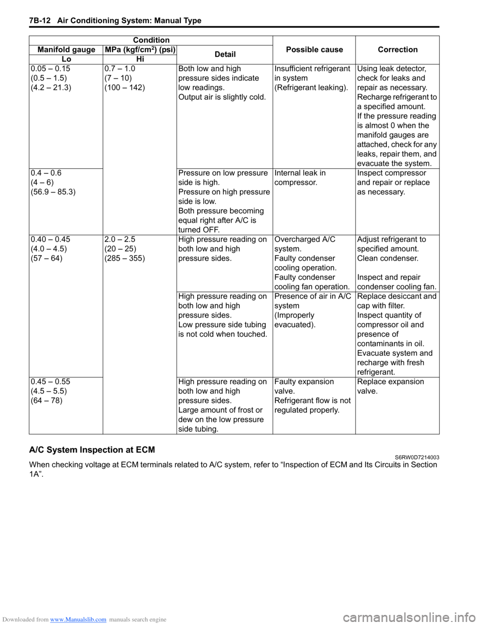
A/C System Inspection at ECMS6RW0D7214003
When checking voltage at ECM terminals related to A/C system, refer to “Inspection of ECM and Its Circuits in Section
1A”.0.05 – 0.15
(0.5 – 1.5)
(4.2 – 21.3)0.7 – 1.0
(7 – 10)
(100 – 142)Both low and high
pressure sides indicate
low readings.
Output air is slightly cold.Insufficient refrigerant
in system
(Refrigerant leaking).Using leak detector,
check for leaks and
repair as necessary.
Recharge refrigerant to
a specified amount.
If the pressure reading
is almost 0 when the
manifold gauges are
attached, check for any
leaks, repair them, and
evacuate the system.
0.4 – 0.6
(4 – 6)
(56.9 – 85.3)Pressure on low pressure
side is high.
Pressure on high pressure
side is low.
Both pressure becoming
equal right after A/C is
turned OFF.Internal leak in
compressor.Inspect compressor
and repair or replace
as necessary.
0.40 – 0.45
(4.0 – 4.5)
(57 – 64)2.0 – 2.5
(20 – 25)
(285 – 355)High pressure reading on
both low and high
pressure sides.Overcharged A/C
system.Adjust refrigerant to
specified amount.
Faulty condenser
cooling operation.Clean condenser.
Faulty condenser
cooling fan operation.Inspect and repair
condenser cooling fan.
High pressure reading on
both low and high
pressure sides.
Low pressure side tubing
is not cold when touched.Presence of air in A/C
system
(Improperly
evacuated).Replace desiccant and
cap with filter.
Inspect quantity of
compressor oil and
presence of
contaminants in oil.
Evacuate system and
recharge with fresh
refrigerant.
0.45 – 0.55
(4.5 – 5.5)
(64 – 78)High pressure reading on
both low and high
pressure sides.
Large amount of frost or
dew on the low pressure
side tubing.Faulty expansion
valve.
Refrigerant flow is not
regulated properly.Replace expansion
valve. Condition
Possible cause Correction Manifold gauge MPa (kgf/cm
2) (psi)
Detail
Lo Hi