AIR SUZUKI SX4 2006 1.G Service Workshop Manual
[x] Cancel search | Manufacturer: SUZUKI, Model Year: 2006, Model line: SX4, Model: SUZUKI SX4 2006 1.GPages: 1556, PDF Size: 37.31 MB
Page 770 of 1556

Downloaded from www.Manualslib.com manuals search engine 5A-122 Automatic Transmission/Transaxle:
Direct Clutch Assembly InspectionS6RW0D5106038
Clutch Discs, Plates and Retaining Plate
Check that sliding surfaces of discs, separator plates
and retaining plate are not worn hard or burnt. If
necessary, replace.
NOTE
• If disc lining is exfoliated, discolored,
replace all discs.
• Before assembling new discs, soak them
in A/T fluid for at least two hours.
Direct Clutch Return Spring Subassembly
Measure free length of direct clutch return spring
subassembly.
Direct clutch return spring subassembly free length
“a”: 36.04 mm (1.419 in.)
NOTE
Do not apply excessive force when
measuring spring free length. Perform
measurement at several points.
Direct Clutch Piston
Shake direct clutch piston lightly and check that check
ball (1) is not stuck.
Blow in low pressure air (Max. 100 kPa, 1 kg/cm
2, 15 psi)
to check ball to check that there is no leakage.
I2RH0B510172-01
I2RH0B510173-01
I2RH0B510174-01
Page 771 of 1556

Downloaded from www.Manualslib.com manuals search engine Automatic Transmission/Transaxle: 5A-123
Forward and Reverse Clutch Assembly ComponentsS6RW0D5106039
Forward and Reverse Clutch Assembly
Preliminary Check
S6RW0D5106040
1) Install forward and reverse clutch assembly (1) to
transaxle rear cover (2), blow in compressed air (400
– 800 kPa, 4 – 8 kg/cm
2, 57 – 113 psi) through oil
hole (4) of transaxle rear cover with the special tool
attached on the upper surface of reverse clutch
retaining plate (3), and measure reverse clutch
piston stroke.
If piston stroke exceeds specified value,
disassemble, inspect and replace inner parts.
Special tool
(A): 09900–20607
(B): 09900–20701Reverse clutch piston stroke
1.20 – 1.60 mm (0.047 – 0.063 in.)
I3RM0B510061-01
1. Forward clutch balancer 8. Intermediate shaft seal ring 15. Forward clutch retaining plate
2. Forward clutch return spring subassembly 9. Reverse clutch plate snap ring 16. Forward clutch disc
3. Forward clutch piston 10. Reverse clutch retaining plate 17. Forward clutch separator plate
4. Forward clutch piston O-ring 11. Reverse clutch separator plate 18. Balancer snap ring
5. Forward clutch drum 12. Reverse clutch disc : Apply automatic transaxle fluid.
6. Forward clutch drum O-ring 13. Reverse clutch cushion plate : Do not reuse.
7. Intermediate shaft subassembly 14. Forward clutch plate snap ring
I2RH0B510176-01
Page 772 of 1556
Downloaded from www.Manualslib.com manuals search engine 5A-124 Automatic Transmission/Transaxle:
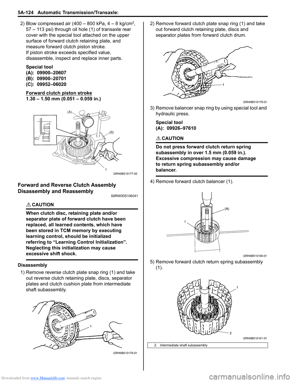
2) Blow compressed air (400 – 800 kPa, 4 – 8 kg/cm2,
57 – 113 psi) through oil hole (1) of transaxle rear
cover with the special tool attached on the upper
surface of forward clutch retaining plate, and
measure forward clutch piston stroke.
If piston stroke exceeds specified value,
disassemble, inspect and replace inner parts.
Special tool
(A): 09900–20607
(B): 09900–20701
(C): 09952–06020
Forward clutch piston stroke
1.30 – 1.50 mm (0.051 – 0.059 in.)
Forward and Reverse Clutch Assembly
Disassembly and Reassembly
S6RW0D5106041
CAUTION!
When clutch disc, retaining plate and/or
separator plate of forward clutch have been
replaced, all learned contents, which have
been stored in TCM memory by executing
learning control, should be initialized
referring to “Learning Control Initialization”.
Neglecting this initialization may cause
excessive shift shock.
Disassembly
1) Remove reverse clutch plate snap ring (1) and take
out reverse clutch retaining plate, discs, separator
plates and clutch cushion plate from intermediate
shaft subassembly.2) Remove forward clutch plate snap ring (1) and take
out forward clutch retaining plate, discs and
separator plates from forward clutch drum.
3) Remove balancer snap ring by using special tool and
hydraulic press.
Special tool
(A): 09926–97610
CAUTION!
Do not press forward clutch return spring
subassembly in over 1.5 mm (0.059 in.).
Excessive compression may cause damage
to return spring subassembly and/or
balancer.
4) Remove forward clutch balancer (1).
5) Remove forward clutch return spring subassembly
(1).
I2RH0B510177-02
I2RH0B510178-01
2. Intermediate shaft subassembly
I2RH0B510179-01
I2RH0B510180-01
I2RH0B510181-01
Page 773 of 1556
Downloaded from www.Manualslib.com manuals search engine Automatic Transmission/Transaxle: 5A-125
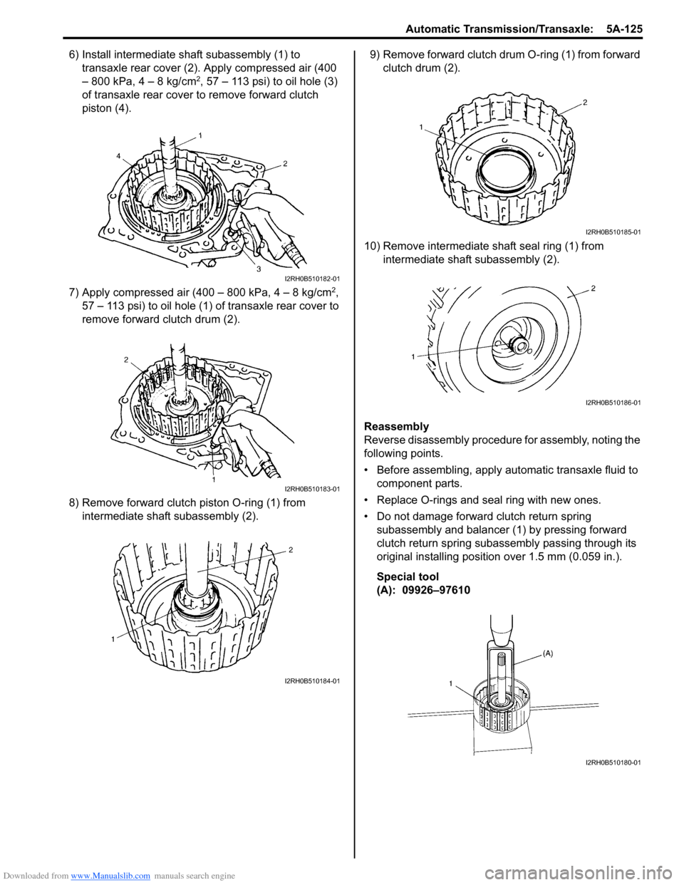
6) Install intermediate shaft subassembly (1) to
transaxle rear cover (2). Apply compressed air (400
– 800 kPa, 4 – 8 kg/cm
2, 57 – 113 psi) to oil hole (3)
of transaxle rear cover to remove forward clutch
piston (4).
7) Apply compressed air (400 – 800 kPa, 4 – 8 kg/cm
2,
57 – 113 psi) to oil hole (1) of transaxle rear cover to
remove forward clutch drum (2).
8) Remove forward clutch piston O-ring (1) from
intermediate shaft subassembly (2).9) Remove forward clutch drum O-ring (1) from forward
clutch drum (2).
10) Remove intermediate shaft seal ring (1) from
intermediate shaft subassembly (2).
Reassembly
Reverse disassembly procedure for assembly, noting the
following points.
• Before assembling, apply automatic transaxle fluid to
component parts.
• Replace O-rings and seal ring with new ones.
• Do not damage forward clutch return spring
subassembly and balancer (1) by pressing forward
clutch return spring subassembly passing through its
original installing position over 1.5 mm (0.059 in.).
Special tool
(A): 09926–97610
I2RH0B510182-01
I2RH0B510183-01
I2RH0B510184-01
I2RH0B510185-01
I2RH0B510186-01
I2RH0B510180-01
Page 776 of 1556
Downloaded from www.Manualslib.com manuals search engine 5A-128 Automatic Transmission/Transaxle:
Forward Clutch Piston Lip and Forward Clutch
Balancer Lip
Check each lip for wear, deformation, cut and/or
hardening. If necessary, replace.Forward Clutch Drum Lip
Check each lip for wear, deformation, cut and/or
hardening. If necessary, replace.
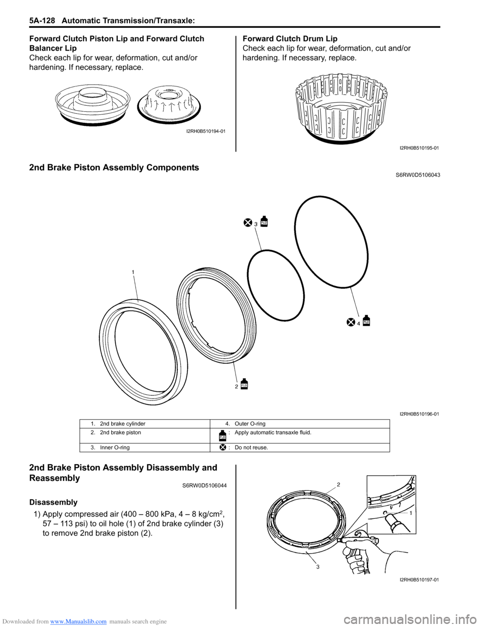
2nd Brake Piston Assembly ComponentsS6RW0D5106043
2nd Brake Piston Assembly Disassembly and
Reassembly
S6RW0D5106044
Disassembly
1) Apply compressed air (400 – 800 kPa, 4 – 8 kg/cm
2,
57 – 113 psi) to oil hole (1) of 2nd brake cylinder (3)
to remove 2nd brake piston (2).
I2RH0B510194-01
I2RH0B510195-01
I2RH0B510196-01
1. 2nd brake cylinder 4. Outer O-ring
2. 2nd brake piston : Apply automatic transaxle fluid.
3. Inner O-ring : Do not reuse.
I2RH0B510197-01
Page 778 of 1556
Downloaded from www.Manualslib.com manuals search engine 5A-130 Automatic Transmission/Transaxle:
Transaxle Rear Cover (O/D and 2nd Coast Brake
Piston) Assembly Disassembly and
Reassembly
S6RW0D5106046
Disassembly
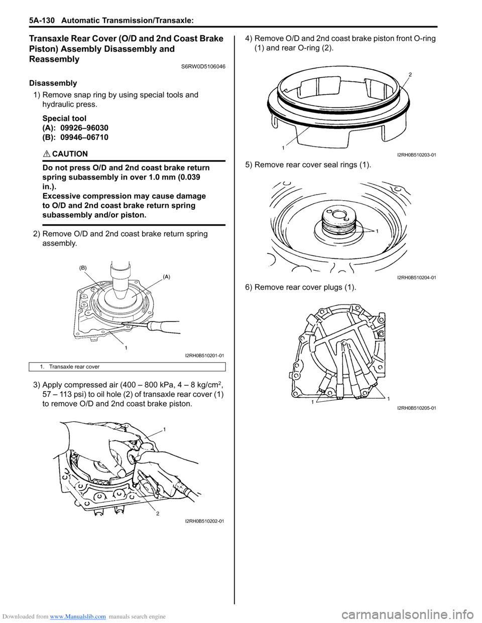
1) Remove snap ring by using special tools and
hydraulic press.
Special tool
(A): 09926–96030
(B): 09946–06710
CAUTION!
Do not press O/D and 2nd coast brake return
spring subassembly in over 1.0 mm (0.039
in.).
Excessive compression may cause damage
to O/D and 2nd coast brake return spring
subassembly and/or piston.
2) Remove O/D and 2nd coast brake return spring
assembly.
3) Apply compressed air (400 – 800 kPa, 4 – 8 kg/cm
2,
57 – 113 psi) to oil hole (2) of transaxle rear cover (1)
to remove O/D and 2nd coast brake piston.4) Remove O/D and 2nd coast brake piston front O-ring
(1) and rear O-ring (2).
5) Remove rear cover seal rings (1).
6) Remove rear cover plugs (1).
1. Transaxle rear cover
I2RH0B510201-01
I2RH0B510202-01
I2RH0B510203-01
I2RH0B510204-01
I2RH0B510205-01
Page 792 of 1556
Downloaded from www.Manualslib.com manuals search engine 5A-144 Automatic Transmission/Transaxle:
Automatic Transaxle Unit AssemblyS6RW0D5106058
CAUTION!
• Automatic transaxle consists of highly
precise parts. As even flaw in small part
may cause oil leakage or decrease in
function, check each part carefully before
installation.
• Clean all parts with compressed air. Never
use wiping cloths or rags.
• Before assembling new clutch or brake
discs, soak them in automatic transaxle
fluid for at least 2 hours.
• Be sure to use new gaskets and O-rings.
• Lubricate O-rings with automatic transaxle
fluid.
• Apply automatic transaxle fluid on sliding
or rotating surfaces of the parts before
assembly.
• Use Suzuki Super Grease “C” to retain
parts in place.
• Be sure to install thrust bearings and races
in correct direction and position.
• Make sure that snap ring ends are not
aligned with one of cutouts and are
installed in groove correctly.
• Do not use adhesive cements on gaskets
and similar parts.
• Be sure to torque each bolt and nut to
specification.
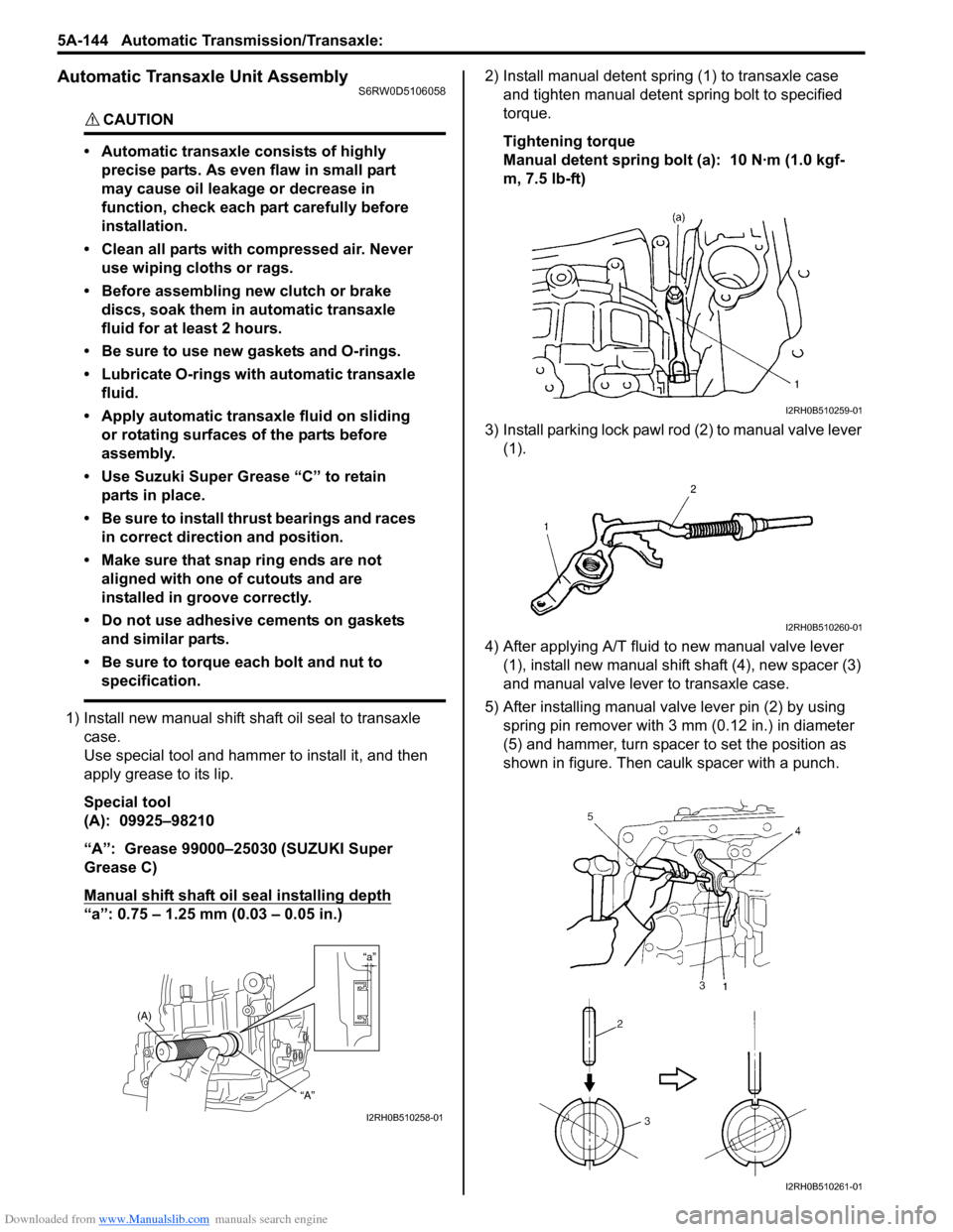
1) Install new manual shift shaft oil seal to transaxle
case.
Use special tool and hammer to install it, and then
apply grease to its lip.
Special tool
(A): 09925–98210
“A”: Grease 99000–25030 (SUZUKI Super
Grease C)
Manual shift shaft oil seal installing depth
“a”: 0.75 – 1.25 mm (0.03 – 0.05 in.)2) Install manual detent spring (1) to transaxle case
and tighten manual detent spring bolt to specified
torque.
Tightening torque
Manual detent spring bolt (a): 10 N·m (1.0 kgf-
m, 7.5 lb-ft)
3) Install parking lock pawl rod (2) to manual valve lever
(1).
4) After applying A/T fluid to new manual valve lever
(1), install new manual shift shaft (4), new spacer (3)
and manual valve lever to transaxle case.
5) After installing manual valve lever pin (2) by using
spring pin remover with 3 mm (0.12 in.) in diameter
(5) and hammer, turn spacer to set the position as
shown in figure. Then caulk spacer with a punch.
“a”
(A)
“A”
I2RH0B510258-01
I2RH0B510259-01
I2RH0B510260-01
I2RH0B510261-01
Page 794 of 1556
Downloaded from www.Manualslib.com manuals search engine 5A-146 Automatic Transmission/Transaxle:
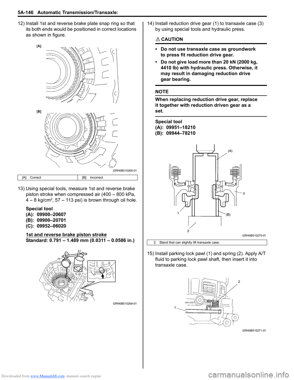
12) Install 1st and reverse brake plate snap ring so that
its both ends would be positioned in correct locations
as shown in figure.
13) Using special tools, measure 1st and reverse brake
piston stroke when compressed air (400 – 800 kPa,
4 – 8 kg/cm
2, 57 – 113 psi) is brown through oil hole.
Special tool
(A): 09900–20607
(B): 09900–20701
(C): 09952–06020
1st and reverse brake piston stroke
Standard: 0.791 – 1.489 mm (0.0311 – 0.0586 in.)14) Install reduction drive gear (1) to transaxle case (3)
by using special tools and hydraulic press.
CAUTION!
• Do not use transaxle case as groundwork
to press fit reduction drive gear.
• Do not give load more than 20 kN (2000 kg,
4410 lb) with hydraulic press. Otherwise, it
may result in damaging reduction drive
gear bearing.
NOTE
When replacing reduction drive gear, replace
it together with reduction driven gear as a
set.
Special tool
(A): 09951–18210
(B): 09944–78210
15) Install parking lock pawl (1) and spring (2). Apply A/T
fluid to parking lock pawl shaft, then insert it into
transaxle case.
[A]: Correct [B]: Incorrect
I2RH0B510268-01
I2RH0B510269-01
2. Stand that can slightly lift transaxle case.
I2RH0B510270-01
I2RH0B510271-01
Page 813 of 1556
Downloaded from www.Manualslib.com manuals search engine Manual Transmission/Transaxle: 5B-1
Transmission / Transaxle
Manual Transmission/Transaxle
General Description
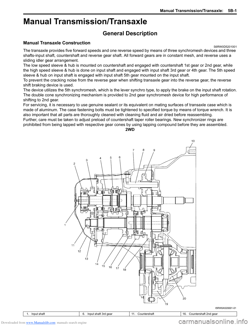
Manual Transaxle ConstructionS6RW0D5201001
The transaxle provides five forward speeds and one reverse speed by means of three synchromesh devices and three
shafts-input shaft, countershaft and reverse gear shaft. All forward gears are in constant mesh, and reverse uses a
sliding idler gear arrangement.
The low speed sleeve & hub is mounted on countershaft and engaged with countershaft 1st gear or 2nd gear, while
the high speed sleeve & hub is done on input shaft and engaged with input shaft 3rd gear or 4th gear. The 5th speed
sleeve & hub on input shaft is engaged with input shaft 5th gear mounted on the input shaft.
To prevent the cracking noise from the reverse gear when shifting transaxle gear into the reverse gear, the reverse
shift braking device is used.
The device utilizes the 5th synchromesh, which is the lever synchro type, to apply the brake on the input shaft rotation.
The double cone synchronizing mechanism is provided to 2nd gear synchromesh device for high performance of
shifting to 2nd gear.
For servicing, it is necessary to use genuine sealant or its equivalent on mating surfaces of transaxle case which is
made of aluminum. The case fastening bolts must be tightened to specified torque by means of torque wrench. It is
also important that all parts are thoroughly cleaned with cleaning fluid and air dried before reassembling.
Further, care must be taken to adjust preload of countershaft taper roller bearings. New synchronizer rings are
prohibited from being lapped with respective gear cones by using lapping compound before they are assembled.
2WD
I5RW0A520001-01
1. Input shaft 6. Input shaft 3rd gear 11. Countershaft 16. Countershaft 2nd gear
Page 817 of 1556

Downloaded from www.Manualslib.com manuals search engine Manual Transmission/Transaxle: 5B-5
Diagnostic Information and Procedures
Manual Transaxle Symptom DiagnosisS6RW0D5204001
Repair Instructions
Manual Transaxle Oil Level CheckS6RW0D5206001
1) Lift up vehicle and check oil leakage. Repair leaky
point, if any.
2) Remove oil level / filler plug (1) and check oil
contamination and oil level is lower end of oil level /
filler plug hole (2).
If oil is excessive dirty or insufficient, replace oil or
pour specified oil up to plug hole.
3) Apply sealant to thread of level / filler plug, and then
tighten it to specified torque.
“A”: Sealant 99000–31260 (SUZUKI Bond
No.1217G)
Tightening torque
Transaxle oil level / filler plug (a): 21 N·m (2.1
kgf-m, 15.5 lb-ft)Condition Possible cause Correction / Reference Item
Gears slipping out of
meshWorn shift fork shaftReplace
Worn shift fork or synchronizer sleeveReplace
Weak or damaged locating springsReplace
Worn bearings on input shaft or
countershaftReplace
Worn chamfered tooth on sleeve and
gearReplace sleeve and gear
Hard shiftingInadequate lubricantReplenish
Improper clutch pedal free travelReplace clutch arm or master cylinder
Distorted or broken clutch discReplace
Damaged clutch pressure plateReplace clutch cover
Worn synchronizer ringReplace
Worn chamfered tooth on sleeve or gearReplace sleeve or gear
Worn gear shift control shaft joint bushReplace
Distorted shift shaftReplace
Broken gear shift / select control cablesReplace
NoiseInadequate or insufficient lubricantReplenish
Damaged or worn bearing(s)Replace
Damaged or worn gear(s)Replace
Damaged or worn synchronizer partsReplace
I5RW0A520004-01