oil change SUZUKI SX4 2006 1.G Service Owner's Guide
[x] Cancel search | Manufacturer: SUZUKI, Model Year: 2006, Model line: SX4, Model: SUZUKI SX4 2006 1.GPages: 1556, PDF Size: 37.31 MB
Page 551 of 1556
Downloaded from www.Manualslib.com manuals search engine Transfer: 3C-4
• Pour transaxle oil and transfer oil referring to “Manual
Transaxle Oil Change in Section 5B” and “Transfer Oil
Change”.
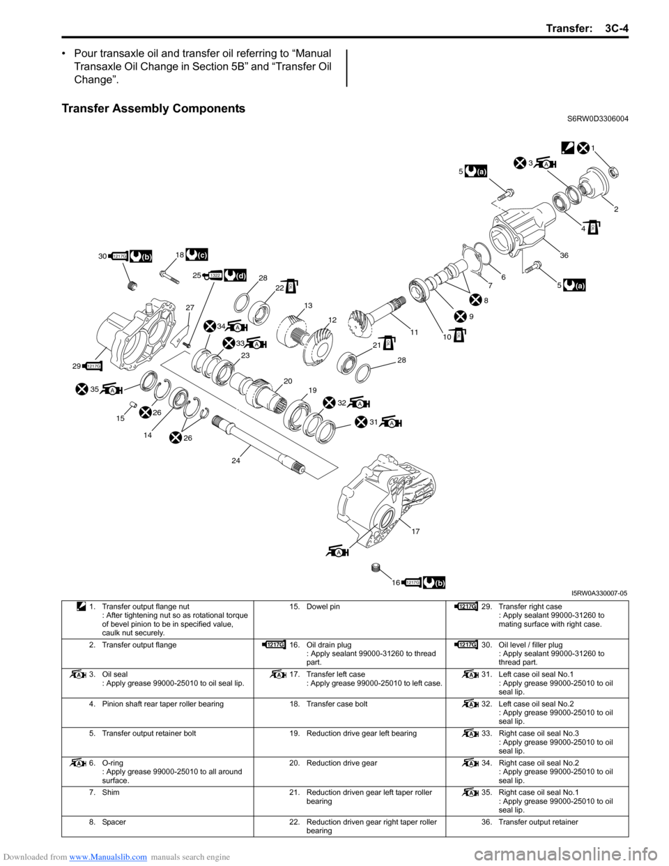
Transfer Assembly ComponentsS6RW0D3306004
1
2
6
9
1110
8
7
3A
4
5
36
OIL
(a) 5
(a)
OIL
28
18
30
27
25
21
28
13
12
22OIL
OIL
32A
31A
1322(d)
34A
33
23A
2019
(c)1217G
291217G
(b)
35
15A
26
26 14
24
17
161217G(b)
A
I5RW0A330007-05
1. Transfer output flange nut
: After tightening nut so as rotational torque
of bevel pinion to be in specified value,
caulk nut securely.15. Dowel pin 29. Transfer right case
: Apply sealant 99000-31260 to
mating surface with right case.
2. Transfer output flange 16. Oil drain plug
: Apply sealant 99000-31260 to thread
part.30. Oil level / filler plug
: Apply sealant 99000-31260 to
thread part.
3. Oil seal
: Apply grease 99000-25010 to oil seal lip.17. Transfer left case
: Apply grease 99000-25010 to left case.31. Left case oil seal No.1
: Apply grease 99000-25010 to oil
seal lip.
4. Pinion shaft rear taper roller bearing 18. Transfer case bolt 32. Left case oil seal No.2
: Apply grease 99000-25010 to oil
seal lip.
5. Transfer output retainer bolt 19. Reduction drive gear left bearing 33. Right case oil seal No.3
: Apply grease 99000-25010 to oil
seal lip.
6. O-ring
: Apply grease 99000-25010 to all around
surface.20. Reduction drive gear 34. Right case oil seal No.2
: Apply grease 99000-25010 to oil
seal lip.
7. Shim 21. Reduction driven gear left taper roller
bearing35. Right case oil seal No.1
: Apply grease 99000-25010 to oil
seal lip.
8. Spacer 22. Reduction driven gear right taper roller
bearing36. Transfer output retainer
Page 646 of 1556
Downloaded from www.Manualslib.com manuals search engine 5-ii Table of Contents
DTC P1723: Range Select Switch
Malfunction ...................................................... 5A-68
DTC P1878: Torque Converter Clutch
Shudder .......................................................... 5A-69
DTC P2762: Torque Converter Clutch (TCC)
Pressure Control Solenoid Control Circuit
Range / Performance ...................................... 5A-70
DTC P2763: Torque Converter Clutch (TCC)
Pressure Control Solenoid Control Circuit
High ................................................................. 5A-72
DTC P2764: Torque Converter Clutch (TCC)
Circuit Pressure Control Solenoid Control
Circuit Low ...................................................... 5A-74
DTC U0073: Control Module Communication
Bus Off ............................................................ 5A-76
DTC U0100: Lost Communication with ECM /
PCM “A” .......................................................... 5A-76
Inspection of TCM and Its Circuits .................... 5A-76
TCM Power and Ground Circuit Check ............. 5A-80
Brake Interlock System Inspection .................... 5A-81
Repair Instructions ............................................5A-82
Learning Control Initialization ............................ 5A-82
A/T Fluid Level Check ....................................... 5A-82
A/T Fluid Change .............................................. 5A-83
Select Lever Components ................................. 5A-84
Select Lever Assembly Removal and
Installation ....................................................... 5A-84
Select Lever Knob Installation........................... 5A-84
Select Lever Inspection ..................................... 5A-85
“3” Position Switch Inspection ........................... 5A-85
Shift Lock Solenoid Inspection .......................... 5A-85
Shift Lock Solenoid Replacement ..................... 5A-85
Select Cable Components ................................ 5A-86
Select Cable Removal and Installation ............. 5A-86
Select Cable Adjustment ................................... 5A-86
Key Interlock Cable Removal and Installation... 5A-87
Transmission Range Sensor Inspection and
Adjustment ...................................................... 5A-89
Output Shaft Speed Sensor (VSS) Removal
and Installation ................................................ 5A-90
Output Shaft Speed Sensor (VSS) Inspection .. 5A-90
Input Shaft Speed Sensor Removal and
Installation ....................................................... 5A-91
Input Shaft Speed Sensor Inspection................ 5A-91
Transmission Fluid Temperature Sensor
Removal and Installation ................................. 5A-91
Transmission Fluid Temperature Sensor
Inspection ........................................................ 5A-92
Solenoid Valves (Shift Solenoid Valves and
Timing Solenoid Valve) Removal and
Installation ....................................................... 5A-92
Solenoid Valves (Shift Solenoid Valves and
Timing Solenoid Valve) Inspection .................. 5A-94
Pressure Control Solenoid Valves (Pressure
Control Solenoid and TCC Solenoid)
Removal and Installation ................................. 5A-95
Pressure Control Solenoid Valves Inspection ... 5A-96
Transmission Control Module (TCM)
Removal and Installation ................................. 5A-97
A/T Relay Inspection ......................................... 5A-97Differential Side Oil Seal Replacement ............. 5A-98
A/T Fluid Cooler Hoses Replacement ............... 5A-98
Automatic Transaxle Unit Components............. 5A-99
Automatic Transaxle Unit Dismounting and
Remounting ................................................... 5A-100
Automatic Transaxle Assembly Components . 5A-102
Automatic Transaxle Unit Disassembly........... 5A-104
Oil Pump Assembly Components ................... 5A-116
Oil Pump Assembly Disassembly and
Reassembly .................................................. 5A-116
Oil Pump Assembly Inspection ....................... 5A-117
Direct Clutch Assembly Components.............. 5A-119
Direct Clutch Assembly Preliminary Check ..... 5A-119
Direct Clutch Assembly Disassembly and
Reassembly .................................................. 5A-120
Direct Clutch Assembly Inspection.................. 5A-122
Forward and Reverse Clutch Assembly
Components .................................................. 5A-123
Forward and Reverse Clutch Assembly
Preliminary Check ......................................... 5A-123
Forward and Reverse Clutch Assembly
Disassembly and Reassembly ...................... 5A-124
Forward and Reverse Clutch Assembly
Inspection ...................................................... 5A-127
2nd Brake Piston Assembly Components ....... 5A-128
2nd Brake Piston Assembly Disassembly and
Reassembly .................................................. 5A-128
Transaxle Rear Cover (O/D and 2nd Coast
Brake Piston) Assembly Components........... 5A-129
Transaxle Rear Cover (O/D and 2nd Coast
Brake Piston) Assembly Disassembly and
Reassembly .................................................. 5A-130
Transaxle Rear Cover (O/D and 2nd Coast
Brake Piston) Assembly Inspection............... 5A-131
Countershaft Assembly Components.............. 5A-132
Countershaft Assembly Disassembly and
Reassembly .................................................. 5A-132
Valve Body Assembly Components ................ 5A-133
Valve Body Assembly Disassembly and
Reassembly .................................................. 5A-134
Differential Assembly Components ................. 5A-135
Differential Assembly Disassembly and
Reassembly .................................................. 5A-136
Differential Assembly Inspection ..................... 5A-137
Torque Converter Housing Disassembly and
Reassembly .................................................. 5A-138
Transaxle Case Disassembly and
Reassembly .................................................. 5A-140
Automatic Transaxle Unit Inspection and
Adjustment .................................................... 5A-141
Automatic Transaxle Unit Assembly ............... 5A-144
Specifications ...................................................5A-161
Tightening Torque Specifications .................... 5A-161
Special Tools and Equipment .........................5A-162
Recommended Service Material ..................... 5A-162
Special Tool .................................................... 5A-162
Manual Transmission/Transaxle ............ 5B-1
General Description .............................................5B-1
Manual Transaxle Construction .......................... 5B-1
Page 647 of 1556

Downloaded from www.Manualslib.com manuals search engine Table of Contents 5-iii
Diagnostic Information and Procedures ............ 5B-5
Manual Transaxle Symptom Diagnosis............... 5B-5
Repair Instructions .............................................. 5B-5
Manual Transaxle Oil Level Check ..................... 5B-5
Manual Transaxle Oil Change ............................ 5B-6
Differential Side Oil Seal Replacement ............... 5B-7
Gear Shift Control Lever and Cable
Components...................................................... 5B-8
Gear Shift Control Lever and Cable Removal
and Installation .................................................. 5B-9
Gear Select Control Cable Adjustment ............... 5B-9
Back Up Light Switch Removal and
Installation ....................................................... 5B-10
Back Up Light Switch Inspection ....................... 5B-10
Manual Transaxle Unit Components ................. 5B-11
Manual Transaxle Unit Dismounting and
Remounting..................................................... 5B-12
Gear Shift and Select Shaft Assembly
Components.................................................... 5B-13
Gear Shift and Select Shaft Assembly
Removal and Installation................................. 5B-14
Gear Shift and Select Shaft Assembly
Disassembly and Reassembly ........................ 5B-15
Manual Transaxle Assembly Components........ 5B-16
Fifth Gear Disassembly and Reassembly ......... 5B-17
Manual Transaxle Assembly Disassembly
and Reassembly ............................................. 5B-19
Right Case Disassembly and Reassembly ....... 5B-24
Left Case Disassembly and Reassembly.......... 5B-25
Input Shaft and Countershaft Components....... 5B-27
Input Shaft Disassembly and Reassembly........ 5B-28
Countershaft Disassembly and Reassembly .... 5B-31
Gear Shift Shaft Components ........................... 5B-35
5th and Reverse Gear Shift Shafts
Disassembly and Reassembly ........................ 5B-35
Gear Shift Shaft and Fork Inspection ................ 5B-35
Differential Components ................................... 5B-36Differential Disassembly and Reassembly ........ 5B-36
Specifications .....................................................5B-38
Tightening Torque Specifications ...................... 5B-38
Special Tools and Equipment ...........................5B-39
Recommended Service Material ....................... 5B-39
Special Tool ...................................................... 5B-39
Clutch ....................................................... 5C-1
General Description .............................................5C-1
Clutch (Hydraulic Type) Construction .................5C-1
Diagnostic Information and Procedures ............5C-2
Clutch System Symptom Diagnosis ....................5C-2
Repair Instructions ..............................................5C-3
Clutch Pedal Inspection ......................................5C-3
Clutch Fluid Level Inspection ..............................5C-3
Air Bleeding of Clutch System.............................5C-3
Clutch Fluid Pipe and Hose Location ..................5C-4
Clutch Fluid Pipe Removal and Installation.........5C-4
Clutch Fluid Pipe Inspection................................5C-4
Clutch Master Cylinder Removal and
Installation .........................................................5C-5
Clutch Operating Cylinder Assembly
Removal and Installation ...................................5C-5
Clutch Operating Cylinder Assembly
Inspection ..........................................................5C-6
Clutch Cover, Clutch Disc and Flywheel
Components ......................................................5C-6
Clutch Cover, Clutch Disc and Flywheel
Removal and Installation ...................................5C-7
Clutch Cover, Clutch Disc and Flywheel
Inspection ..........................................................5C-8
Specifications .......................................................5C-9
Tightening Torque Specifications ........................5C-9
Special Tools and Equipment ...........................5C-10
Recommended Service Material .......................5C-10
Special Tool ......................................................5C-10
Page 653 of 1556
Downloaded from www.Manualslib.com manuals search engine Automatic Transmission/Transaxle: 5A-5
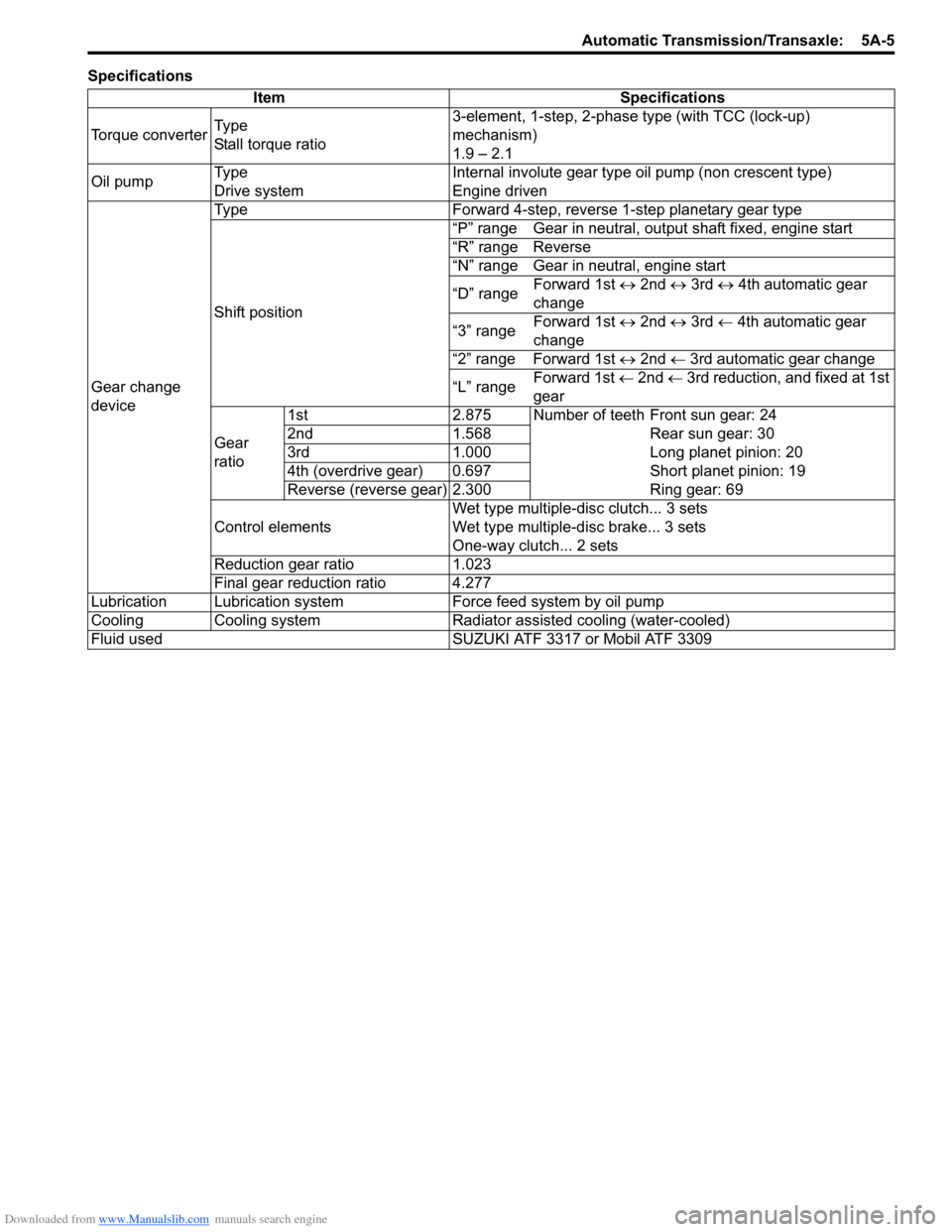
Specifications
Item Specifications
Torque converterTy p e
Stall torque ratio3-element, 1-step, 2-phase type (with TCC (lock-up)
mechanism)
1.9 – 2.1
Oil pumpTy p e
Drive systemInternal involute gear type oil pump (non crescent type)
Engine driven
Gear change
deviceType Forward 4-step, reverse 1-step planetary gear type
Shift position“P” range Gear in neutral, output shaft fixed, engine start
“R” range Reverse
“N” range Gear in neutral, engine start
“D” range Forward 1st ↔ 2nd ↔ 3rd ↔ 4th automatic gear
change
“3” rangeForward 1st ↔ 2nd ↔ 3rd ← 4th automatic gear
change
“2” range Forward 1st ↔ 2nd ← 3rd automatic gear change
“L” rangeForward 1st ← 2nd ← 3rd reduction, and fixed at 1st
gear
Gear
ratio1st 2.875 Number of teeth Front sun gear: 24
2nd 1.568 Rear sun gear: 30
3rd 1.000 Long planet pinion: 20
4th (overdrive gear) 0.697 Short planet pinion: 19
Reverse (reverse gear) 2.300 Ring gear: 69
Control elementsWet type multiple-disc clutch... 3 sets
Wet type multiple-disc brake... 3 sets
One-way clutch... 2 sets
Reduction gear ratio 1.023
Final gear reduction ratio 4.277
Lubrication Lubrication system Force feed system by oil pump
Cooling Cooling system Radiator assisted cooling (water-cooled)
Fluid used SUZUKI ATF 3317 or Mobil ATF 3309
Page 666 of 1556
Downloaded from www.Manualslib.com manuals search engine 5A-18 Automatic Transmission/Transaxle:
Step 2. DTC / Freeze Frame Data Check, Record and
Clearance
First, referring to “DTC Check”, check DTC and pending
DTC. If DTC exists, print or write down DTC and freeze
frame data and then clear malfunction DTC(s) by
referring to “DTC Clearance”. Malfunction DTC indicates
malfunction in the system but it is not possible to know
from it whether the malfunction is occurring now or it
occurred in the past and normal condition has been
restored. In order to know that, check symptom in
question according to Step 5 and then recheck DTC
according to Step 6.
Diagnosing a trouble based on the DTC in this step only
or failure to clear the DTC in this step may result in an
faulty diagnosis, trouble diagnosis of a normal circuit or
difficulty in troubleshooting which is otherwise
unnecessary.
Step 3 and 4. Visual Inspection
As a preliminary step, be sure to perform visual check of
the items that support proper function of the engine and
automatic transaxle referring to “Visual Inspection”.
Step 5. Trouble Symptom Confirmation
Check trouble symptoms based on information obtained
in “Step 1. Customer Complaint Analysis: ” and “Step 2.
DTC / Freeze Frame Data Check, Record and
Clearance: ”.
Also, reconfirm DTC according to “DTC Confirmation
Procedure” described in each DTC flow.
Step 6 and 7. Rechecking and Record of DTC and
Freeze Frame Data
Refer to “DTC Check” for checking procedure.Step 8. A/T Basic Check and A/T Symptom
Diagnosis
Perform basic check of A/T according to “A/T Basic
Check” first. When the end of the flow has been reached,
check the parts of the system suspected as a possible
cause referring to “A/T Symptom Diagnosis” and based
on symptoms appearing on the vehicle (symptoms
obtained through steps of customer complaint analysis,
trouble symptom confirmation and/or A/T basic check)
and repair or replace faulty parts, if any.
Step 9. Troubleshooting for DTC
Based on the DTC indicated in Step 6 / 7 and referring to
“applicable DTC flow”, locate the cause of the trouble,
namely in a sensor, switch, wire harness, connector,
actuator, TCM or other part and repair or replace faulty
parts.
Step 10. Check for Intermittent Problem
Check parts where an intermittent trouble is easy to
occur (e.g. wire harness, connector, etc.), referring to
“Intermittent and Poor Connection Inspection in Section
00” and related circuit of DTC recorded in Step 2.
Step 11. Final Confirmation Test
Confirm that the problem symptom has gone and the
vehicle is free from any abnormal conditions. If what has
been repaired is related to the malfunction DTC, clear
the DTC once and check to ensure that no malfunction
DTC is indicated.
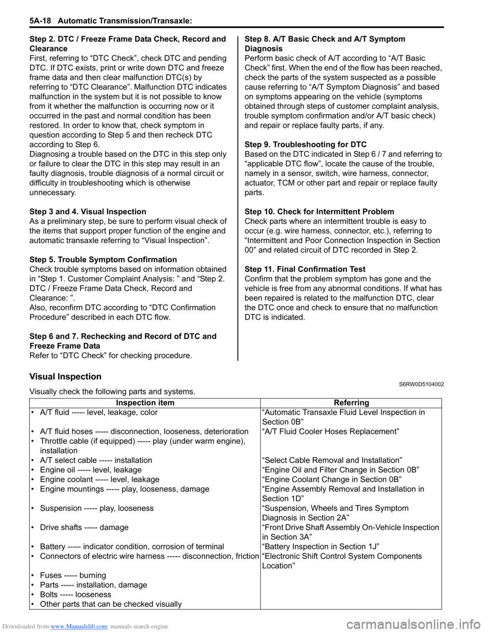
Visual InspectionS6RW0D5104002
Visually check the following parts and systems.
Inspection item Referring
• A/T fluid ----- level, leakage, color “Automatic Transaxle Fluid Level Inspection in
Section 0B”
• A/T fluid hoses ----- disconnection, looseness, deterioration “A/T Fluid Cooler Hoses Replacement”
• Throttle cable (if equipped) ----- play (under warm engine),
installation
• A/T select cable ----- installation “Select Cable Removal and Installation”
• Engine oil ----- level, leakage “Engine Oil and Filter Change in Section 0B”
• Engine coolant ----- level, leakage “Engine Coolant Change in Section 0B”
• Engine mountings ----- play, looseness, damage “Engine Assembly Removal and Installation in
Section 1D”
• Suspension ----- play, looseness “Suspension, Wheels and Tires Symptom
Diagnosis in Section 2A”
• Drive shafts ----- damage “Front Drive Shaft Assembly On-Vehicle Inspection
in Section 3A”
• Battery ----- indicator condition, corrosion of terminal “Battery Inspection in Section 1J”
• Connectors of electric wire harness ----- disconnection, friction “Electronic Shift Control System Components
Location”
• Fuses ----- burning
• Parts ----- installation, damage
• Bolts ----- looseness
• Other parts that can be checked visually
Page 731 of 1556
Downloaded from www.Manualslib.com manuals search engine Automatic Transmission/Transaxle: 5A-83
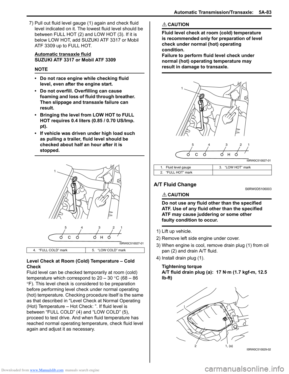
7) Pull out fluid level gauge (1) again and check fluid
level indicated on it. The lowest fluid level should be
between FULL HOT (2) and LOW HOT (3). If it is
below LOW HOT, add SUZUKI ATF 3317 or Mobil
ATF 3309 up to FULL HOT.
Automatic transaxle fluid
SUZUKI ATF 3317 or Mobil ATF 3309
NOTE
• Do not race engine while checking fluid
level, even after the engine start.
• Do not overfill. Overfilling can cause
foaming and loss of fluid through breather.
Then slippage and transaxle failure can
result.
• Bringing the level from LOW HOT to FULL
HOT requires 0.4 liters (0.85 / 0.70 US/Imp.
pt).
• If vehicle was driven under high load such
as pulling a trailer, fluid level should be
checked about half an hour after it is
stopped.
Level Check at Room (Cold) Temperature – Cold
Check
Fluid level can be checked temporarily at room (cold)
temperature which correspond to 20 – 30 °C (68 – 86
°F). This level check is considered to be preparation
before performing level check under normal operating
(hot) temperature. Checking procedure itself is the same
as that described in “Level Check at Normal Operating
(Hot) Temperature – Hot Check: ”. If fluid level is
between “FULL COLD” (4) and “LOW COLD” (5),
proceed to test drive. And when fluid temperature has
reached normal operating temperature, check fluid level
again and adjust it as necessary.
CAUTION!
Fluid level check at room (cold) temperature
is recommended only for preparation of level
check under normal (hot) operating
condition.
Failure to perform fluid level check under
normal (hot) operating temperature may
result in damage to transaxle.
A/T Fluid ChangeS6RW0D5106003
CAUTION!
Do not use any fluid other than the specified
ATF. Use of any fluid other than the specified
ATF may cause juddering or some other
faulty condition to occur.
1) Lift up vehicle.
2) Remove left side engine under cover.
3) When engine is cool, remove drain plug (1) from oil
pan (2) and drain A/T fluid.
4) Install drain plug (1).
Tightening torque
A/T fluid drain plug (a): 17 N·m (1.7 kgf-m, 12.5
lb-ft)
4. “FULL COLD” mark 5. “LOW COLD” mark
1
54 321
I5RW0C510027-01
1. Fluid level gauge 3. “LOW HOT” mark
2. “FULL HOT” mark
1
54 321
I5RW0C510027-01
21, (a)I5RW0C510029-02
Page 739 of 1556

Downloaded from www.Manualslib.com manuals search engine Automatic Transmission/Transaxle: 5A-91
Input Shaft Speed Sensor Removal and
Installation
S6RW0D5106012
Removal
1) Disconnect negative cable at battery.
2) Disconnect input shaft speed sensor connector (2).
3) Remove input shaft speed sensor (1) by removing its
bolt.
Installation
1) Apply A/T fluid to input shaft speed sensor O-ring.
2) Install input shaft speed sensor (1) to A/T case and
tighten bolt to specified torque.
Tightening torque
Input shaft speed sensor bolt (a): 5.5 N·m (0.55
kgf-m, 4.0 lb-ft)
3) Connect input shaft speed sensor connector (2) to
input shaft speed sensor (1).
4) Connect negative cable to battery.
Input Shaft Speed Sensor InspectionS6RW0D5106013
1) Disconnect negative cable at battery.
2) Disconnect input shaft speed sensor connector (2).
3) Check resistance between input shaft speed sensor
(1) terminals.
Input shaft speed sensor resistance
Standard: 560 – 680 Ω at 20 °C (68 °F)
Transmission Fluid Temperature Sensor
Removal and Installation
S6RW0D5106014
Removal
1) Disconnect negative cable at battery.
2) Lift up vehicle.
3) Remove left side engine under cover.
4) With engine is cool, remove drain plug and drain A/T
fluid.
5) Install drain plug. Refer to “A/T Fluid Change”.
6) Remove A/T oil pan.
7) Remove oil strainer assembly.
8) Remove valve body assembly referring to
“Automatic Transaxle Unit Disassembly”.
CAUTION!
When pulling valve body harness out of
transaxle case, take care not to damage
transmission fluid temperature sensor at
narrow exit of case.
Careless sensor treatment might cause
sensor malfunction.
9) Remove valve body harness (1).
12
I5RW0C510034-01
12
(a)I5RW0C510035-01
12I5RW0C510036-01
I2RH0B510050-01
Page 740 of 1556

Downloaded from www.Manualslib.com manuals search engine 5A-92 Automatic Transmission/Transaxle:
Installation
Reverse removal procedure to install valve body
harness and valve body assembly noting the following
points.
• For details of valve body assembly and their
connectors installation, refer to “Automatic Transaxle
Unit Assembly”.
• For details of A/T oil pan installation, refer to
“Automatic Transaxle Unit Assembly”. Use new oil
pan gasket.
• Tighten valve body harness connector bolt to
specified torque.
Tightening torque
Valve body harness connector bolt (a): 5.5 N·m (
0.55 kgf-m, 4.0 lb-ft)
• Pour A/T fluid and check fluid level according to
procedure described in “A/T Fluid Change”.
• Check for fluid leakage after warming up A/T.Transmission Fluid Temperature Sensor
Inspection
S6RW0D5106015
Warm up transmission fluid temperature sensor (2).
Check resistance between terminals of valve body
harness connector (1). Thus make sure its resistance
decrease as its temperature increase.
Transmission fluid temperature sensor resistance
10 °C (50 °F): 5.8 – 7.1 kΩ
11 0 °C (230 °F): 231 – 263 Ω
145 °C (293 °F): 105 – 117 Ω
Solenoid Valves (Shift Solenoid Valves and
Timing Solenoid Valve) Removal and
Installation
S6RW0D5106061
Removal
1) Disconnect negative cable at battery.
2) Lift up vehicle.
3) Remove left side engine under cover.
4) Remove drain plug and drain A/T fluid.
5) Install drain plug.
Tightening torque
A/T fluid drain plug: 17 N·m (1.7 kgf-m, 12.5 lb-ft)
6) Remove A/T oil pan (1) and oil pan gasket (2).
I2RH0B510051-01
I2RH0B510052-01
Page 744 of 1556
Downloaded from www.Manualslib.com manuals search engine 5A-96 Automatic Transmission/Transaxle:
10) Remove valve body assembly referring to
“Automatic Transaxle Unit Disassembly”.
11) Remove pressure control solenoid valve and TCC
pressure control solenoid valve referring to “Valve
Body Assembly Disassembly and Reassembly”.
Installation
Reverse removal procedure to install pressure control
solenoid valve and valve body assembly noting the
following points.
• For detail of pressure control solenoid valve and TCC
pressure control solenoid valve installation, refer to
“Valve Body Assembly Disassembly and
Reassembly”.
• For detail of valve body assembly installation, refer to
“Automatic Transaxle Unit Assembly”.
• For detail of installing wire harness for solenoid valves
and sensor, refer to “Automatic Transaxle Unit
Assembly”. Use new O-rings.
• For detail of A/T oil pan and oil strainer assembly
installation, refer to “Automatic Transaxle Unit
Assembly”. Use new oil pan gasket.
• Pour A/T fluid and check fluid level according to
procedure described in “A/T Fluid Change”.
• Check for fluid leakage after warming up A/T.
Pressure Control Solenoid Valves InspectionS6RW0D5106020
CAUTION!
• Be very careful as dust etc. does enter
when pressure control solenoid valves are
inspected.
Resistance Check
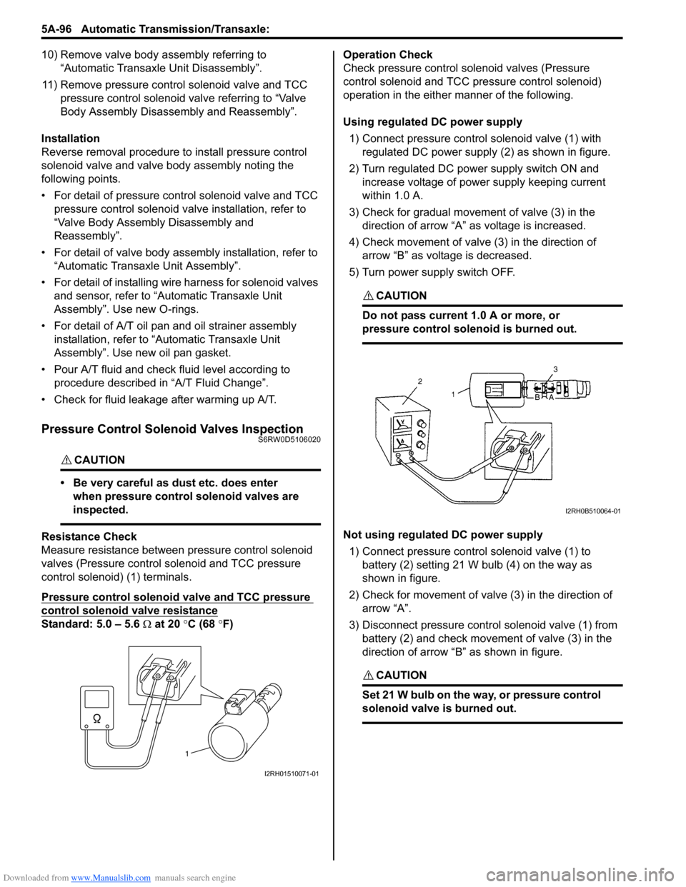
Measure resistance between pressure control solenoid
valves (Pressure control solenoid and TCC pressure
control solenoid) (1) terminals.
Pressure control solenoid valve and TCC pressure
control solenoid valve resistance
Standard: 5.0 – 5.6 Ω at 20 °C (68 °F)Operation Check
Check pressure control solenoid valves (Pressure
control solenoid and TCC pressure control solenoid)
operation in the either manner of the following.
Using regulated DC power supply
1) Connect pressure control solenoid valve (1) with
regulated DC power supply (2) as shown in figure.
2) Turn regulated DC power supply switch ON and
increase voltage of power supply keeping current
within 1.0 A.
3) Check for gradual movement of valve (3) in the
direction of arrow “A” as voltage is increased.
4) Check movement of valve (3) in the direction of
arrow “B” as voltage is decreased.
5) Turn power supply switch OFF.
CAUTION!
Do not pass current 1.0 A or more, or
pressure control solenoid is burned out.
Not using regulated DC power supply
1) Connect pressure control solenoid valve (1) to
battery (2) setting 21 W bulb (4) on the way as
shown in figure.
2) Check for movement of valve (3) in the direction of
arrow “A”.
3) Disconnect pressure control solenoid valve (1) from
battery (2) and check movement of valve (3) in the
direction of arrow “B” as shown in figure.
CAUTION!
Set 21 W bulb on the way, or pressure control
solenoid valve is burned out.
1
I2RH01510071-01
I2RH0B510064-01
Page 746 of 1556
Downloaded from www.Manualslib.com manuals search engine 5A-98 Automatic Transmission/Transaxle:
Differential Side Oil Seal ReplacementS6RW0D5106023
1) Lift up vehicle and drain automatic transaxle fluid.
2) Remove drive shaft assembly and center shaft
referring to “Front Drive Shaft Assembly Removal
and Installation in Section 3A”.
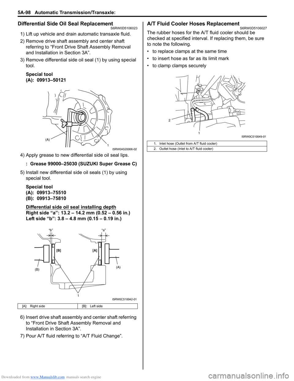
3) Remove differential side oil seal (1) by using special
tool.
Special tool
(A): 09913–50121
4) Apply grease to new differential side oil seal lips.
: Grease 99000–25030 (SUZUKI Super Grease C)
5) Install new differential side oil seals (1) by using
special tool.
Special tool
(A): 09913–75510
(B): 09913–75810
Differential side oil seal installing depth
Right side “a”: 13.2 – 14.2 mm (0.52 – 0.56 in.)
Left side “b”: 3.8 – 4.8 mm (0.15 – 0.19 in.)
6) Insert drive shaft assembly and center shaft referring
to “Front Drive Shaft Assembly Removal and
Installation in Section 3A”.
7) Pour A/T fluid referring to “A/T Fluid Change”.
A/T Fluid Cooler Hoses ReplacementS6RW0D5106027
The rubber hoses for the A/T fluid cooler should be
checked at specified interval. If replacing them, be sure
to note the following.
• to replace clamps at the same time
• to insert hose as far as its limit mark
• to clamp clamps securely
[A]: Right side [B]: Left side
(A)
1I5RW0A520006-02
“a” “b”
(B)[B] [A]
1
(A)
I5RW0C510042-01
1. Inlet hose (Outlet from A/T fluid cooler)
2. Outlet hose (Inlet to A/T fluid cooler)
2
1I5RW0C510049-01