Suspension SUZUKI SX4 2006 1.G Service Repair Manual
[x] Cancel search | Manufacturer: SUZUKI, Model Year: 2006, Model line: SX4, Model: SUZUKI SX4 2006 1.GPages: 1556, PDF Size: 37.31 MB
Page 469 of 1556
Downloaded from www.Manualslib.com manuals search engine Rear Suspension: 2C-10
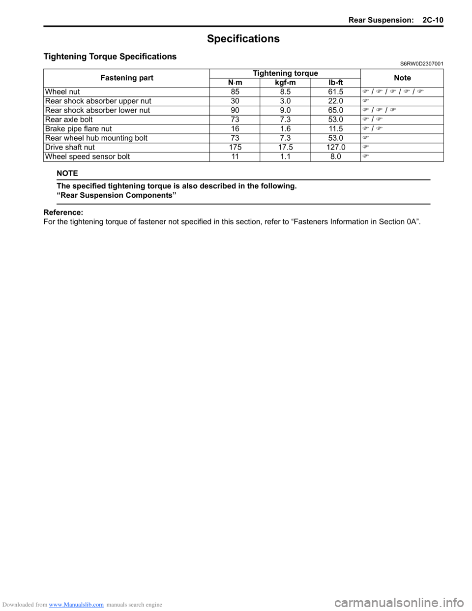
Specifications
Tightening Torque SpecificationsS6RW0D2307001
NOTE
The specified tightening torque is also described in the following.
“Rear Suspension Components”
Reference:
For the tightening torque of fastener not specified in this section, refer to “Fasteners Information in Section 0A”. Fastening partTightening torque
Note
N⋅mkgf-mlb-ft
Wheel nut 85 8.5 61.5) / ) / ) / ) / )
Rear shock absorber upper nut 30 3.0 22.0)
Rear shock absorber lower nut 90 9.0 65.0) / ) / )
Rear axle bolt 73 7.3 53.0) / )
Brake pipe flare nut 16 1.6 11.5) / )
Rear wheel hub mounting bolt 73 7.3 53.0)
Drive shaft nut 175 17.5 127.0)
Wheel speed sensor bolt 11 1.1 8.0)
Page 470 of 1556
Downloaded from www.Manualslib.com manuals search engine 2D-1 Wheels and Tires:
Suspension
Wheels and Tires
General Description
Tires DescriptionS6RW0D2401001
The tire is of tubeless type. The tire is designed to
operate satisfactorily with loads up to the full rated load
capacity when inflated to the recommended inflation
pressures.
Correct tire pressures and driving habits have an
important influence on tire life. Heavy cornering,
excessively rapid acceleration, and unnecessary sharp
braking increase tire wear.
Tire Placard
The “Tire Placard” is located on the left or right door lock
pillar and should be referred to tire information.
The placard lists the maximum load, tire size and cold
tire pressure where applicable.
NOTE
Whether rim size and/or maximum load are
listed or not depends on regulations of each
country.
Inflation of Tires
The pressure recommended for any model is carefully
calculated to give a satisfactory ride, stability, steering,
tread wear, tire life and resistance to bruises.
Tire pressure, with tires cold, (after vehicle has set for 3
hours or more, or driven less than one mile) should be
checked monthly or before any extended trip. Set to the
specifications on the “Tire Placard” located on the left or
right door lock pillar.
It is normal for tire pressure to increase when the tires
become hot during driving.
Do not bleed or reduce tire pressure after driving.
Bleeding reduces the “Cold Inflation Pressure”.
Higher than recommended pressure can cause:
• Hard ride
• Tire bruising or carcass damage
• Rapid tread wear at center of tire
Unequal pressure on same axle can cause:
• Uneven braking
• Steering lead
• Reduced handling
• Swerve on accelerationLower than recommended pressure can cause:
• Tire squeal on turns
• Hard Steering
• Rapid and uneven wear on the edges of the tread
• Tire rim bruises and rupture
• Tire cord breakage
• High tire temperature
• Reduced handling
• High fuel consumption
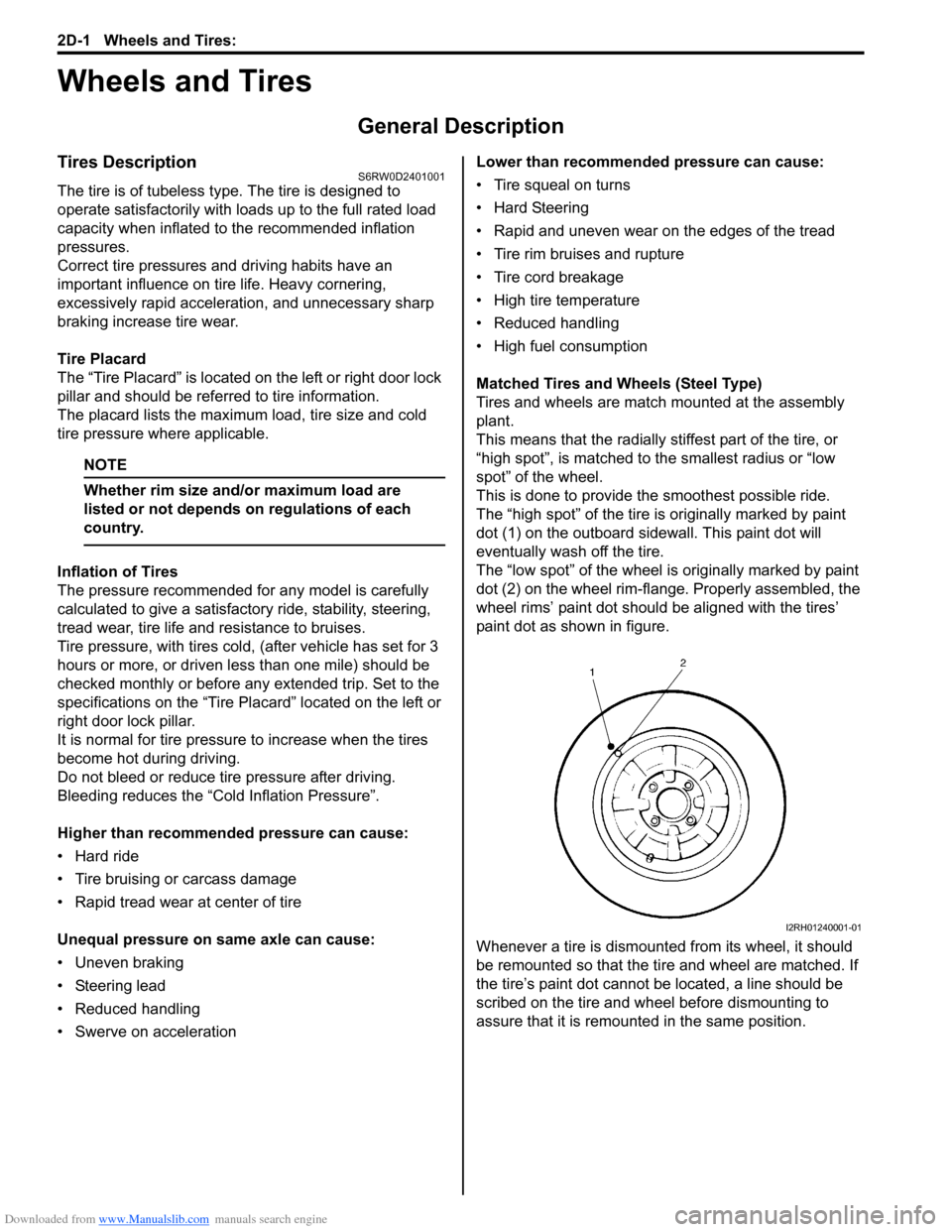
Matched Tires and Wheels (Steel Type)
Tires and wheels are match mounted at the assembly
plant.
This means that the radially stiffest part of the tire, or
“high spot”, is matched to the smallest radius or “low
spot” of the wheel.
This is done to provide the smoothest possible ride.
The “high spot” of the tire is originally marked by paint
dot (1) on the outboard sidewall. This paint dot will
eventually wash off the tire.
The “low spot” of the wheel is originally marked by paint
dot (2) on the wheel rim-flange. Properly assembled, the
wheel rims’ paint dot should be aligned with the tires’
paint dot as shown in figure.
Whenever a tire is dismounted from its wheel, it should
be remounted so that the tire and wheel are matched. If
the tire’s paint dot cannot be located, a line should be
scribed on the tire and wheel before dismounting to
assure that it is remounted in the same position.
I2RH01240001-01
Page 482 of 1556
Downloaded from www.Manualslib.com manuals search engine 3A-3 Drive Shaft / Axle: Front
Front Drive Shaft Assembly On-Vehicle
Inspection
S6RW0D3116002
• Check boots for breakage or deterioration.
• Check wheel side joint for rattle or smooth rotation.
• Check differential side (or center shaft side) joint for
smooth rotation.
If any abnormality is found, replace.
Front Drive Shaft Assembly Removal and
Installation
S6RW0D3116003
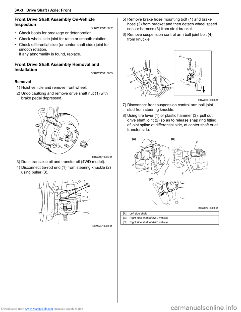
Removal
1) Hoist vehicle and remove front wheel.
2) Undo caulking and remove drive shaft nut (1) with
brake pedal depressed.
3) Drain transaxle oil and transfer oil (4WD model).
4) Disconnect tie-rod end (1) from steering knuckle (2)
using puller (3).5) Remove brake hose mounting bolt (1) and brake
hose (2) from bracket and then detach wheel speed
sensor harness (3) from strut bracket.
6) Remove suspension control arm ball joint bolt (4)
from knuckle.
7) Disconnect front suspension control arm ball joint
stud from steering knuckle.
8) Using tire lever (1) or plastic hammer (3), pull out
drive shaft joint (2) so as to release snap ring fitting
of joint spline at differential side, at center shaft or at
transfer side.
I6RW0B310005-01
I3RM0A310003-01
[A]: Left side shaft
[B]: Right side shaft of 2WD vehicle
[C]: Right side shaft of 4WD vehicle
I6RW0D311003-01
I5RW0A311003-01
Page 550 of 1556
Downloaded from www.Manualslib.com manuals search engine 3C-3 Transfer:
Transfer Dismounting and RemountingS6RW0D3306003
Dismounting
1) Disconnect negative cable at battery.
2) Drain transaxle oil and transfer oil.
3) Remove drive shafts assembly referring to “Front
Drive Shaft Assembly Removal and Installation in
Section 3A”.
4) Remove exhaust No.1, No.2 and center pipes
referring to “Exhaust Pipe and Muffler Removal and
Installation in Section 1K”.
5) Remove suspension frame, engine front mounting
member and mounting member referring to “Front
Suspension Frame, Stabilizer Bar and/or Bushing
Removal and Installation in Section 2B” and “Engine
Assembly Removal and Installation in Section 1D”.
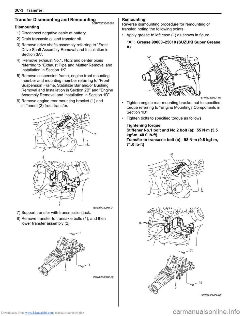
6) Remove engine rear mounting bracket (1) and
stiffeners (2) from transfer.
7) Support transfer with transmission jack.
8) Remove transfer to transaxle bolts (1), and then
lower transfer assembly (2).Remounting
Reverse dismounting procedure for remounting of
transfer, noting the following points.
• Apply grease to left case (1) as shown in figure.
“A”: Grease 99000–25010 (SUZUKI Super Grease
A)
• Tighten engine rear mounting bracket nut to specified
torque referring to “Engine Mountings Components in
Section 1D”.
• Tighten bolts to specified torque as follows.
Tightening torque
Stiffener No.1 bolt and No.2 bolt (a): 55 N·m (5.5
kgf-m, 40.0 lb-ft)
Transfer to transaxle bolt (b): 98 N·m (9.8 kgf-m,
71.0 lb-ft)
2
2
1I5RW0A330004-01
1
1
2
I5RW0A330005-02
I5RW0C330001-01
(a)
(a)
(b)
(b)
2
I5RW0A330006-02
Page 571 of 1556
Downloaded from www.Manualslib.com manuals search engine Precautions: 4-1
Brakes
Precautions
Precautions
Precautions for BrakesS6RW0D4000001
Suspension Caution
Refer to “Suspension Caution in Section 00”.
Wheels and Tires Caution
Refer to “Wheels and Tires Caution in Section 00”.
Brake Caution
Refer to “Brake Caution in Section 00”.
General Precautions
Refer to “General Precautions in Section 00”.
Vehicle Lifting Points
Refer to “Vehicle Lifting Points in Section 0A”.
Fastener Caution
Refer to “Fastener Caution in Section 00”.
Fastener Information
Refer to “Fasteners Information in Section 0A”.
Precaution on CAN Troubleshooting
Refer to “Precaution on CAN Troubleshooting in Section 1A”.
Page 575 of 1556
Downloaded from www.Manualslib.com manuals search engine Brake Control System and Diagnosis: 4A-4
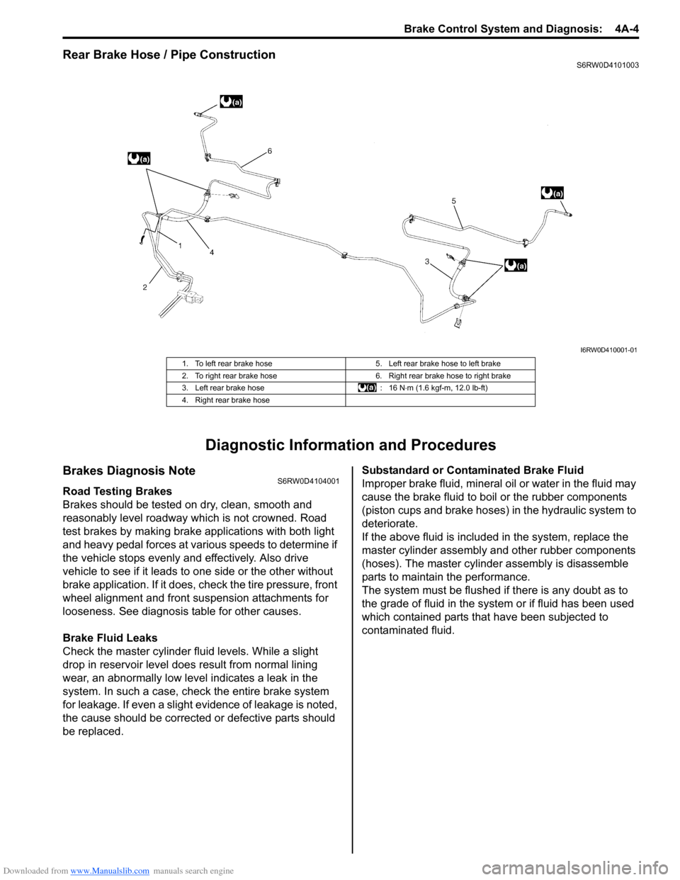
Rear Brake Hose / Pipe ConstructionS6RW0D4101003
Diagnostic Information and Procedures
Brakes Diagnosis NoteS6RW0D4104001
Road Testing Brakes
Brakes should be tested on dry, clean, smooth and
reasonably level roadway which is not crowned. Road
test brakes by making brake applications with both light
and heavy pedal forces at various speeds to determine if
the vehicle stops evenly and effectively. Also drive
vehicle to see if it leads to one side or the other without
brake application. If it does, check the tire pressure, front
wheel alignment and front suspension attachments for
looseness. See diagnosis table for other causes.
Brake Fluid Leaks
Check the master cylinder fluid levels. While a slight
drop in reservoir level does result from normal lining
wear, an abnormally low level indicates a leak in the
system. In such a case, check the entire brake system
for leakage. If even a slight evidence of leakage is noted,
the cause should be corrected or defective parts should
be replaced.Substandard or Contaminated Brake Fluid
Improper brake fluid, mineral oil or water in the fluid may
cause the brake fluid to boil or the rubber components
(piston cups and brake hoses) in the hydraulic system to
deteriorate.
If the above fluid is included in the system, replace the
master cylinder assembly and other rubber components
(hoses). The master cylinder assembly is disassemble
parts to maintain the performance.
The system must be flushed if there is any doubt as to
the grade of fluid in the system or if fluid has been used
which contained parts that have been subjected to
contaminated fluid.
I6RW0D410001-01
1. To left rear brake hose 5. Left rear brake hose to left brake
2. To right rear brake hose 6. Right rear brake hose to right brake
3. Left rear brake hose : 16 N⋅m (1.6 kgf-m, 12.0 lb-ft)
4. Right rear brake hose
Page 576 of 1556
Downloaded from www.Manualslib.com manuals search engine 4A-5 Brake Control System and Diagnosis:
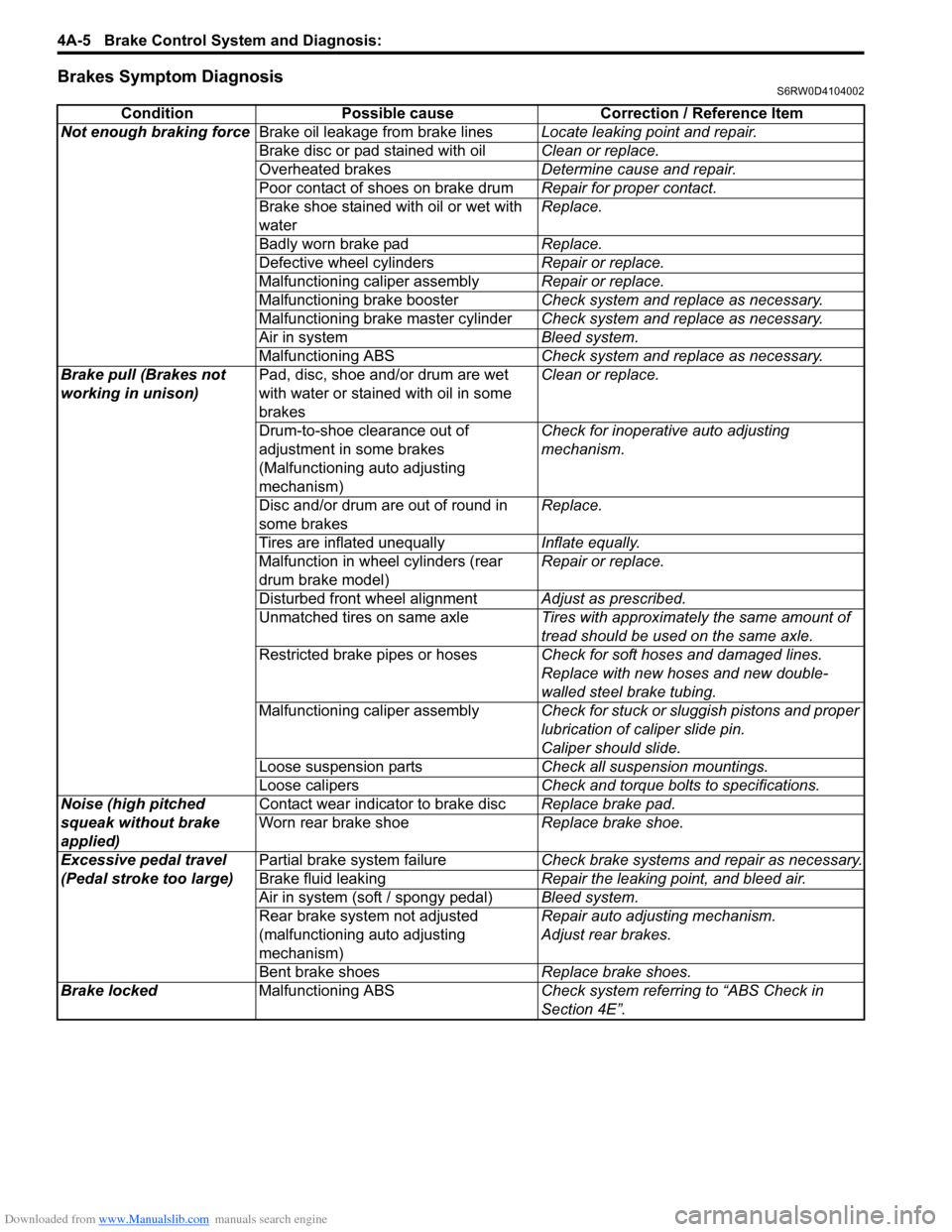
Brakes Symptom DiagnosisS6RW0D4104002
Condition Possible cause Correction / Reference Item
Not enough braking forceBrake oil leakage from brake linesLocate leaking point and repair.
Brake disc or pad stained with oilClean or replace.
Overheated brakesDetermine cause and repair.
Poor contact of shoes on brake drumRepair for proper contact.
Brake shoe stained with oil or wet with
waterReplace.
Badly worn brake padReplace.
Defective wheel cylindersRepair or replace.
Malfunctioning caliper assemblyRepair or replace.
Malfunctioning brake boosterCheck system and replace as necessary.
Malfunctioning brake master cylinderCheck system and replace as necessary.
Air in systemBleed system.
Malfunctioning ABSCheck system and replace as necessary.
Brake pull (Brakes not
working in unison)Pad, disc, shoe and/or drum are wet
with water or stained with oil in some
brakesClean or replace.
Drum-to-shoe clearance out of
adjustment in some brakes
(Malfunctioning auto adjusting
mechanism) Check for inoperative auto adjusting
mechanism.
Disc and/or drum are out of round in
some brakesReplace.
Tires are inflated unequallyInflate equally.
Malfunction in wheel cylinders (rear
drum brake model)Repair or replace.
Disturbed front wheel alignmentAdjust as prescribed.
Unmatched tires on same axleTires with approximately the same amount of
tread should be used on the same axle.
Restricted brake pipes or hosesCheck for soft hoses and damaged lines.
Replace with new hoses and new double-
walled steel brake tubing.
Malfunctioning caliper assemblyCheck for stuck or sluggish pistons and proper
lubrication of caliper slide pin.
Caliper should slide.
Loose suspension partsCheck all suspension mountings.
Loose calipersCheck and torque bolts to specifications.
Noise (high pitched
squeak without brake
applied)Contact wear indicator to brake discReplace brake pad.
Worn rear brake shoeReplace brake shoe.
Excessive pedal travel
(Pedal stroke too large)Partial brake system failureCheck brake systems and repair as necessary.
Brake fluid leakingRepair the leaking point, and bleed air.
Air in system (soft / spongy pedal)Bleed system.
Rear brake system not adjusted
(malfunctioning auto adjusting
mechanism)Repair auto adjusting mechanism.
Adjust rear brakes.
Bent brake shoesReplace brake shoes.
Brake locked Malfunctioning ABSCheck system referring to “ABS Check in
Section 4E”.
Page 581 of 1556
Downloaded from www.Manualslib.com manuals search engine Brake Control System and Diagnosis: 4A-10
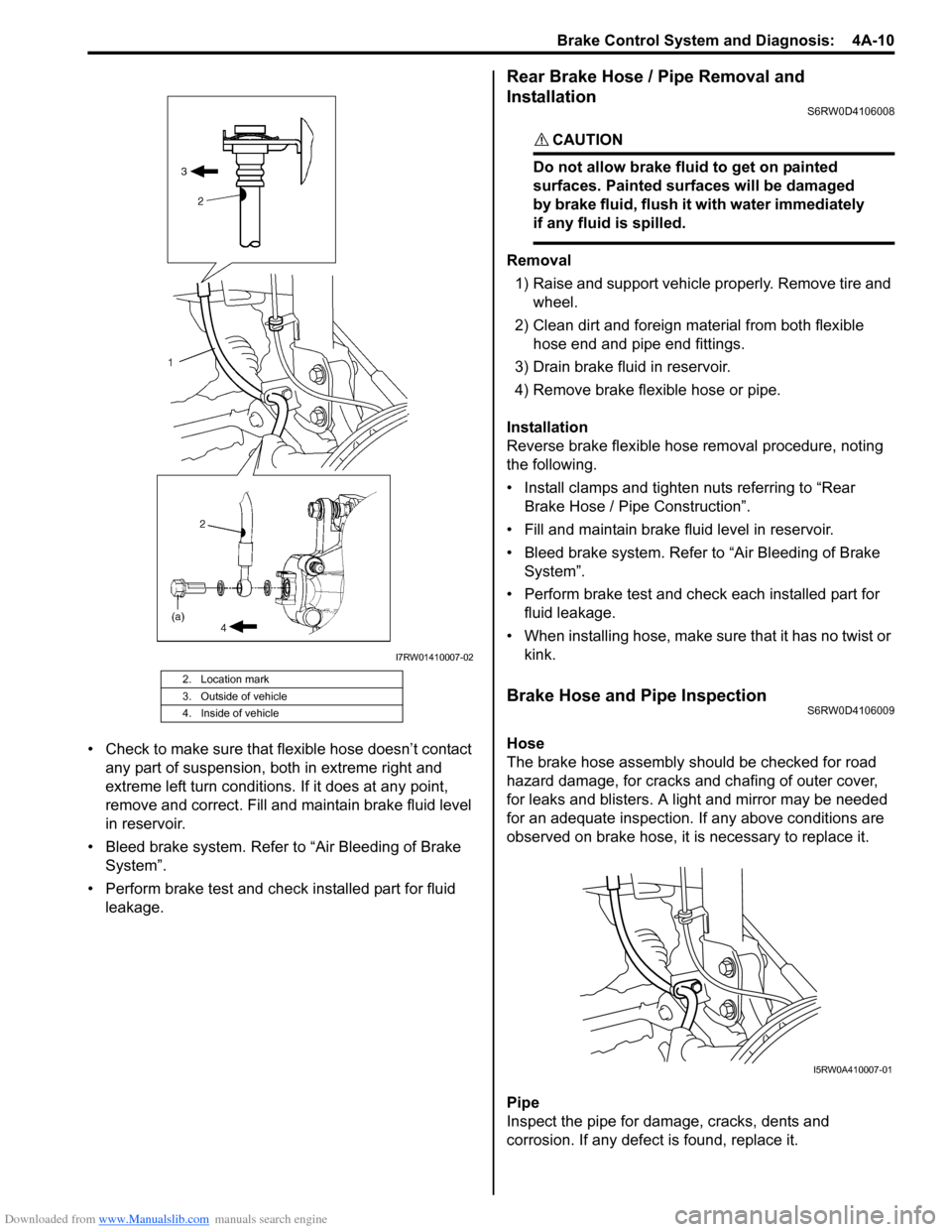
• Check to make sure that flexible hose doesn’t contact
any part of suspension, both in extreme right and
extreme left turn conditions. If it does at any point,
remove and correct. Fill and maintain brake fluid level
in reservoir.
• Bleed brake system. Refer to “Air Bleeding of Brake
System”.
• Perform brake test and check installed part for fluid
leakage.
Rear Brake Hose / Pipe Removal and
Installation
S6RW0D4106008
CAUTION!
Do not allow brake fluid to get on painted
surfaces. Painted surfaces will be damaged
by brake fluid, flush it with water immediately
if any fluid is spilled.
Removal
1) Raise and support vehicle properly. Remove tire and
wheel.
2) Clean dirt and foreign material from both flexible
hose end and pipe end fittings.
3) Drain brake fluid in reservoir.
4) Remove brake flexible hose or pipe.
Installation
Reverse brake flexible hose removal procedure, noting
the following.
• Install clamps and tighten nuts referring to “Rear
Brake Hose / Pipe Construction”.
• Fill and maintain brake fluid level in reservoir.
• Bleed brake system. Refer to “Air Bleeding of Brake
System”.
• Perform brake test and check each installed part for
fluid leakage.
• When installing hose, make sure that it has no twist or
kink.
Brake Hose and Pipe InspectionS6RW0D4106009
Hose
The brake hose assembly should be checked for road
hazard damage, for cracks and chafing of outer cover,
for leaks and blisters. A light and mirror may be needed
for an adequate inspection. If any above conditions are
observed on brake hose, it is necessary to replace it.
Pipe
Inspect the pipe for damage, cracks, dents and
corrosion. If any defect is found, replace it.
2. Location mark
3. Outside of vehicle
4. Inside of vehicle
I7RW01410007-02
I5RW0A410007-01
Page 666 of 1556
Downloaded from www.Manualslib.com manuals search engine 5A-18 Automatic Transmission/Transaxle:
Step 2. DTC / Freeze Frame Data Check, Record and
Clearance
First, referring to “DTC Check”, check DTC and pending
DTC. If DTC exists, print or write down DTC and freeze
frame data and then clear malfunction DTC(s) by
referring to “DTC Clearance”. Malfunction DTC indicates
malfunction in the system but it is not possible to know
from it whether the malfunction is occurring now or it
occurred in the past and normal condition has been
restored. In order to know that, check symptom in
question according to Step 5 and then recheck DTC
according to Step 6.
Diagnosing a trouble based on the DTC in this step only
or failure to clear the DTC in this step may result in an
faulty diagnosis, trouble diagnosis of a normal circuit or
difficulty in troubleshooting which is otherwise
unnecessary.
Step 3 and 4. Visual Inspection
As a preliminary step, be sure to perform visual check of
the items that support proper function of the engine and
automatic transaxle referring to “Visual Inspection”.
Step 5. Trouble Symptom Confirmation
Check trouble symptoms based on information obtained
in “Step 1. Customer Complaint Analysis: ” and “Step 2.
DTC / Freeze Frame Data Check, Record and
Clearance: ”.
Also, reconfirm DTC according to “DTC Confirmation
Procedure” described in each DTC flow.
Step 6 and 7. Rechecking and Record of DTC and
Freeze Frame Data
Refer to “DTC Check” for checking procedure.Step 8. A/T Basic Check and A/T Symptom
Diagnosis
Perform basic check of A/T according to “A/T Basic
Check” first. When the end of the flow has been reached,
check the parts of the system suspected as a possible
cause referring to “A/T Symptom Diagnosis” and based
on symptoms appearing on the vehicle (symptoms
obtained through steps of customer complaint analysis,
trouble symptom confirmation and/or A/T basic check)
and repair or replace faulty parts, if any.
Step 9. Troubleshooting for DTC
Based on the DTC indicated in Step 6 / 7 and referring to
“applicable DTC flow”, locate the cause of the trouble,
namely in a sensor, switch, wire harness, connector,
actuator, TCM or other part and repair or replace faulty
parts.
Step 10. Check for Intermittent Problem
Check parts where an intermittent trouble is easy to
occur (e.g. wire harness, connector, etc.), referring to
“Intermittent and Poor Connection Inspection in Section
00” and related circuit of DTC recorded in Step 2.
Step 11. Final Confirmation Test
Confirm that the problem symptom has gone and the
vehicle is free from any abnormal conditions. If what has
been repaired is related to the malfunction DTC, clear
the DTC once and check to ensure that no malfunction
DTC is indicated.
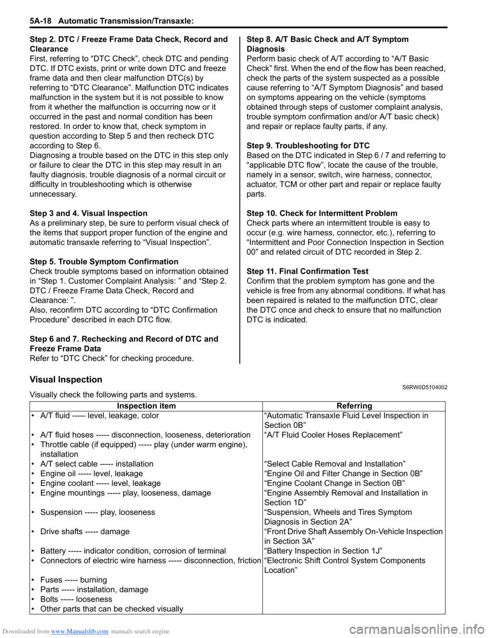
Visual InspectionS6RW0D5104002
Visually check the following parts and systems.
Inspection item Referring
• A/T fluid ----- level, leakage, color “Automatic Transaxle Fluid Level Inspection in
Section 0B”
• A/T fluid hoses ----- disconnection, looseness, deterioration “A/T Fluid Cooler Hoses Replacement”
• Throttle cable (if equipped) ----- play (under warm engine),
installation
• A/T select cable ----- installation “Select Cable Removal and Installation”
• Engine oil ----- level, leakage “Engine Oil and Filter Change in Section 0B”
• Engine coolant ----- level, leakage “Engine Coolant Change in Section 0B”
• Engine mountings ----- play, looseness, damage “Engine Assembly Removal and Installation in
Section 1D”
• Suspension ----- play, looseness “Suspension, Wheels and Tires Symptom
Diagnosis in Section 2A”
• Drive shafts ----- damage “Front Drive Shaft Assembly On-Vehicle Inspection
in Section 3A”
• Battery ----- indicator condition, corrosion of terminal “Battery Inspection in Section 1J”
• Connectors of electric wire harness ----- disconnection, friction “Electronic Shift Control System Components
Location”
• Fuses ----- burning
• Parts ----- installation, damage
• Bolts ----- looseness
• Other parts that can be checked visually
Page 824 of 1556
Downloaded from www.Manualslib.com manuals search engine 5B-12 Manual Transmission/Transaxle:
Manual Transaxle Unit Dismounting and
Remounting
S6RW0D5206010
Dismounting
1) Drain coolant.
2) Remove battery and tray with ECM.
3) Remove air cleaner case and resonator.
4) Remove clutch fluid pipe referring to “Clutch Fluid
Pipe Removal and Installation in Section 5C”.
5) Disconnect back up light switch coupler and undo
wiring harness clamps.
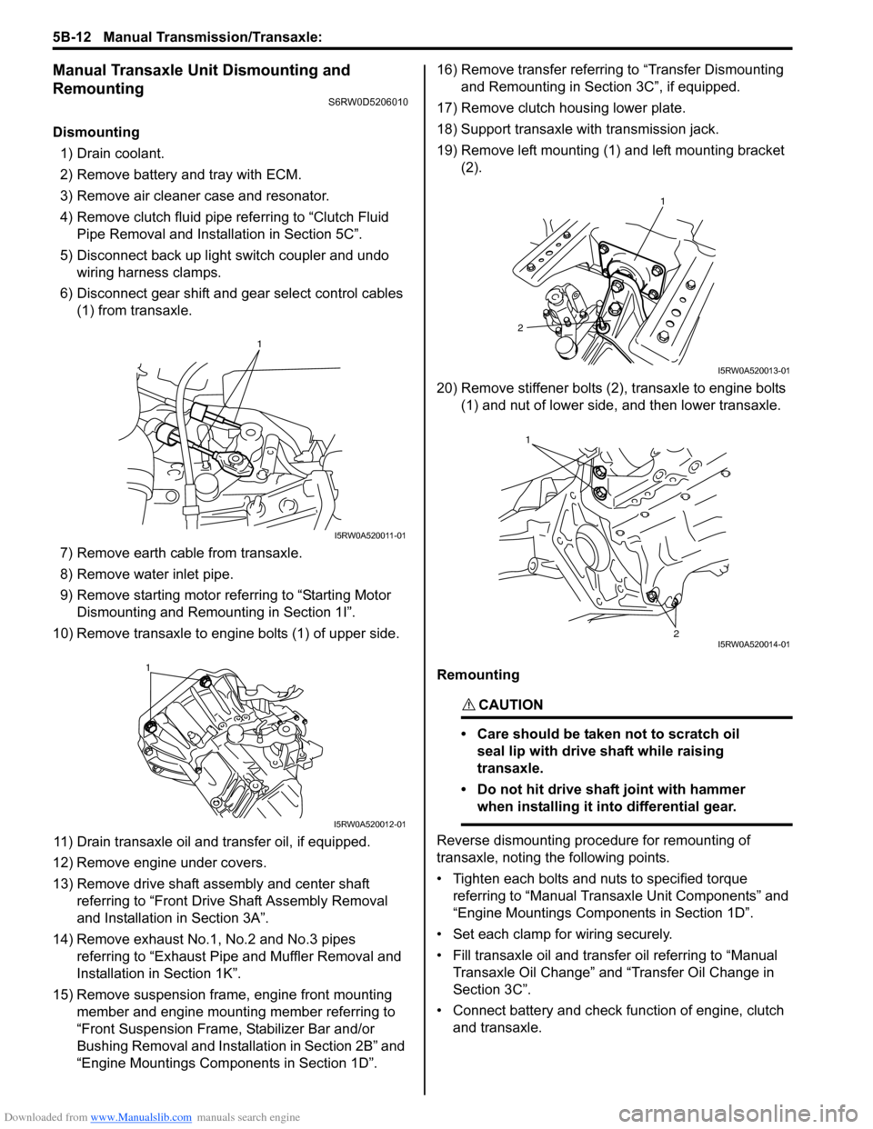
6) Disconnect gear shift and gear select control cables
(1) from transaxle.
7) Remove earth cable from transaxle.
8) Remove water inlet pipe.
9) Remove starting motor referring to “Starting Motor
Dismounting and Remounting in Section 1I”.
10) Remove transaxle to engine bolts (1) of upper side.
11) Drain transaxle oil and transfer oil, if equipped.
12) Remove engine under covers.
13) Remove drive shaft assembly and center shaft
referring to “Front Drive Shaft Assembly Removal
and Installation in Section 3A”.
14) Remove exhaust No.1, No.2 and No.3 pipes
referring to “Exhaust Pipe and Muffler Removal and
Installation in Section 1K”.
15) Remove suspension frame, engine front mounting
member and engine mounting member referring to
“Front Suspension Frame, Stabilizer Bar and/or
Bushing Removal and Installation in Section 2B” and
“Engine Mountings Components in Section 1D”.16) Remove transfer referring to “Transfer Dismounting
and Remounting in Section 3C”, if equipped.
17) Remove clutch housing lower plate.
18) Support transaxle with transmission jack.
19) Remove left mounting (1) and left mounting bracket
(2).
20) Remove stiffener bolts (2), transaxle to engine bolts
(1) and nut of lower side, and then lower transaxle.
Remounting
CAUTION!
• Care should be taken not to scratch oil
seal lip with drive shaft while raising
transaxle.
• Do not hit drive shaft joint with hammer
when installing it into differential gear.
Reverse dismounting procedure for remounting of
transaxle, noting the following points.
• Tighten each bolts and nuts to specified torque
referring to “Manual Transaxle Unit Components” and
“Engine Mountings Components in Section 1D”.
• Set each clamp for wiring securely.
• Fill transaxle oil and transfer oil referring to “Manual
Transaxle Oil Change” and “Transfer Oil Change in
Section 3C”.
• Connect battery and check function of engine, clutch
and transaxle.
1
I5RW0A520011-01
1
I5RW0A520012-01
1
2
I5RW0A520013-01
1
2I5RW0A520014-01