generator SUZUKI SX4 2006 1.G Service Repair Manual
[x] Cancel search | Manufacturer: SUZUKI, Model Year: 2006, Model line: SX4, Model: SUZUKI SX4 2006 1.GPages: 1556, PDF Size: 37.31 MB
Page 1232 of 1556

Downloaded from www.Manualslib.com manuals search engine 9A-65 Wiring Systems:
2C39
LT GRN
1
C47C01
C01
GRN/ORNGRN/REDBRN/YEL
WHT/RED
C122
3
BLK/REDBLK/REDBLK/REDBLK/RED
55
RED/BLKGRY/RED
GRY/BLU
Weld spliceC311
EGR
valve
4
6312
5
3
4 5 6
MAP
sensor
C363
1
2
C124
ECM
C912
1C922
1C932
1C942
1
#2 #1#3
#4
BLU/REDBLU/WHTBLU/YELBLU/ORN
BLK/RED
BLK/RED
BLU/BLK
EVAP
canister
purge
valve
C123
ECT
sensor
GRY/BLU
GRY/BLUBLK/REDGRYBLU/YELBRN/WHT
"A-4"
Lg
30ARDTR
10
Relay
motor
"A-1"
Generator
BLU/REDLT GRNBRNGRN
BR
BY
46E015017
1
1
2
13 17
16 2
1
242528
26
27
21 4
3
5
LT GRN/BLK
2
57
E371 C343
18
19
OCV
1
2
6059
BLK/REDBLK/REDGRYGRY
BLK/RED
BLK/RED
BLK/RED
4
32
1E226
PNK/BLK
BW
8
GRY/BLU
YEL
Individual circuit
fuse box (No.1)
15ATHR
MOR
3
YEL/BLK
MAF sensor
4
53
1E222
Throttle
motor
relay
M
I6RW0C910936-04
Page 1236 of 1556

Downloaded from www.Manualslib.com manuals search engine 9A-69 Wiring Systems:
2C39
LT GRN
1
C47 C01
C01
C124
ECM
C912
1C922
1C932
1C942
1
#2 #1#3
#4
BLU/REDBLU/WHTBLU/YELBLU/ORN
BLK/RED
BLU/BLKGRN/ORNGRN/REDBRN/YEL
WHT/RED
EVAP
canister
purge
valve
C123 C122
ECT
sensor
GRY/BLU
GRY/BLU
"A-4"
Lg
30ARDTR
10
Relay
motor
"A-1"
Generator
BLU/REDLT GRNBRNGRN
BR
BY
46E014532
1
1
2
29 17
16 2
1
242528
26
27
21 4
3
5
BLK/YEL
2
3
55
E371 C343
18
19
OCV
1
2
6059
BLK/REDBLK/REDGRYGRYBLK/REDBLK/REDBLK/REDBLK/RED
BLK/RED
BLK/RED
BLK/RED
4
32
1E226
GRN/BLK
GRYBLK/REDBLU/YEL
53
RED/BLKGRY/RED
GRY/BLUGRY/BLU
GRN/RED
Individual circuit
fuse box (No.1)
15ATHR
MOR
3
GRN/WHT
MAF sensor
IF EQPD
4
53
1E222
Throttle
motor
relay
M
Weld spliceC311
EGR
valve IF EQPD
IF EQPD
4
6312
5
19
18 4 3
MAP
sensor
C363
1
2
I6RW0D910928-01
Page 1240 of 1556

Downloaded from www.Manualslib.com manuals search engine 9A-73 Wiring Systems:
2C39
LT GRN
1
C47C01
C01
Pressure
switch
C64
ECM
C912
1C922
1C932
1C942
1
#2 #1#3
#4
BLU/REDBLU/WHTBLU/YELBLU/ORN
BLK/RED
GRN/BLK
BLU/WHT
BLU/BLK
EVAP
canister
purge
valve
C123
ECT
sensor
GRY/BLU
GRY/BLU
GRY
"A-4"
Lg
G
30ARDTR
10
Relay
#1
motor
"A-1"
Generator
BLU/REDBLU/BLKBLKLT GRNBRNGRN
BR
"A-4"motor
BB
"A-4"motor
BW
BY
4647E015017
1
1
2
13 17
16 2
1
242528
26
27
43 1
5
2
LT GRN/BLK
2
57
E371 C343
18
19
C163
GRN
1
7
VIM
motor
1
2
4243
BLK/REDBLK/REDGRYGRYGRYGRNGRN
BLU/REDBLU/RED
BLK/RED
BLK/RED
BLK/RED
BLK/RED
4
32
1E226
PNK/BLK
GRYBLK/REDBLU/YEL
BW
8
BRN/WHT
GRY/BLU
YEL
Individual circuit
fuse box (No.1)
15ATHR
MOR
3
YEL/BLK
MAF sensor IF EQPD
4
53
1E222
Relay
#2
4
51
3E223
Relay
#3
5
41
3E224
Throttle
motor
relay
9
M
I6RW0C910945-03
Page 1249 of 1556
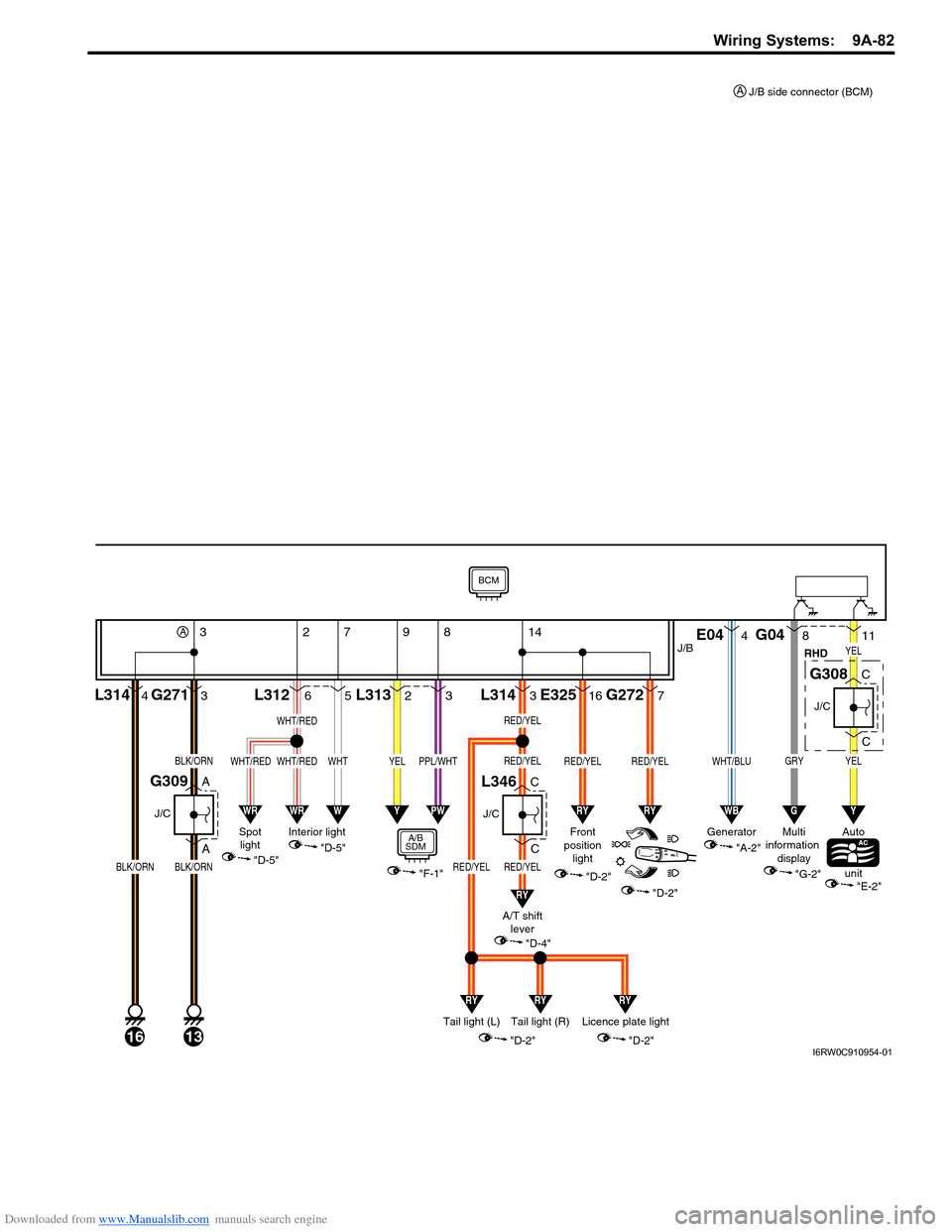
Downloaded from www.Manualslib.com manuals search engine Wiring Systems: 9A-82
3
A
AG2716L312
13
J/C
G309
BLK/ORNBLK/ORN
4L314
16
BLK/ORN
C
C
J/C
G308
C
C
J/C
L346
YEL
"A-2" GeneratorRHD"D-5" Spot
light"D-5" Interior light
E044
WHT/BLU
WB
WHT/REDWHT/RED
WHT/RED
WRWR
11YEL
Y
GRY
8G04
G
"G-2" Multi
information
display
BCM
Auto
unit
"E-2"
J/B
A3142
5
WHT
W
7
2L313
YEL
Y
9
7G272
RED/YEL
RY
16E325
RED/YEL
RY
3L314
RED/YELRED/YEL
RED/YEL
RED/YEL
RY
RYRYRY
3
PPL/WHT
PW
8
J/B side connector (BCM) A
"F-1"
A/B
SDMFront
position
light
"D-2"
A/T shift
lever
"D-4"
"D-2"
Tail light (L) Tail light (R)Licence plate light
"D-2"
"D-2"I6RW0C910954-01
Page 1253 of 1556
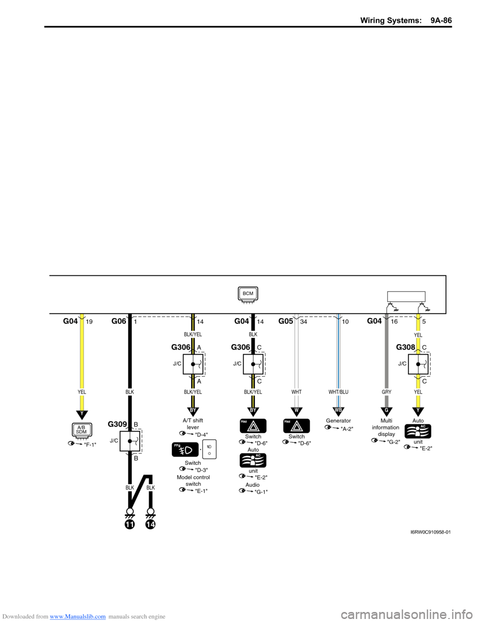
Downloaded from www.Manualslib.com manuals search engine Wiring Systems: 9A-86
19G041
B
BG06
11
J/C
G309
A
A
J/C
G306
BLK
14
BLK
"F-1"
YELBLK
A/B
SDM
Switch
Auto
unit"D-6"
Model control
switch
"E-1""E-2"
A/T shift
lever
"D-4"
Switch
"D-3"
Audio
"G-1"
Y
G0434G05
WHT
W
14
BLK/YEL
BLK/YEL
BY
C
C
J/C
G306
14
BLK/YEL
C
C
J/C
G308
YEL
BLK
BY
"A-2" Generator
10
WHT/BLU
WB
5
YEL
Y
GRY
16G04
G
"G-2" Multi
information
display
BCM
Auto
unit
"E-2"
Switch
"D-6"
I6RW0C910958-01
Page 1329 of 1556
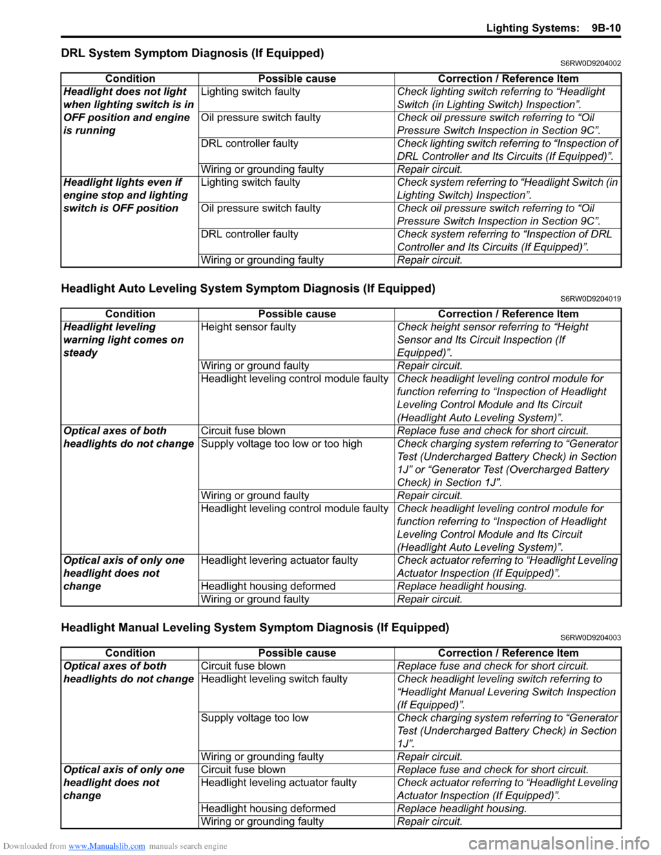
Downloaded from www.Manualslib.com manuals search engine Lighting Systems: 9B-10
DRL System Symptom Diagnosis (If Equipped)S6RW0D9204002
Headlight Auto Leveling System Symptom Diagnosis (If Equipped)S6RW0D9204019
Headlight Manual Leveling System Symptom Diagnosis (If Equipped)S6RW0D9204003
Condition Possible cause Correction / Reference Item
Headlight does not light
when lighting switch is in
OFF position and engine
is runningLighting switch faultyCheck lighting switch referring to “Headlight
Switch (in Lighting Switch) Inspection”.
Oil pressure switch faultyCheck oil pressure switch referring to “Oil
Pressure Switch Inspection in Section 9C”.
DRL controller faultyCheck lighting switch referring to “Inspection of
DRL Controller and Its Circuits (If Equipped)”.
Wiring or grounding faultyRepair circuit.
Headlight lights even if
engine stop and lighting
switch is OFF positionLighting switch faultyCheck system referring to “Headlight Switch (in
Lighting Switch) Inspection”.
Oil pressure switch faultyCheck oil pressure switch referring to “Oil
Pressure Switch Inspection in Section 9C”.
DRL controller faultyCheck system referring to “Inspection of DRL
Controller and Its Circuits (If Equipped)”.
Wiring or grounding faultyRepair circuit.
Condition Possible cause Correction / Reference Item
Headlight leveling
warning light comes on
steadyHeight sensor faultyCheck height sensor referring to “Height
Sensor and Its Circuit Inspection (If
Equipped)”.
Wiring or ground faultyRepair circuit.
Headlight leveling control module faultyCheck headlight leveling control module for
function referring to “Inspection of Headlight
Leveling Control Module and Its Circuit
(Headlight Auto Leveling System)”.
Optical axes of both
headlights do not changeCircuit fuse blownReplace fuse and check for short circuit.
Supply voltage too low or too highCheck charging system referring to “Generator
Test (Undercharged Battery Check) in Section
1J” or “Generator Test (Overcharged Battery
Check) in Section 1J”.
Wiring or ground faultyRepair circuit.
Headlight leveling control module faultyCheck headlight leveling control module for
function referring to “Inspection of Headlight
Leveling Control Module and Its Circuit
(Headlight Auto Leveling System)”.
Optical axis of only one
headlight does not
changeHeadlight levering actuator faultyCheck actuator referring to “Headlight Leveling
Actuator Inspection (If Equipped)”.
Headlight housing deformedReplace headlight housing.
Wiring or ground faultyRepair circuit.
Condition Possible cause Correction / Reference Item
Optical axes of both
headlights do not changeCircuit fuse blownReplace fuse and check for short circuit.
Headlight leveling switch faultyCheck headlight leveling switch referring to
“Headlight Manual Levering Switch Inspection
(If Equipped)”.
Supply voltage too lowCheck charging system referring to “Generator
Test (Undercharged Battery Check) in Section
1J”.
Wiring or grounding faultyRepair circuit.
Optical axis of only one
headlight does not
changeCircuit fuse blownReplace fuse and check for short circuit.
Headlight leveling actuator faultyCheck actuator referring to “Headlight Leveling
Actuator Inspection (If Equipped)”.
Headlight housing deformedReplace headlight housing.
Wiring or grounding faultyRepair circuit.
Page 1330 of 1556
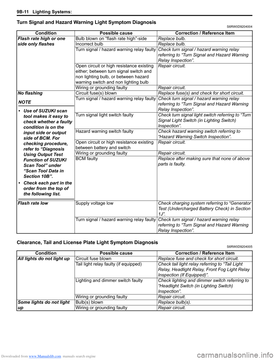
Downloaded from www.Manualslib.com manuals search engine 9B-11 Lighting Systems:
Turn Signal and Hazard Warning Light Symptom DiagnosisS6RW0D9204004
Clearance, Tail and License Plate Light Symptom DiagnosisS6RW0D9204005
Condition Possible cause Correction / Reference Item
Flash rate high or one
side only flashesBulb blown on “flash rate high”-sideReplace bulb.
Incorrect bulbReplace bulb.
Turn signal / hazard warning relay faultyCheck turn signal / hazard warning relay
referring to “Turn Signal and Hazard Warning
Relay Inspection”.
Open circuit or high resistance existing
either; between turn signal switch and
non lighting bulb, or between hazard
warning switch and non lighting bulbRepair circuit.
Wiring or grounding faultyRepair circuit.
No flashing
NOTE
• Use of SUZUKI scan
tool makes it easy to
check whether a faulty
condition is on the
input side or output
side of BCM. For
checking procedure,
refer to “Diagnosis
Using Output Test
Function of SUZUKI
Scan Tool” under
“Scan Tool Data in
Section 10B”.
• Check each part in the
order from the top of
the following list.
Circuit fuse(s) blownReplace fuse(s) and check for short circuit.
Turn signal / hazard warning relay faultyCheck turn signal / hazard warning relay
referring to “Turn Signal and Hazard Warning
Relay Inspection”.
Turn signal light switch faultyCheck turn signal light switch referring to “Turn
Signal Light Switch (in Lighting Switch)
Inspection”.
Hazard warning switch faultyCheck hazard warning switch referring to
“Hazard Warning Switch Inspection”.
Open circuit or high resistance existing
between battery and switchRepair circuit.
Wiring or grounding faultyRepair circuit.
BCM faultyReplace after making sure that none of above
parts is faulty.
Flash rate lowSupply voltage lowCheck charging system referring to “Generator
Test (Undercharged Battery Check) in Section
1J”.
Turn signal / hazard warning relay faultyCheck turn signal / hazard warning relay
referring to “Turn Signal and Hazard Warning
Relay Inspection”.
Condition Possible cause Correction / Reference Item
All lights do not light upCircuit fuse blownReplace fuse and check for short circuit.
Tail light relay faulty (if equipped)Check tail light relay referring to “Tail Light
Relay, Headlight Relay, Front Fog Light Relay
Inspection (If Equipped)”.
Lighting and dimmer switch faultyCheck lighting and dimmer switch referring to
“Headlight Switch (in Lighting Switch)
Inspection”.
Wiring or grounding faultyRepair circuit.
Some lights do not light
upBulb(s) blownReplace bulb(s).
Wiring or grounding faultyRepair circuit.
Page 1478 of 1556
Downloaded from www.Manualslib.com manuals search engine 10B-5 Body Electrical Control System:
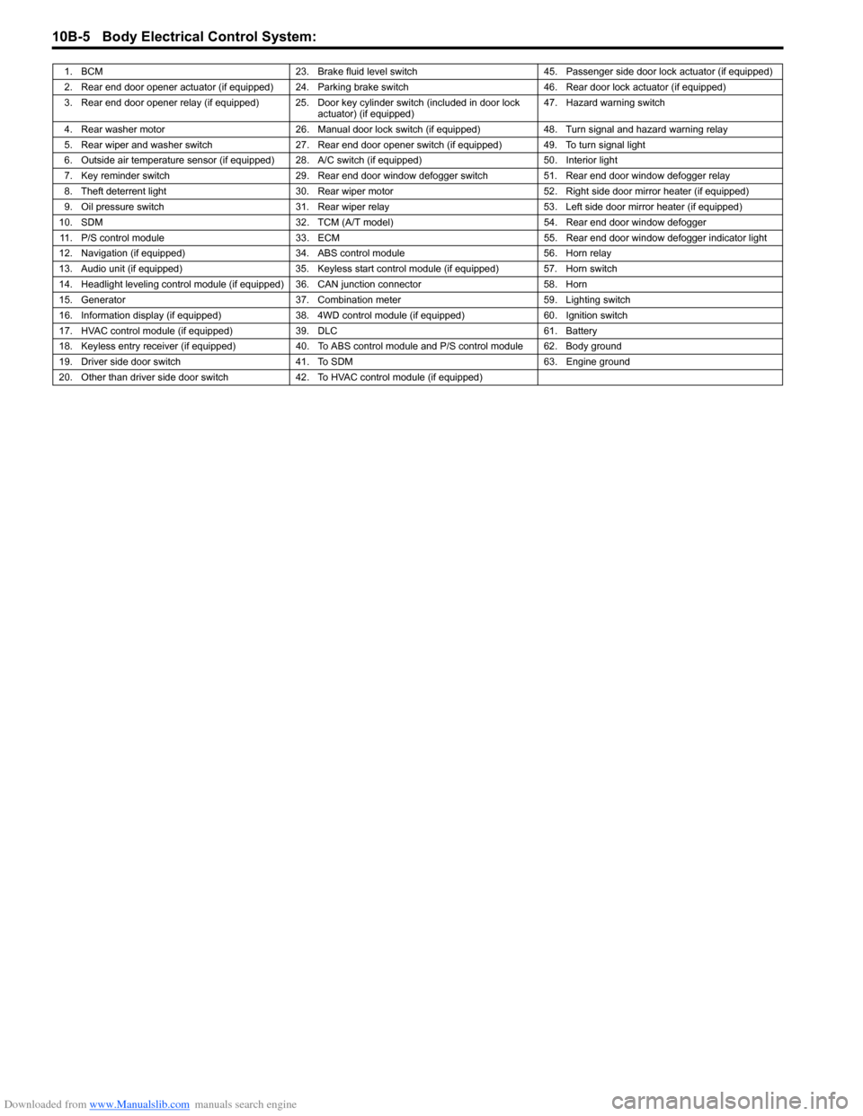
1. BCM 23. Brake fluid level switch 45. Passenger side door lock actuator (if equipped)
2. Rear end door opener actuator (if equipped) 24. Parking brake switch 46. Rear door lock actuator (if equipped)
3. Rear end door opener relay (if equipped) 25. Door key cylinder switch (included in door lock
actuator) (if equipped)47. Hazard warning switch
4. Rear washer motor 26. Manual door lock switch (if equipped) 48. Turn signal and hazard warning relay
5. Rear wiper and washer switch 27. Rear end door opener switch (if equipped) 49. To turn signal light
6. Outside air temperature sensor (if equipped) 28. A/C switch (if equipped) 50. Interior light
7. Key reminder switch 29. Rear end door window defogger switch 51. Rear end door window defogger relay
8. Theft deterrent light 30. Rear wiper motor 52. Right side door mirror heater (if equipped)
9. Oil pressure switch 31. Rear wiper relay 53. Left side door mirror heater (if equipped)
10. SDM 32. TCM (A/T model) 54. Rear end door window defogger
11. P/S control module 33. ECM 55. Rear end door window defogger indicator light
12. Navigation (if equipped) 34. ABS control module 56. Horn relay
13. Audio unit (if equipped) 35. Keyless start control module (if equipped) 57. Horn switch
14. Headlight leveling control module (if equipped) 36. CAN junction connector 58. Horn
15. Generator 37. Combination meter 59. Lighting switch
16. Information display (if equipped) 38. 4WD control module (if equipped) 60. Ignition switch
17. HVAC control module (if equipped) 39. DLC 61. Battery
18. Keyless entry receiver (if equipped) 40. To ABS control module and P/S control module 62. Body ground
19. Driver side door switch 41. To SDM 63. Engine ground
20. Other than driver side door switch 42. To HVAC control module (if equipped)
Page 1480 of 1556
Downloaded from www.Manualslib.com manuals search engine 10B-7 Body Electrical Control System:
Component Location
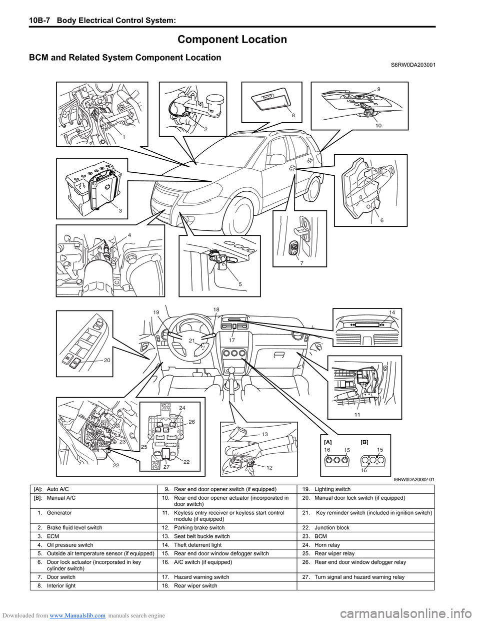
BCM and Related System Component LocationS6RW0DA203001
13
12 17 18
21 19
14
24 25
2526
2722 23
22
2476
20
11
5
151615
16 [A] [B]
2
9
10
3
8
4
1
I6RW0DA20002-01
[A]: Auto A/C 9. Rear end door opener switch (if equipped) 19. Lighting switch
[B]: Manual A/C 10. Rear end door opener actuator (incorporated in
door switch)20. Manual door lock switch (if equipped)
1. Generator 11. Keyless entry receiver or keyless start control
module (if equipped)21. Key reminder switch (included in ignition switch)
2. Brake fluid level switch 12. Parking brake switch 22. Junction block
3. ECM 13. Seat belt buckle switch 23. BCM
4. Oil pressure switch 14. Theft deterrent light 24. Horn relay
5. Outside air temperature sensor (if equipped) 15. Rear end door window defogger switch 25. Rear wiper relay
6. Door lock actuator (incorporated in key
cylinder switch)16. A/C switch (if equipped) 26. Rear end door window defogger relay
7. Door switch 17. Hazard warning switch 27. Turn signal and hazard warning relay
8. Interior light 18. Rear wiper switch
Page 1481 of 1556
Downloaded from www.Manualslib.com manuals search engine Body Electrical Control System: 10B-8
Diagnostic Information and Procedures
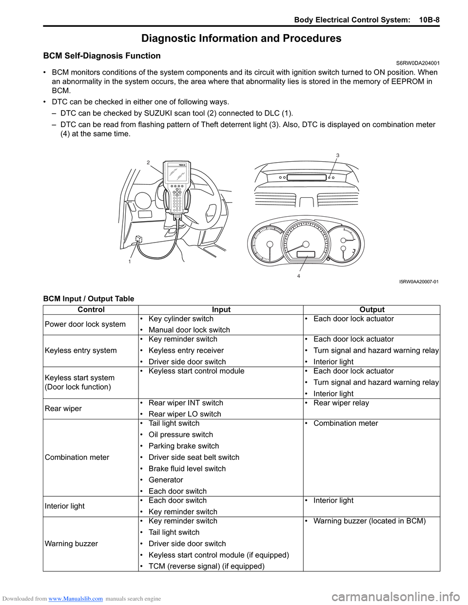
BCM Self-Diagnosis FunctionS6RW0DA204001
• BCM monitors conditions of the system components and its circuit with ignition switch turned to ON position. When
an abnormality in the system occurs, the area where that abnormality lies is stored in the memory of EEPROM in
BCM.
• DTC can be checked in either one of following ways.
– DTC can be checked by SUZUKI scan tool (2) connected to DLC (1).
– DTC can be read from flashing pattern of Theft deterrent light (3). Also, DTC is displayed on combination meter
(4) at the same time.
BCM Input / Output Table
3
4
2
1
I5RW0AA20007-01
Control Input Output
Power door lock system• Key cylinder switch
• Manual door lock switch• Each door lock actuator
Keyless entry system• Key reminder switch
• Keyless entry receiver
• Driver side door switch• Each door lock actuator
• Turn signal and hazard warning relay
• Interior light
Keyless start system
(Door lock function)• Keyless start control module • Each door lock actuator
• Turn signal and hazard warning relay
• Interior light
Rear wiper • Rear wiper INT switch
• Rear wiper LO switch• Rear wiper relay
Combination meter• Tail light switch
• Oil pressure switch
• Parking brake switch
• Driver side seat belt switch
• Brake fluid level switch
• Generator
• Each door switch• Combination meter
Interior light• Each door switch
• Key reminder switch• Interior light
Warning buzzer• Key reminder switch
• Tail light switch
• Driver side door switch
• Keyless start control module (if equipped)
• TCM (reverse signal) (if equipped)• Warning buzzer (located in BCM)