key SUZUKI SX4 2006 1.G Service Repair Manual
[x] Cancel search | Manufacturer: SUZUKI, Model Year: 2006, Model line: SX4, Model: SUZUKI SX4 2006 1.GPages: 1556, PDF Size: 37.31 MB
Page 1165 of 1556
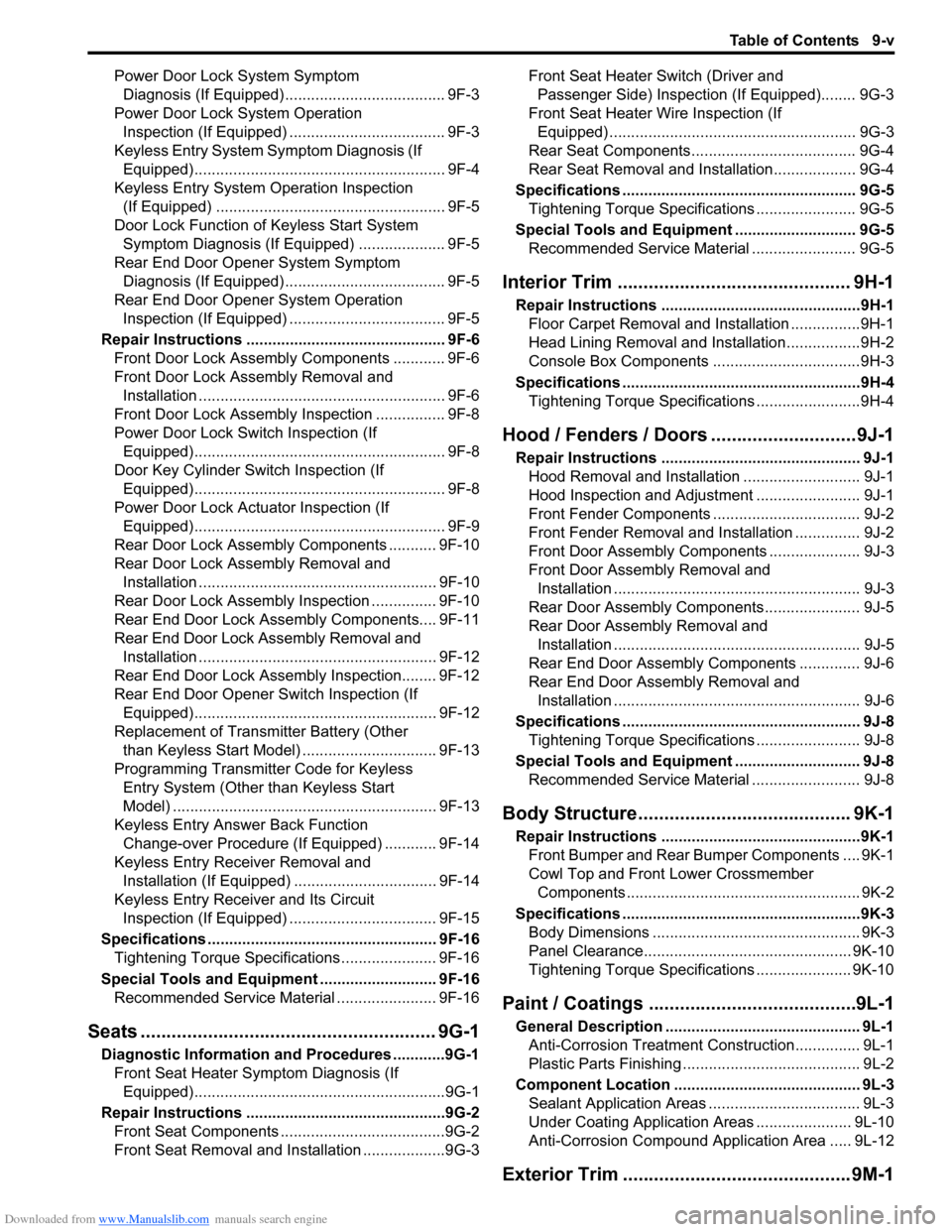
Downloaded from www.Manualslib.com manuals search engine Table of Contents 9-v
Power Door Lock System Symptom
Diagnosis (If Equipped)..................................... 9F-3
Power Door Lock System Operation
Inspection (If Equipped) .................................... 9F-3
Keyless Entry System Symptom Diagnosis (If
Equipped).......................................................... 9F-4
Keyless Entry System Operation Inspection
(If Equipped) ..................................................... 9F-5
Door Lock Function of Keyless Start System
Symptom Diagnosis (If Equipped) .................... 9F-5
Rear End Door Opener System Symptom
Diagnosis (If Equipped)..................................... 9F-5
Rear End Door Opener System Operation
Inspection (If Equipped) .................................... 9F-5
Repair Instructions .............................................. 9F-6
Front Door Lock Assembly Components ............ 9F-6
Front Door Lock Assembly Removal and
Installation ......................................................... 9F-6
Front Door Lock Assembly Inspection ................ 9F-8
Power Door Lock Switch Inspection (If
Equipped).......................................................... 9F-8
Door Key Cylinder Switch Inspection (If
Equipped).......................................................... 9F-8
Power Door Lock Actuator Inspection (If
Equipped).......................................................... 9F-9
Rear Door Lock Assembly Components ........... 9F-10
Rear Door Lock Assembly Removal and
Installation ....................................................... 9F-10
Rear Door Lock Assembly Inspection ............... 9F-10
Rear End Door Lock Assembly Components.... 9F-11
Rear End Door Lock Assembly Removal and
Installation ....................................................... 9F-12
Rear End Door Lock Assembly Inspection........ 9F-12
Rear End Door Opener Switch Inspection (If
Equipped)........................................................ 9F-12
Replacement of Transmitter Battery (Other
than Keyless Start Model) ............................... 9F-13
Programming Transmitter Code for Keyless
Entry System (Other than Keyless Start
Model) ............................................................. 9F-13
Keyless Entry Answer Back Function
Change-over Procedure (If Equipped) ............ 9F-14
Keyless Entry Receiver Removal and
Installation (If Equipped)................................. 9F-14
Keyless Entry Receiver and Its Circuit
Inspection (If Equipped) .................................. 9F-15
Specifications..................................................... 9F-16
Tightening Torque Specifications ...................... 9F-16
Special Tools and Equipment ........................... 9F-16
Recommended Service Material ....................... 9F-16
Seats ......................................................... 9G-1
Diagnostic Information and Procedures ............9G-1
Front Seat Heater Symptom Diagnosis (If
Equipped)..........................................................9G-1
Repair Instructions ..............................................9G-2
Front Seat Components ......................................9G-2
Front Seat Removal and Installation ...................9G-3Front Seat Heater Switch (Driver and
Passenger Side) Inspection (If Equipped)........ 9G-3
Front Seat Heater Wire Inspection (If
Equipped) ......................................................... 9G-3
Rear Seat Components...................................... 9G-4
Rear Seat Removal and Installation................... 9G-4
Specifications ...................................................... 9G-5
Tightening Torque Specifications ....................... 9G-5
Special Tools and Equipment ............................ 9G-5
Recommended Service Material ........................ 9G-5
Interior Trim ............................................. 9H-1
Repair Instructions ..............................................9H-1
Floor Carpet Removal and Installation ................9H-1
Head Lining Removal and Installation.................9H-2
Console Box Components ..................................9H-3
Specifications .......................................................9H-4
Tightening Torque Specifications ........................9H-4
Hood / Fenders / Doors ............................ 9J-1
Repair Instructions .............................................. 9J-1
Hood Removal and Installation ........................... 9J-1
Hood Inspection and Adjustment ........................ 9J-1
Front Fender Components .................................. 9J-2
Front Fender Removal and Installation ............... 9J-2
Front Door Assembly Components ..................... 9J-3
Front Door Assembly Removal and
Installation ......................................................... 9J-3
Rear Door Assembly Components...................... 9J-5
Rear Door Assembly Removal and
Installation ......................................................... 9J-5
Rear End Door Assembly Components .............. 9J-6
Rear End Door Assembly Removal and
Installation ......................................................... 9J-6
Specifications ....................................................... 9J-8
Tightening Torque Specifications ........................ 9J-8
Special Tools and Equipment ............................. 9J-8
Recommended Service Material ......................... 9J-8
Body Structure......................................... 9K-1
Repair Instructions ..............................................9K-1
Front Bumper and Rear Bumper Components .... 9K-1
Cowl Top and Front Lower Crossmember
Components ...................................................... 9K-2
Specifications .......................................................9K-3
Body Dimensions ................................................ 9K-3
Panel Clearance................................................ 9K-10
Tightening Torque Specifications ...................... 9K-10
Paint / Coatings ........................................9L-1
General Description ............................................. 9L-1
Anti-Corrosion Treatment Construction............... 9L-1
Plastic Parts Finishing ......................................... 9L-2
Component Location ........................................... 9L-3
Sealant Application Areas ................................... 9L-3
Under Coating Application Areas ...................... 9L-10
Anti-Corrosion Compound Application Area ..... 9L-12
Exterior Trim ............................................ 9M-1
Page 1168 of 1556
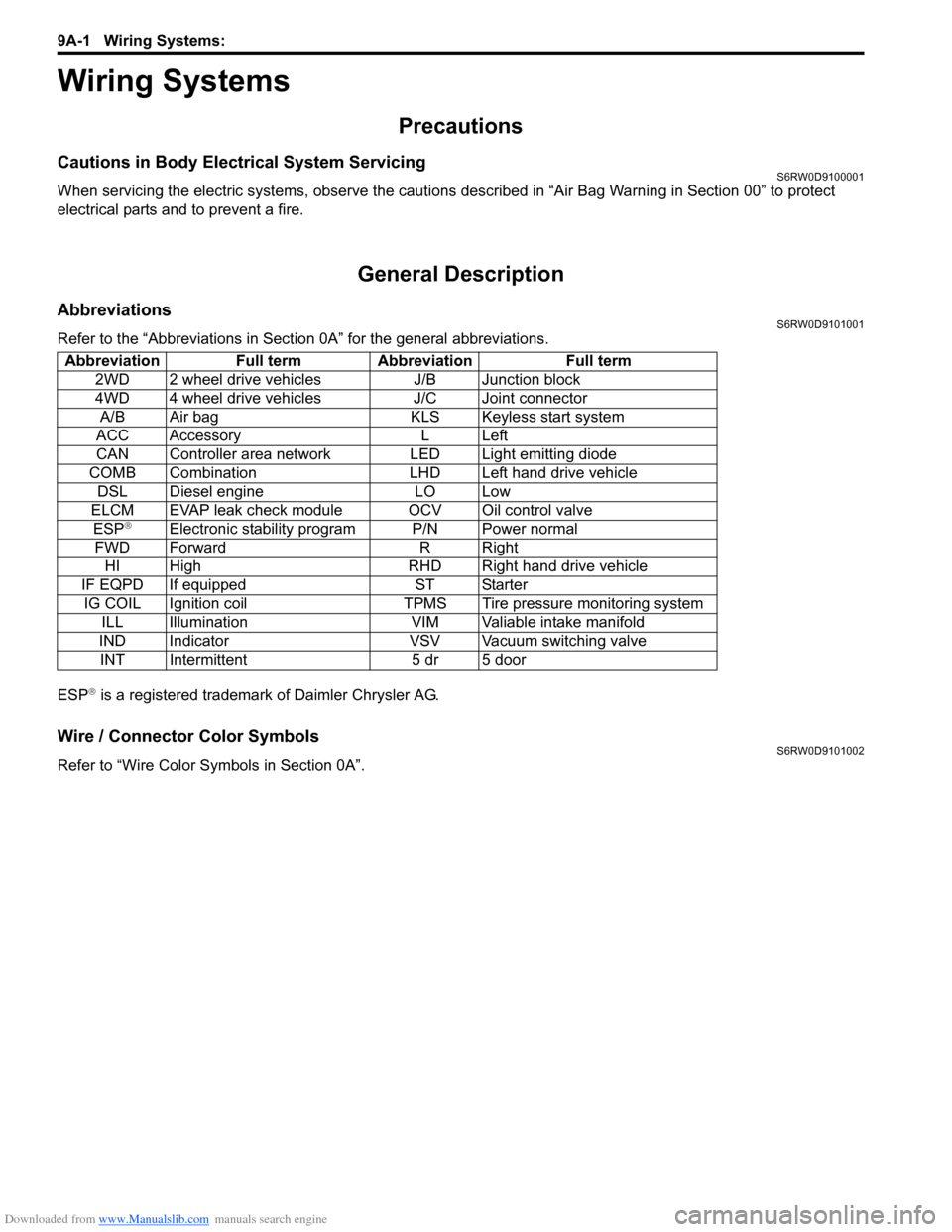
Downloaded from www.Manualslib.com manuals search engine 9A-1 Wiring Systems:
Body, Cab and Accessories
Wiring Systems
Precautions
Cautions in Body Electrical System ServicingS6RW0D9100001
When servicing the electric systems, observe the cautions described in “Air Bag Warning in Section 00” to protect
electrical parts and to prevent a fire.
General Description
AbbreviationsS6RW0D9101001
Refer to the “Abbreviations in Section 0A” for the general abbreviations.
ESP
® is a registered trademark of Daimler Chrysler AG.
Wire / Connector Color SymbolsS6RW0D9101002
Refer to “Wire Color Symbols in Section 0A”. Abbreviation Full term Abbreviation Full term
2WD 2 wheel drive vehicles J/B Junction block
4WD 4 wheel drive vehicles J/C Joint connector
A/B Air bag KLS Keyless start system
ACC Accessory L Left
CAN Controller area network LED Light emitting diode
COMB Combination LHD Left hand drive vehicle
DSL Diesel engine LO Low
ELCM EVAP leak check module OCV Oil control valve
ESP
®Electronic stability program P/N Power normal
FWD Forward R Right
HI High RHD Right hand drive vehicle
IF EQPD If equipped ST Starter
IG COIL Ignition coil TPMS Tire pressure monitoring system
ILL Illumination VIM Valiable intake manifold
IND Indicator VSV Vacuum switching valve
INT Intermittent 5 dr 5 door
Page 1170 of 1556
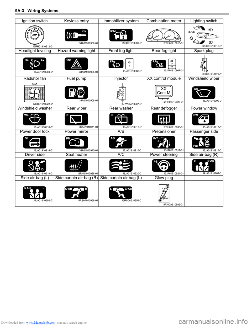
Downloaded from www.Manualslib.com manuals search engine 9A-3 Wiring Systems:
Ignition switch Keyless entry Immobilizer system Combination meter Lighting switch
Headlight leveling Hazard warning light Front fog light Rear fog light Spark plug
Radiator fan Fuel pump Injector XX control module Windshield wiper
Windshield washer Rear wiper Rear washer Rear defogger Power window
Power door lock Power mirror A/B Pretensioner Passenger side
Driver side Seat heater A/C Power steering Side air-bag (R)
Side air-bag (L) Side curtain air-bag (R) Side curtain air bag (L) Glow plug
I2RH01910912-01I3JA01910902-01I5RH01910901-01I2RH01910915-01I2RH01910916-01
I3JA01910904-01I3JA01910905-01I3JA01910906-01I3JA01910907-01I2RH01910921-01
I2RH01910922-01I3JA01910908-01I5RW0A910987-01
XX
Cont M
I2RH01910925-01I3JA01910909-01
I3JA01910910-01I3JA01910911-01I3JA01910912-01I2RH01910930-01I3JA01910913-01
I3JA01910914-01I3JA01910915-01I3JA01910916-01I3JA01910917-01I3JA01910918-01
I3JA01910919-01I2RH01910938-01I3JA01910920-01I3JA01910921-01I4JA01910901-01
I4JA01910902-01I5RS0A910958-01I5RS0A910959-01
I5RW0A910986-01
Page 1188 of 1556

Downloaded from www.Manualslib.com manuals search engine 9A-21 Wiring Systems:
G: Instrument panel harness, Instrument panel antenna wire / S: Contact coil (RHD)
G: Instrument panel harness
G146G141G309
G34G26G253
G266G255
G144
G241
G17
G310G153
G248
G311
G61
G259
1311
14
G16
G341
(TO L374)
G354
(TO K154)
G342
(TO L375)
G348
(TO K153)
G254
G152
G04
G271
G272
G307
G211
G343
(TO L376)
G344
(TO L377) G147G345
(TO L378)
G334
(TO E382)
G333
(TO E381)
G20
S121S61
G32 G155 G154
G63
G62G65G64G273
G151
G150
G308
G306
G35
G251
G347
S172
G346
S171
GSS
Instrument panel
antenna wire
G243
G267
G14
G355
(TO L409)G335
(TO E383)
I6RW0D910901-01
No./Color Connective position No./Color Connective position
G04/BLU BCM G248/BLU Audio (Navigation)
G14/N (IF
EQPD)Auto leveling control module G251/N ACC socket
G16/N (IF
EQPD)KLS ECM G253/GRN Multi information display
G17/BLK ICMG254/N (IF
EQPD)Keyless receiver
G20/GRN
(Auto A/C)Auto A/C unitG255/BLK
(Auto A/C)Diode #1
G26/N (IF
EQPD)4WD control module G259/ORN Passenger inflator
G32/N EVAP thermistor G271/N J/B
G34/N (Auto A/
C)Room temperature sensor G272/N J/B
G35/N (Auto A/
C)Sunlight sensor G273/N J/B
G61/N Heater fan motor G306/N J/C
G62/BLK Fresh/Recircle actuatorG307/N (IF
EQPD)J/C
G63/BLK (Auto
A/C)Mode selecting actuator G308/N J/C
G64/BLK (Auto
A/C)Temperature control actuator G309/GRY J/C
G65/N Fan driverG310/N (Auto
A/C)J/C
G141/BLK COMB switch G311/GRY J/C
G144/N COMB switch G333/GRY Main harness (To E381)
G146/N Main switch (key) G334/BRN Main harness (To E382)
Page 1190 of 1556
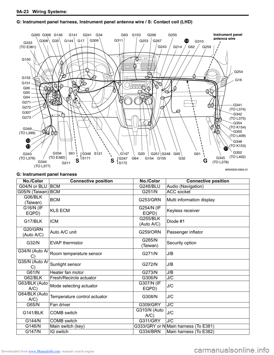
Downloaded from www.Manualslib.com manuals search engine 9A-23 Wiring Systems:
G: Instrument panel harness, Instrument panel antenna wire / S: Contact coil (LHD)
G: Instrument panel harness
G146G141
G309
G34
G253
G266G255
G144
G241
G17G311
G153 G63
G248
G310
G61
G259G243
G267
G355
(TO L409)
1311
14
G16
G341
(TO L374)
G354
(TO K154)
G342
(TO L375)
G348
(TO K153)
G352
(TO L402)
G254
G04
G271
G272
G307
12
G211
G343
(TO L376)G349
(TO L399)
G344
(TO L377)G147G345
(TO L378)
G334
(TO E382)
G333
(TO E381)
G20
S121S61
G32 G155 G154 G64
G62G214
G65 G273
G151
G152 G150
G05 G06
G308
G306 G265
G35
G251
G347
S172
G346
S171
G S S
Instrument panel
antenna wire
I6RW0D910902-01
No./Color Connective position No./Color Connective position
G04/N or BLU BCM G248/BLU Audio (Navigation)
G05/N (Taiwan) BCM G251/N ACC socket
G06/BLK
(Taiwan)BCM G253/GRN Multi information display
G16/N (IF
EQPD)KLS ECMG254/N (IF
EQPD)Keyless receiver
G17/BLK ICMG255/BLK
(Auto A/C)Diode #1
G20/GRN
(Auto A/C)Auto A/C unit G259/ORN Passenger inflator
G32/N EVAP thermistorG265/N
(Taiwan)Security option
G34/N (Auto A/
C)Room temperature sensor G271/N J/B
G35/N (Auto A/
C)Sunlight sensor G272/N J/B
G61/N Heater fan motor G273/N J/B
G62/BLK Fresh/Recircle actuator G306/N J/C
G63/BLK (Auto
A/C)Mode selecting actuatorG307/N (IF
EQPD)J/C
G64/BLK (Auto
A/C)Temperature control actuator G308/N J/C
G65/N Fan driver G309/GRY J/C
G141/BLK COMB switchG310/N (Auto
A/C)J/C
G144/N COMB switch G311/GRY J/C
G146/N Main switch (key) G333/GRY or N Main harness (To E381)
G147/N IG switch G334/BRN Main harness (To E382)
Page 1206 of 1556
Downloaded from www.Manualslib.com manuals search engine 9A-39 Wiring Systems:
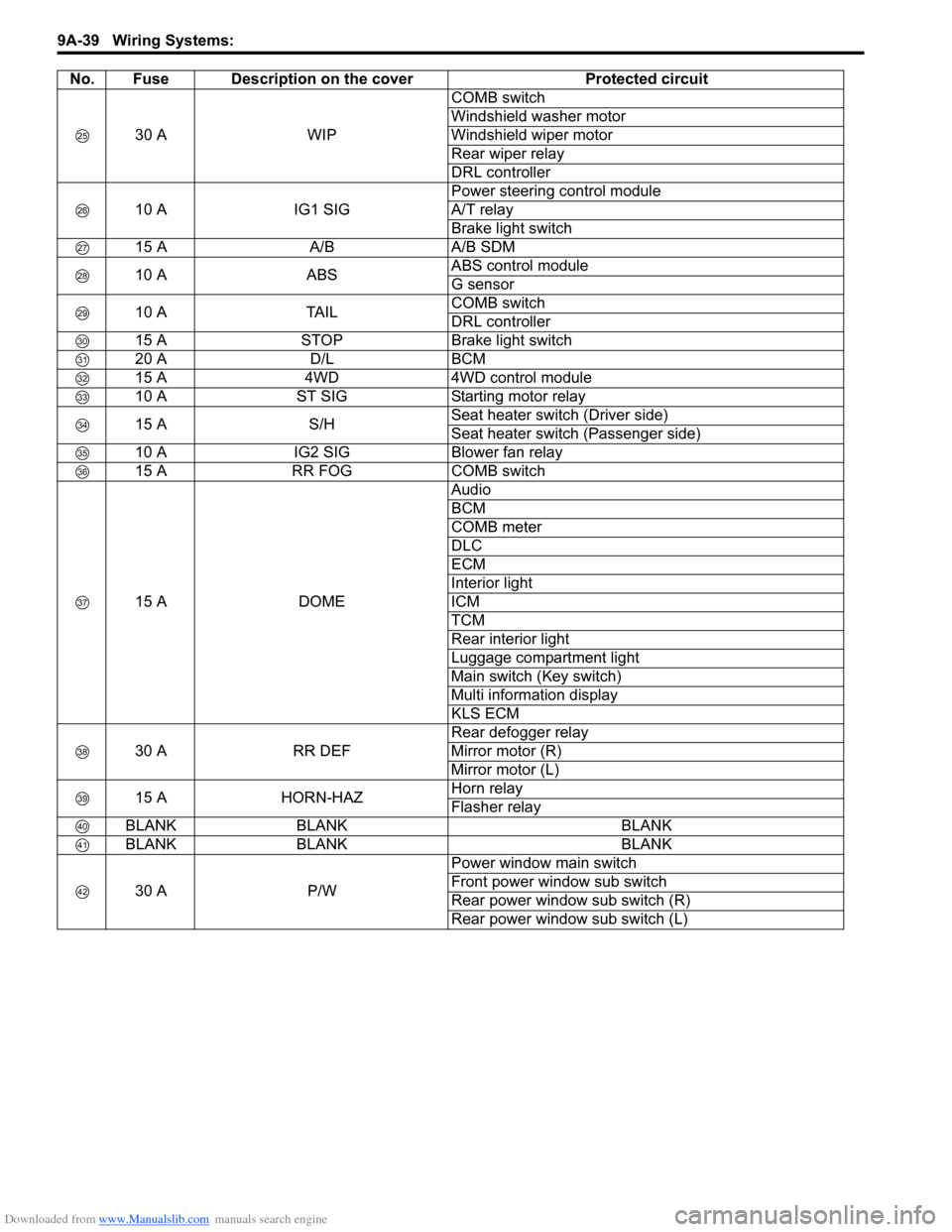
30 A WIPCOMB switch
Windshield washer motor
Windshield wiper motor
Rear wiper relay
DRL controller
10 A IG1 SIGPower steering control module
A/T relay
Brake light switch
15 A A/B A/B SDM
10 A ABSABS control module
G sensor
10 A TAILCOMB switch
DRL controller
15 A STOP Brake light switch
20 A D/L BCM
15 A 4WD 4WD control module
10 A ST SIG Starting motor relay
15 A S/HSeat heater switch (Driver side)
Seat heater switch (Passenger side)
10 A IG2 SIG Blower fan relay
15 A RR FOG COMB switch
15 A DOMEAudio
BCM
COMB meter
DLC
ECM
Interior light
ICM
TCM
Rear interior light
Luggage compartment light
Main switch (Key switch)
Multi information display
KLS ECM
30 A RR DEFRear defogger relay
Mirror motor (R)
Mirror motor (L)
15 A HORN-HAZHorn relay
Flasher relay
BLANK BLANK BLANK
BLANK BLANK BLANK
30 A P/WPower window main switch
Front power window sub switch
Rear power window sub switch (R)
Rear power window sub switch (L) No. Fuse Description on the cover Protected circuit
Page 1208 of 1556

Downloaded from www.Manualslib.com manuals search engine 9A-41 Wiring Systems:
10 A ABSABS control module
G sensor
BLANK BLANK BLANK
15 A STOP Brake light switch
20 A D/L BCM
BLANK BLANK BLANK
10 A ST SIG Starting motor relay
BLANK BLANK BLANK
10 A IG2 SIG Blower fan relay
10 A TAIL Tail light relay
15 A DOMEAudio
BCM
COMB meter
DLC
ECM
Interior light
ICM
TCM
Rear interior light
Luggage compartment light
Main switch (Key switch)
Multi information display
KLS ECM
30 A RR DEFRear defogger relay
Mirror motor (R)
Mirror motor (L)
15 A HORN-HAZHorn relay
Flasher relay
BLANK BLANK BLANK
BLANK BLANK BLANK
30 A P/WPower window main switch
Front power window sub switch
Rear power window sub switch (R)
Rear power window sub switch (L) No. Fuse Description on the cover Protected circuit
Page 1224 of 1556
Downloaded from www.Manualslib.com manuals search engine 9A-57 Wiring Systems:
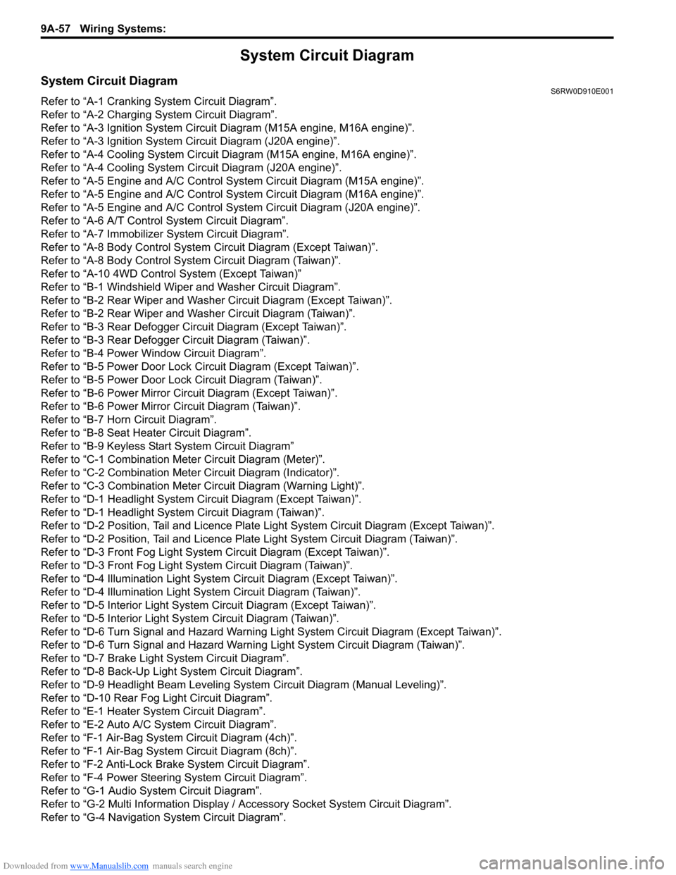
System Circuit Diagram
System Circuit DiagramS6RW0D910E001
Refer to “A-1 Cranking System Circuit Diagram”.
Refer to “A-2 Charging System Circuit Diagram”.
Refer to “A-3 Ignition System Circuit Diagram (M15A engine, M16A engine)”.
Refer to “A-3 Ignition System Circuit Diagram (J20A engine)”.
Refer to “A-4 Cooling System Circuit Diagram (M15A engine, M16A engine)”.
Refer to “A-4 Cooling System Circuit Diagram (J20A engine)”.
Refer to “A-5 Engine and A/C Control System Circuit Diagram (M15A engine)”.
Refer to “A-5 Engine and A/C Control System Circuit Diagram (M16A engine)”.
Refer to “A-5 Engine and A/C Control System Circuit Diagram (J20A engine)”.
Refer to “A-6 A/T Control System Circuit Diagram”.
Refer to “A-7 Immobilizer System Circuit Diagram”.
Refer to “A-8 Body Control System Circuit Diagram (Except Taiwan)”.
Refer to “A-8 Body Control System Circuit Diagram (Taiwan)”.
Refer to “A-10 4WD Control System (Except Taiwan)”
Refer to “B-1 Windshield Wiper and Washer Circuit Diagram”.
Refer to “B-2 Rear Wiper and Washer Circuit Diagram (Except Taiwan)”.
Refer to “B-2 Rear Wiper and Washer Circuit Diagram (Taiwan)”.
Refer to “B-3 Rear Defogger Circuit Diagram (Except Taiwan)”.
Refer to “B-3 Rear Defogger Circuit Diagram (Taiwan)”.
Refer to “B-4 Power Window Circuit Diagram”.
Refer to “B-5 Power Door Lock Circuit Diagram (Except Taiwan)”.
Refer to “B-5 Power Door Lock Circuit Diagram (Taiwan)”.
Refer to “B-6 Power Mirror Circuit Diagram (Except Taiwan)”.
Refer to “B-6 Power Mirror Circuit Diagram (Taiwan)”.
Refer to “B-7 Horn Circuit Diagram”.
Refer to “B-8 Seat Heater Circuit Diagram”.
Refer to “B-9 Keyless Start System Circuit Diagram”
Refer to “C-1 Combination Meter Circuit Diagram (Meter)”.
Refer to “C-2 Combination Meter Circuit Diagram (Indicator)”.
Refer to “C-3 Combination Meter Circuit Diagram (Warning Light)”.
Refer to “D-1 Headlight System Circuit Diagram (Except Taiwan)”.
Refer to “D-1 Headlight System Circuit Diagram (Taiwan)”.
Refer to “D-2 Position, Tail and Licence Plate Light System Circuit Diagram (Except Taiwan)”.
Refer to “D-2 Position, Tail and Licence Plate Light System Circuit Diagram (Taiwan)”.
Refer to “D-3 Front Fog Light System Circuit Diagram (Except Taiwan)”.
Refer to “D-3 Front Fog Light System Circuit Diagram (Taiwan)”.
Refer to “D-4 Illumination Light System Circuit Diagram (Except Taiwan)”.
Refer to “D-4 Illumination Light System Circuit Diagram (Taiwan)”.
Refer to “D-5 Interior Light System Circuit Diagram (Except Taiwan)”.
Refer to “D-5 Interior Light System Circuit Diagram (Taiwan)”.
Refer to “D-6 Turn Signal and Hazard Warning Light System Circuit Diagram (Except Taiwan)”.
Refer to “D-6 Turn Signal and Hazard Warning Light System Circuit Diagram (Taiwan)”.
Refer to “D-7 Brake Light System Circuit Diagram”.
Refer to “D-8 Back-Up Light System Circuit Diagram”.
Refer to “D-9 Headlight Beam Leveling System Circuit Diagram (Manual Leveling)”.
Refer to “D-10 Rear Fog Light Circuit Diagram”.
Refer to “E-1 Heater System Circuit Diagram”.
Refer to “E-2 Auto A/C System Circuit Diagram”.
Refer to “F-1 Air-Bag System Circuit Diagram (4ch)”.
Refer to “F-1 Air-Bag System Circuit Diagram (8ch)”.
Refer to “F-2 Anti-Lock Brake System Circuit Diagram”.
Refer to “F-4 Power Steering System Circuit Diagram”.
Refer to “G-1 Audio System Circuit Diagram”.
Refer to “G-2 Multi Information Display / Accessory Socket System Circuit Diagram”.
Refer to “G-4 Navigation System Circuit Diagram”.
Page 1247 of 1556

Downloaded from www.Manualslib.com manuals search engine Wiring Systems: 9A-80
15 7
"D-5"
16 BBG0410
BLU/YEL
BLU/YEL
J/C
G308
G146
1 47 4
Main switch
(Key switch)
RHD Flasher relay
DOME
G2715 15A
37ACC MTR
15A23
228
1
12
HORN
-HAZ
15A39
11
10A
22
WHT/RED
WHT/RED
YEL/REDYEL/BLK
1E37
2
Ambient
temperature
sensor
"B-5" Switch
614
1617125
RED/BLUBRN/YELLT GRN/BLKBRNGRY/WHTGRY/RED
Parking
brake
switchSeat
belt
switch
"C-3"
RBBY
115
RED/BLK
BB
Oil
pressure
switchBrake
fluid
level
switch
GRB
L01 L01E04
10E048
LgBBGWGR
Main switch
"B-5"
Sub switch
"B-5"
Front door
switch
Front door
switch
"D-5"
BRBR
BLK/BLUBLK/RED
BLK/REDBLK/REDBLK/RED
J/B
FF
Rear door
switch
"D-5"
BR
DD
J/CJ/C
L346
L347
AA
J/C
G307
BCM
GRY
J/B side connector (BCM) A
A
I6RW0C910952-02
Page 1251 of 1556

Downloaded from www.Manualslib.com manuals search engine Wiring Systems: 9A-84
38 39
"D-5""D-1"
BLK/BLU
3 AA BBG042
BLU/YEL
BLU/YEL
J/C
G307
1G265
J/C
G308
G146
1 4
Main switch
(Key switch)
DOME
G2715 15A
37ACC
G2725 15A
23
WHT/REDWHT/BLK
WHT/RED
YEL/RED
YEL/RED
YEL/BLK
YEL/BLK
1E37
2
Ambient
temperature
sensor
"B-5" Switch
840
37362726
RED/BLUBRN/YELLT GRN/BLKBRNGRY/WHTGRY/RED
Parking
brake
switchSeat
belt
switch
"C-3"
RBBY
97
RED/BLK
BB
GR
Oil
pressure
switchBrake
fluid
level
switch
Security
option
GRB
G05G0617
PNK
G04
24
GRY/RED
9G0521
LgBBGWGR
Main switch
"B-5"
Sub switch
"B-5"
Front door
switch
"D-3"Switch
Front door
switch
"D-5"
BRBR
BLK/RED
R
12
RED
BLK/BLUBLK/RED
BLK/REDBLK/REDBLK/RED
J/B
FF
Rear door
switch
"D-5"
BR
DD
J/CJ/C
L346
L347
BCM
GRY
E381
G33334
G343
L3761511
I6RW0C910956-01