meter SUZUKI SX4 2006 1.G Service Repair Manual
[x] Cancel search | Manufacturer: SUZUKI, Model Year: 2006, Model line: SX4, Model: SUZUKI SX4 2006 1.GPages: 1556, PDF Size: 37.31 MB
Page 327 of 1556
Downloaded from www.Manualslib.com manuals search engine Engine Mechanical: 1D-45
Valves and Valve Guides InspectionS6RW0D1406028
Valve Guide
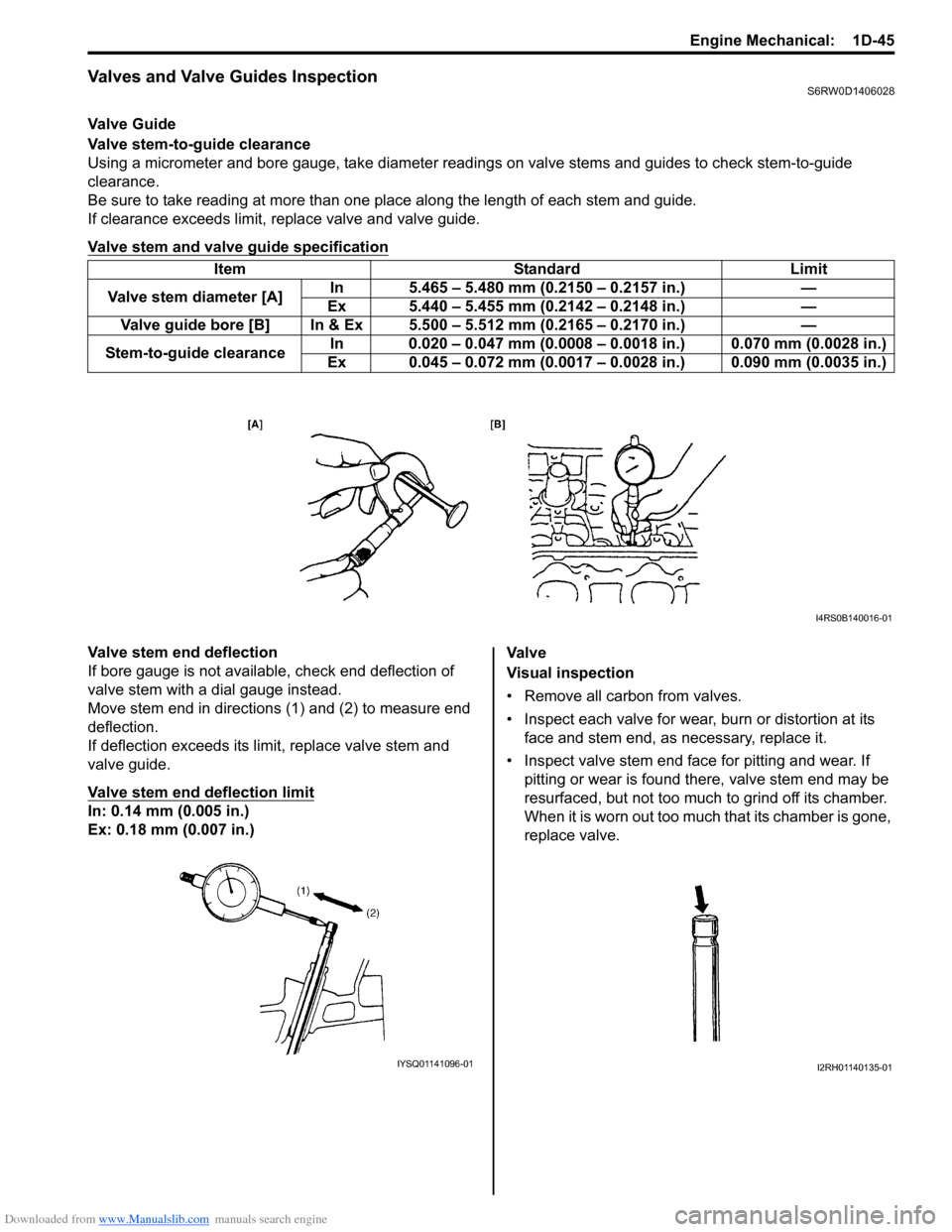
Valve stem-to-guide clearance
Using a micrometer and bore gauge, take diameter readings on valve stems and guides to check stem-to-guide
clearance.
Be sure to take reading at more than one place along the length of each stem and guide.
If clearance exceeds limit, replace valve and valve guide.
Valve stem and valve guide specification
Valve stem end deflection
If bore gauge is not available, check end deflection of
valve stem with a dial gauge instead.
Move stem end in directions (1) and (2) to measure end
deflection.
If deflection exceeds its limit, replace valve stem and
valve guide.
Valve stem end deflection limit
In: 0.14 mm (0.005 in.)
Ex: 0.18 mm (0.007 in.)Va l v e
Visual inspection
• Remove all carbon from valves.
• Inspect each valve for wear, burn or distortion at its
face and stem end, as necessary, replace it.
• Inspect valve stem end face for pitting and wear. If
pitting or wear is found there, valve stem end may be
resurfaced, but not too much to grind off its chamber.
When it is worn out too much that its chamber is gone,
replace valve. Item Standard Limit
Valve stem diameter [A]In 5.465 – 5.480 mm (0.2150 – 0.2157 in.) —
Ex 5.440 – 5.455 mm (0.2142 – 0.2148 in.) —
Valve guide bore [B] In & Ex 5.500 – 5.512 mm (0.2165 – 0.2170 in.) —
Stem-to-guide clearanceIn 0.020 – 0.047 mm (0.0008 – 0.0018 in.) 0.070 mm (0.0028 in.)
Ex 0.045 – 0.072 mm (0.0017 – 0.0028 in.) 0.090 mm (0.0035 in.)
I4RS0B140016-01
IYSQ01141096-01I2RH01140135-01
Page 331 of 1556
Downloaded from www.Manualslib.com manuals search engine Engine Mechanical: 1D-49
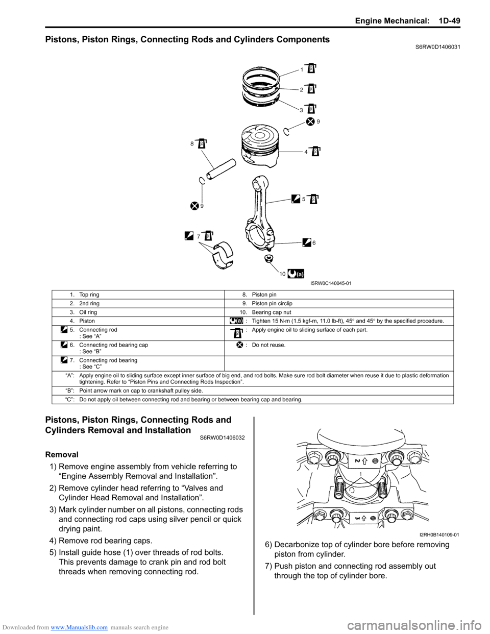
Pistons, Piston Rings, Connecting Rods and Cylinders ComponentsS6RW0D1406031
Pistons, Piston Rings, Connecting Rods and
Cylinders Removal and Installation
S6RW0D1406032
Removal
1) Remove engine assembly from vehicle referring to
“Engine Assembly Removal and Installation”.
2) Remove cylinder head referring to “Valves and
Cylinder Head Removal and Installation”.
3) Mark cylinder number on all pistons, connecting rods
and connecting rod caps using silver pencil or quick
drying paint.
4) Remove rod bearing caps.
5) Install guide hose (1) over threads of rod bolts.
This prevents damage to crank pin and rod bolt
threads when removing connecting rod.6) Decarbonize top of cylinder bore before removing
piston from cylinder.
7) Push piston and connecting rod assembly out
through the top of cylinder bore.
1. Top ring 8. Piston pin
2. 2nd ring 9. Piston pin circlip
3. Oil ring 10. Bearing cap nut
4. Piston : Tighten 15 N⋅m (1.5 kgf-m, 11.0 lb-ft), 45° and 45° by the specified procedure.
5. Connecting rod
: See “A”: Apply engine oil to sliding surface of each part.
6. Connecting rod bearing cap
: See “B”: Do not reuse.
7. Connecting rod bearing
: See “C”
“A”: Apply engine oil to sliding surface except inner surface of big end, and rod bolts. Make sure rod bolt diameter when reuse it due to plastic deformation
tightening. Refer to “Piston Pins and Connecting Rods Inspection”.
“B”: Point arrow mark on cap to crankshaft pulley side.
“C”: Do not apply oil between connecting rod and bearing or between bearing cap and bearing.
I5RW0C140045-01
I2RH0B140109-01
Page 334 of 1556
Downloaded from www.Manualslib.com manuals search engine 1D-52 Engine Mechanical:
Cylinders, Pistons and Piston Rings InspectionS6RW0D1406034
Cylinder
Visual inspection
Inspect cylinder walls for scratches, roughness or ridges
which indicate excessive wear. If cylinder bore is very
rough or deeply scratched, or ridged, rebore cylinder and
use over size piston.
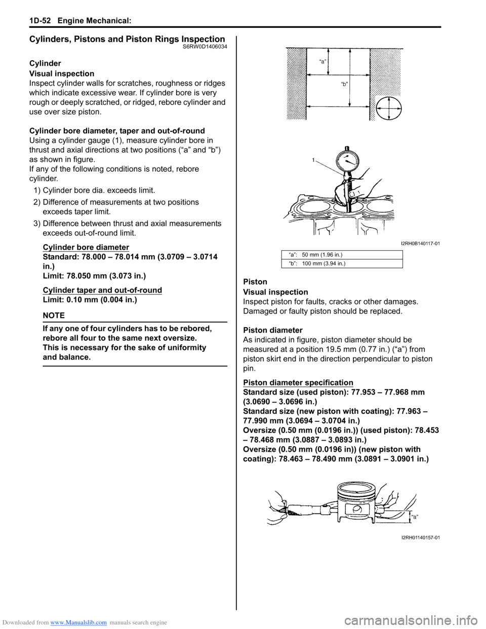
Cylinder bore diameter, taper and out-of-round
Using a cylinder gauge (1), measure cylinder bore in
thrust and axial directions at two positions (“a” and “b”)
as shown in figure.
If any of the following conditions is noted, rebore
cylinder.
1) Cylinder bore dia. exceeds limit.
2) Difference of measurements at two positions
exceeds taper limit.
3) Difference between thrust and axial measurements
exceeds out-of-round limit.
Cylinder bore diameter
Standard: 78.000 – 78.014 mm (3.0709 – 3.0714
in.)
Limit: 78.050 mm (3.073 in.)
Cylinder taper and out-of-round
Limit: 0.10 mm (0.004 in.)
NOTE
If any one of four cylinders has to be rebored,
rebore all four to the same next oversize.
This is necessary for the sake of uniformity
and balance.
Piston
Visual inspection
Inspect piston for faults, cracks or other damages.
Damaged or faulty piston should be replaced.
Piston diameter
As indicated in figure, piston diameter should be
measured at a position 19.5 mm (0.77 in.) (“a”) from
piston skirt end in the direction perpendicular to piston
pin.
Piston diameter specification
Standard size (used piston): 77.953 – 77.968 mm
(3.0690 – 3.0696 in.)
Standard size (new piston with coating): 77.963 –
77.990 mm (3.0694 – 3.0704 in.)
Oversize (0.50 mm (0.0196 in.)) (used piston): 78.453
– 78.468 mm (3.0887 – 3.0893 in.)
Oversize (0.50 mm (0.0196 in)) (new piston with
coating): 78.463 – 78.490 mm (3.0891 – 3.0901 in.)
“a”: 50 mm (1.96 in.)
“b”: 100 mm (3.94 in.)
I2RH0B140117-01
I2RH01140157-01
Page 335 of 1556
Downloaded from www.Manualslib.com manuals search engine Engine Mechanical: 1D-53
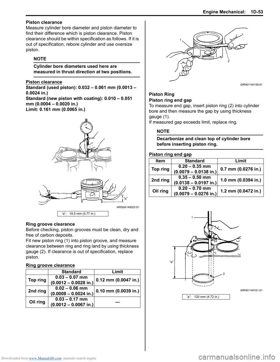
Piston clearance
Measure cylinder bore diameter and piston diameter to
find their difference which is piston clearance. Piston
clearance should be within specification as follows. If it is
out of specification, rebore cylinder and use oversize
piston.
NOTE
Cylinder bore diameters used here are
measured in thrust direction at two positions.
Piston clearance
Standard (used piston): 0.032 – 0.061 mm (0.0013 –
0.0024 in.)
Standard (new piston with coating): 0.010 – 0.051
mm (0.0004 – 0.0020 in.)
Limit: 0.161 mm (0.0065 in.)
Ring groove clearance
Before checking, piston grooves must be clean, dry and
free of carbon deposits.
Fit new piston ring (1) into piston groove, and measure
clearance between ring and ring land by using thickness
gauge (2). If clearance is out of specification, replace
piston.
Ring groove clearance
Piston Ring
Piston ring end gap
To measure end gap, insert piston ring (2) into cylinder
bore and then measure the gap by using thickness
gauge (1).
If measured gap exceeds limit, replace ring.
NOTE
Decarbonize and clean top of cylinder bore
before inserting piston ring.
Piston ring end gap
“a”: 19.5 mm (0.77 in.)
Standard Limit
To p r i n g0.03 – 0.07 mm
(0.0012 – 0.0028 in.)0.12 mm (0.0047 in.)
2nd ring0.02 – 0.06 mm
(0.0008 – 0.0024 in.)0.10 mm (0.0039 in.)
Oil ring0.03 – 0.17 mm
(0.0012 – 0.0067 in.)—
I4RS0A140022-01
Item Standard Limit
To p r i n g0.20 – 0.35 mm
(0.0079 – 0.0138 in.)0.7 mm (0.0276 in.)
2nd ring0.35 – 0.50 mm
(0.0138 – 0.0197 in.)1.0 mm (0.0394 in.)
Oil ring0.20 – 0.70 mm
(0.0079 – 0.0276 in.)1.2 mm (0.0472 in.)
“a”: 120 mm (4.72 in.)
I2RH01140159-01
I2RH01140161-01
Page 337 of 1556
Downloaded from www.Manualslib.com manuals search engine Engine Mechanical: 1D-55
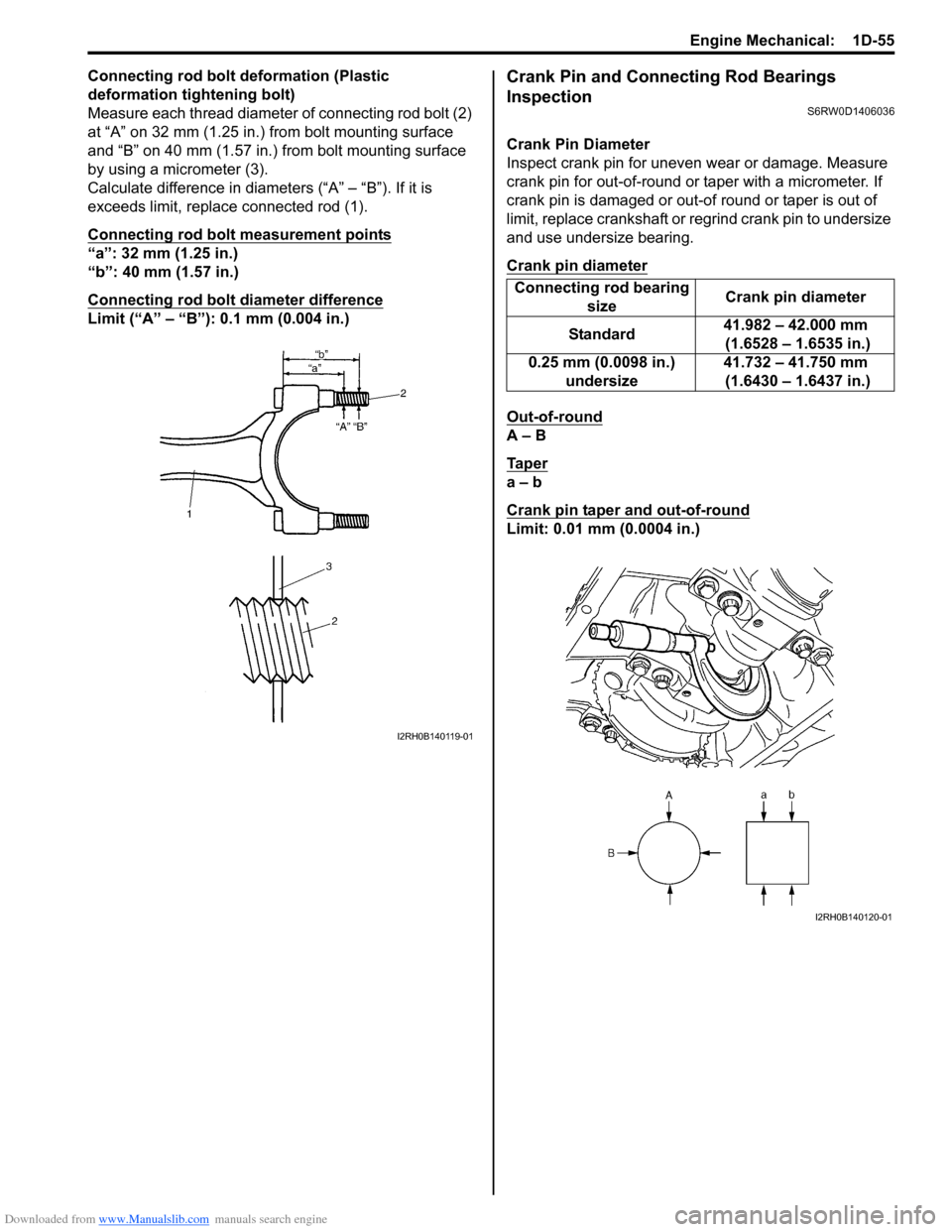
Connecting rod bolt deformation (Plastic
deformation tightening bolt)
Measure each thread diameter of connecting rod bolt (2)
at “A” on 32 mm (1.25 in.) from bolt mounting surface
and “B” on 40 mm (1.57 in.) from bolt mounting surface
by using a micrometer (3).
Calculate difference in diameters (“A” – “B”). If it is
exceeds limit, replace connected rod (1).
Connecting rod bolt measurement points
“a”: 32 mm (1.25 in.)
“b”: 40 mm (1.57 in.)
Connecting rod bolt diameter difference
Limit (“A” – “B”): 0.1 mm (0.004 in.)
Crank Pin and Connecting Rod Bearings
Inspection
S6RW0D1406036
Crank Pin Diameter
Inspect crank pin for uneven wear or damage. Measure
crank pin for out-of-round or taper with a micrometer. If
crank pin is damaged or out-of round or taper is out of
limit, replace crankshaft or regrind crank pin to undersize
and use undersize bearing.
Crank pin diameter
Out-of-round
A – B
Ta p e r
a – b
Crank pin taper and out-of-round
Limit: 0.01 mm (0.0004 in.)
I2RH0B140119-01
Connecting rod bearing
sizeCrank pin diameter
Standard41.982 – 42.000 mm
(1.6528 – 1.6535 in.)
0.25 mm (0.0098 in.)
undersize41.732 – 41.750 mm
(1.6430 – 1.6437 in.)
I2RH0B140120-01
Page 339 of 1556
Downloaded from www.Manualslib.com manuals search engine Engine Mechanical: 1D-57
Selection of Connecting Rod Bearings
NOTE
• If bearing is in malcondition, or bearing
clearance is out of specification, select a
new standard bearing according to the
following procedure and install it.
• When replacing crankshaft or connecting
rod and its bearing due to any reason,
select new standard bearings to be
installed by referring to numbers stamped
on connecting rod and its cap and/or
alphabets stamped on crank web of No.3
cylinder.
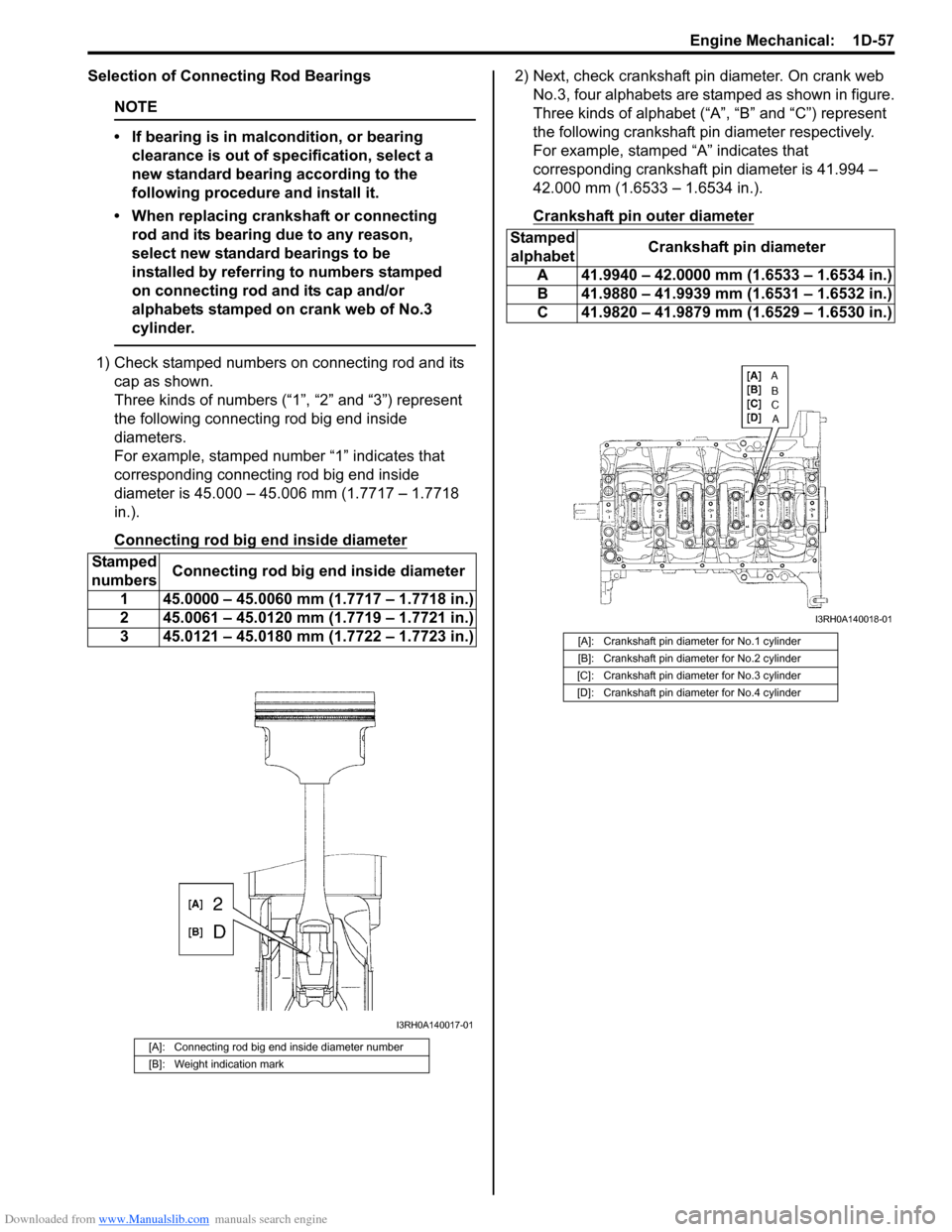
1) Check stamped numbers on connecting rod and its
cap as shown.
Three kinds of numbers (“1”, “2” and “3”) represent
the following connecting rod big end inside
diameters.
For example, stamped number “1” indicates that
corresponding connecting rod big end inside
diameter is 45.000 – 45.006 mm (1.7717 – 1.7718
in.).
Connecting rod big end inside diameter
2) Next, check crankshaft pin diameter. On crank web
No.3, four alphabets are stamped as shown in figure.
Three kinds of alphabet (“A”, “B” and “C”) represent
the following crankshaft pin diameter respectively.
For example, stamped “A” indicates that
corresponding crankshaft pin diameter is 41.994 –
42.000 mm (1.6533 – 1.6534 in.).
Crankshaft pin outer diameter
Stamped
numbersConnecting rod big end inside diameter
1 45.0000 – 45.0060 mm (1.7717 – 1.7718 in.)
2 45.0061 – 45.0120 mm (1.7719 – 1.7721 in.)
3 45.0121 – 45.0180 mm (1.7722 – 1.7723 in.)
[A]: Connecting rod big end inside diameter number
[B]: Weight indication mark
I3RH0A140017-01
Stamped
alphabetCrankshaft pin diameter
A 41.9940 – 42.0000 mm (1.6533 – 1.6534 in.)
B 41.9880 – 41.9939 mm (1.6531 – 1.6532 in.)
C 41.9820 – 41.9879 mm (1.6529 – 1.6530 in.)
[A]: Crankshaft pin diameter for No.1 cylinder
[B]: Crankshaft pin diameter for No.2 cylinder
[C]: Crankshaft pin diameter for No.3 cylinder
[D]: Crankshaft pin diameter for No.4 cylinder
I3RH0A140018-01
Page 340 of 1556
Downloaded from www.Manualslib.com manuals search engine 1D-58 Engine Mechanical:
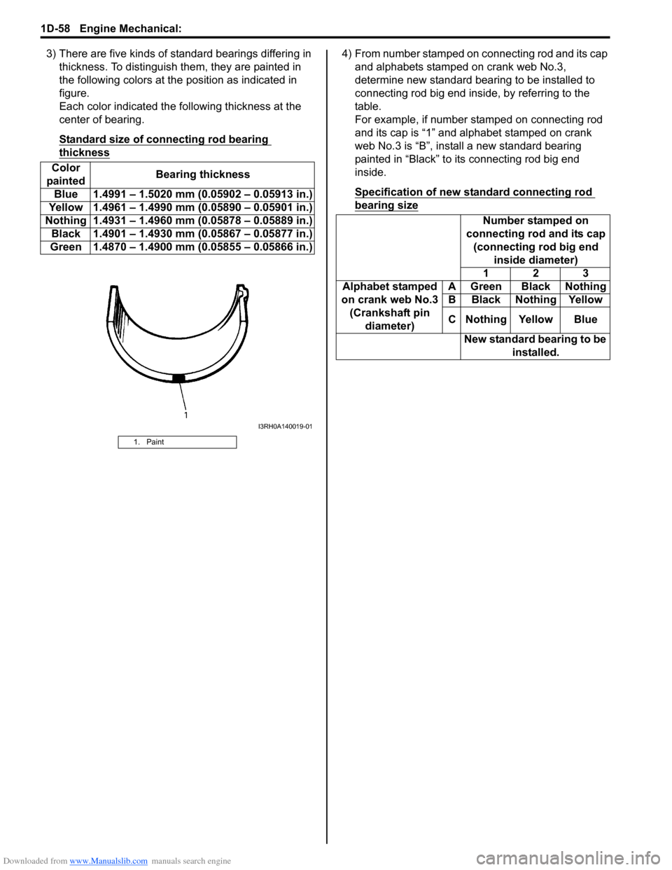
3) There are five kinds of standard bearings differing in
thickness. To distinguish them, they are painted in
the following colors at the position as indicated in
figure.
Each color indicated the following thickness at the
center of bearing.
Standard size of connecting rod bearing
thickness
4) From number stamped on connecting rod and its cap
and alphabets stamped on crank web No.3,
determine new standard bearing to be installed to
connecting rod big end inside, by referring to the
table.
For example, if number stamped on connecting rod
and its cap is “1” and alphabet stamped on crank
web No.3 is “B”, install a new standard bearing
painted in “Black” to its connecting rod big end
inside.
Specification of new standard connecting rod
bearing size
Color
paintedBearing thickness
Blue 1.4991 – 1.5020 mm (0.05902 – 0.05913 in.)
Yellow 1.4961 – 1.4990 mm (0.05890 – 0.05901 in.)
Nothing 1.4931 – 1.4960 mm (0.05878 – 0.05889 in.)
Black 1.4901 – 1.4930 mm (0.05867 – 0.05877 in.)
Green 1.4870 – 1.4900 mm (0.05855 – 0.05866 in.)
1. Paint
I3RH0A140019-01
Number stamped on
connecting rod and its cap
(connecting rod big end
inside diameter)
123
Alphabet stamped
on crank web No.3
(Crankshaft pin
diameter)A Green Black Nothing
B Black Nothing Yellow
C Nothing Yellow Blue
New standard bearing to be
installed.
Page 346 of 1556
Downloaded from www.Manualslib.com manuals search engine 1D-64 Engine Mechanical:
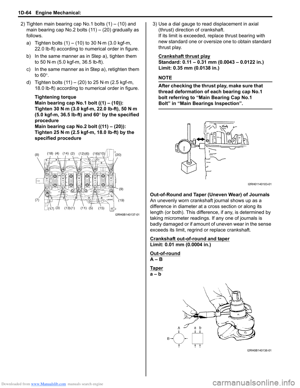
2) Tighten main bearing cap No.1 bolts (1) – (10) and
main bearing cap No.2 bolts (11) – (20) gradually as
follows.
a) Tighten bolts (1) – (10) to 30 N⋅m (3.0 kgf-m,
22.0 lb-ft) according to numerical order in figure.
b) In the same manner as in Step a), tighten them
to 50 N⋅m (5.0 kgf-m, 36.5 lb-ft).
c) In the same manner as in Step a), retighten them
to 60°.
d) Tighten bolts (11) – (20) to 25 N⋅m (2.5 kgf-m,
18.0 lb-ft) according to numerical order in figure.
Tightening torque
Main bearing cap No.1 bolt ((1) – (10)):
Tighten 30 N⋅m (3.0 kgf-m, 22.0 lb-ft), 50 N⋅m
(5.0 kgf-m, 36.5 lb-ft) and 60° by the specified
procedure
Main bearing cap No.2 bolt ((11) – (20)):
Tighten 25 N⋅m (2.5 kgf-m, 18.0 lb-ft) by the
specified procedure3) Use a dial gauge to read displacement in axial
(thrust) direction of crankshaft.
If its limit is exceeded, replace thrust bearing with
new standard one or oversize one to obtain standard
thrust play.
Crankshaft thrust play
Standard: 0.11 – 0.31 mm (0.0043 – 0.0122 in.)
Limit: 0.35 mm (0.0138 in.)
NOTE
After checking the thrust play, make sure that
thread deformation of each bearing cap No.1
bolt referring to “Main Bearing Cap No.1
Bolt” in “Main Bearings Inspection”.
Out-of-Round and Taper (Uneven Wear) of Journals
An unevenly worn crankshaft journal shows up as a
difference in diameter at a cross section or along its
length (or both). This difference, if any, is determined by
taking micrometer readings. If any one of journals is
badly damaged or if amount of uneven wear in the sense
exceeds its limit, regrind or replace crankshaft.
Crankshaft out-of-round and taper
Limit: 0.01 mm (0.0004 in.)
Out-of-round
A – B
Ta p e r
a – b
I2RH0B140137-01
I2RH01140183-01
I2RH0B140138-01
Page 348 of 1556
Downloaded from www.Manualslib.com manuals search engine 1D-66 Engine Mechanical:
Selection of Main Bearings
Standard bearing
If bearing is in malcondition, or bearing clearance is out
of specification, select a new standard bearing according
to the following procedure and install it.
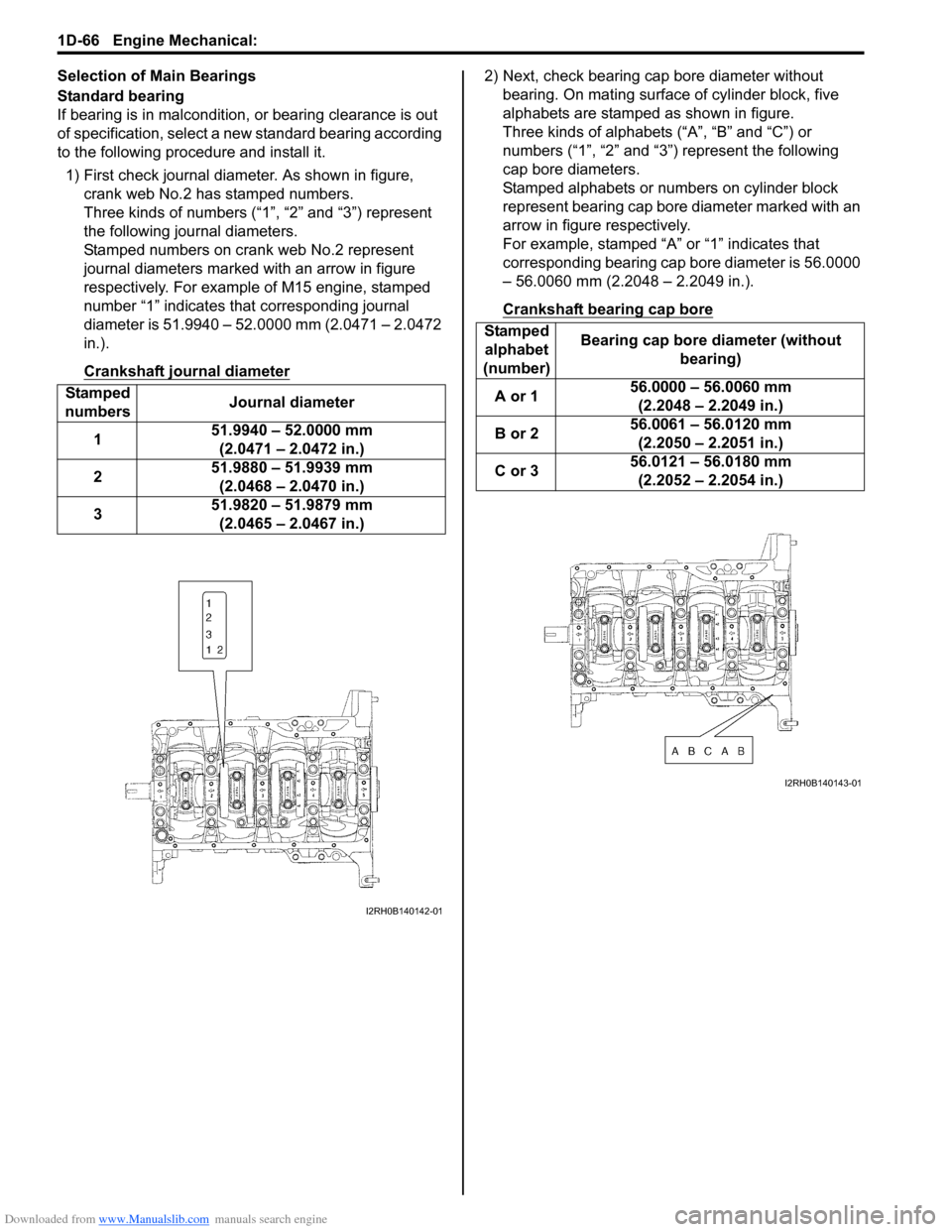
1) First check journal diameter. As shown in figure,
crank web No.2 has stamped numbers.
Three kinds of numbers (“1”, “2” and “3”) represent
the following journal diameters.
Stamped numbers on crank web No.2 represent
journal diameters marked with an arrow in figure
respectively. For example of M15 engine, stamped
number “1” indicates that corresponding journal
diameter is 51.9940 – 52.0000 mm (2.0471 – 2.0472
in.).
Crankshaft journal diameter2) Next, check bearing cap bore diameter without
bearing. On mating surface of cylinder block, five
alphabets are stamped as shown in figure.
Three kinds of alphabets (“A”, “B” and “C”) or
numbers (“1”, “2” and “3”) represent the following
cap bore diameters.
Stamped alphabets or numbers on cylinder block
represent bearing cap bore diameter marked with an
arrow in figure respectively.
For example, stamped “A” or “1” indicates that
corresponding bearing cap bore diameter is 56.0000
– 56.0060 mm (2.2048 – 2.2049 in.).
Crankshaft bearing cap bore
Stamped
numbersJournal diameter
151.9940 – 52.0000 mm
(2.0471 – 2.0472 in.)
251.9880 – 51.9939 mm
(2.0468 – 2.0470 in.)
351.9820 – 51.9879 mm
(2.0465 – 2.0467 in.)
I2RH0B140142-01
Stamped
alphabet
(number)Bearing cap bore diameter (without
bearing)
A or 156.0000 – 56.0060 mm
(2.2048 – 2.2049 in.)
B or 256.0061 – 56.0120 mm
(2.2050 – 2.2051 in.)
C or 356.0121 – 56.0180 mm
(2.2052 – 2.2054 in.)
I2RH0B140143-01
Page 349 of 1556
Downloaded from www.Manualslib.com manuals search engine Engine Mechanical: 1D-67
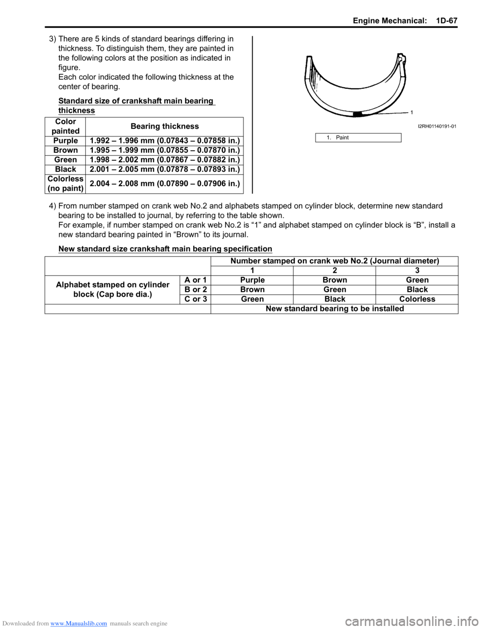
3) There are 5 kinds of standard bearings differing in
thickness. To distinguish them, they are painted in
the following colors at the position as indicated in
figure.
Each color indicated the following thickness at the
center of bearing.
Standard size of crankshaft main bearing
thickness
4) From number stamped on crank web No.2 and alphabets stamped on cylinder block, determine new standard
bearing to be installed to journal, by referring to the table shown.
For example, if number stamped on crank web No.2 is “1” and alphabet stamped on cylinder block is “B”, install a
new standard bearing painted in “Brown” to its journal.
New standard size crankshaft main bearing specification
Color
paintedBearing thickness
Purple 1.992 – 1.996 mm (0.07843 – 0.07858 in.)
Brown 1.995 – 1.999 mm (0.07855 – 0.07870 in.)
Green 1.998 – 2.002 mm (0.07867 – 0.07882 in.)
Black 2.001 – 2.005 mm (0.07878 – 0.07893 in.)
Colorless
(no paint)2.004 – 2.008 mm (0.07890 – 0.07906 in.)
1. Paint
I2RH01140191-01
Number stamped on crank web No.2 (Journal diameter)
123
Alphabet stamped on cylinder
block (Cap bore dia.)A or 1 Purple Brown Green
B or 2 Brown Green Black
C or 3 Green Black Colorless
New standard bearing to be installed