meter SUZUKI SX4 2006 1.G Service Repair Manual
[x] Cancel search | Manufacturer: SUZUKI, Model Year: 2006, Model line: SX4, Model: SUZUKI SX4 2006 1.GPages: 1556, PDF Size: 37.31 MB
Page 351 of 1556
Downloaded from www.Manualslib.com manuals search engine Engine Mechanical: 1D-69
• If necessary, regrind crankshaft journal and select undersize bearing to use with it as follows.
a. Regrind journal to the following finished diameter.
Finished journal diameter
51.7320 – 51.7500 mm (2.0367 – 2.0374 in.)
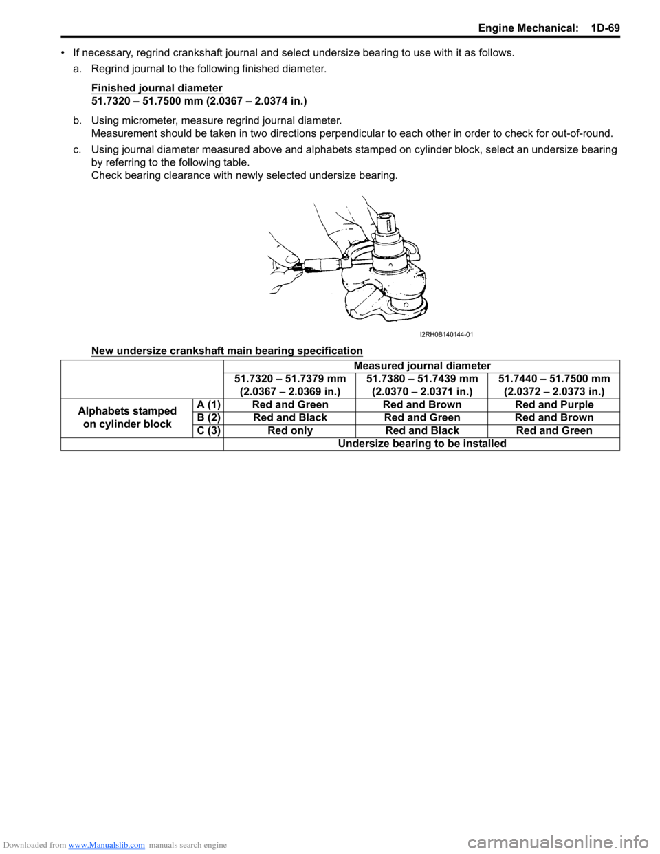
b. Using micrometer, measure regrind journal diameter.
Measurement should be taken in two directions perpendicular to each other in order to check for out-of-round.
c. Using journal diameter measured above and alphabets stamped on cylinder block, select an undersize bearing
by referring to the following table.
Check bearing clearance with newly selected undersize bearing.
New undersize crankshaft main bearing specification
Measured journal diameter
51.7320 – 51.7379 mm
(2.0367 – 2.0369 in.)51.7380 – 51.7439 mm
(2.0370 – 2.0371 in.)51.7440 – 51.7500 mm
(2.0372 – 2.0373 in.)
Alphabets stamped
on cylinder blockA (1) Red and Green Red and Brown Red and Purple
B (2) Red and Black Red and Green Red and Brown
C (3) Red only Red and Black Red and Green
Undersize bearing to be installed
I2RH0B140144-01
Page 352 of 1556
Downloaded from www.Manualslib.com manuals search engine 1D-70 Engine Mechanical:
Main Bearing Cap No.1 Bolt
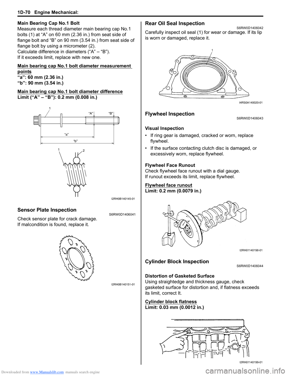
Measure each thread diameter main bearing cap No.1
bolts (1) at “A” on 60 mm (2.36 in.) from seat side of
flange bolt and “B” on 90 mm (3.54 in.) from seat side of
flange bolt by using a micrometer (2).
Calculate difference in diameters (“A” – “B”).
If it exceeds limit, replace with new one.
Main bearing cap No.1 bolt diameter measurement
points
“a”: 60 mm (2.36 in.)
“b”: 90 mm (3.54 in.)
Main bearing cap No.1 bolt diameter difference
Limit (“A” – “B”): 0.2 mm (0.008 in.)
Sensor Plate InspectionS6RW0D1406041
Check sensor plate for crack damage.
If malcondition is found, replace it.
Rear Oil Seal InspectionS6RW0D1406042
Carefully inspect oil seal (1) for wear or damage. If its lip
is worn or damaged, replace it.
Flywheel InspectionS6RW0D1406043
Visual Inspection
• If ring gear is damaged, cracked or worn, replace
flywheel.
• If the surface contacting clutch disc is damaged, or
excessively worn, replace flywheel.
Flywheel Face Runout
Check flywheel face runout with a dial gauge.
If runout exceeds its limit, replace flywheel.
Flywheel face runout
Limit: 0.2 mm (0.0079 in.)
Cylinder Block InspectionS6RW0D1406044
Distortion of Gasketed Surface
Using straightedge and thickness gauge, check
gasketed surface for distortion and, if flatness exceeds
its limit, correct It.
Cylinder block flatness
Limit: 0.03 mm (0.0012 in.)
“A”
“a”
“b”“B”
1
1
2
I2RH0B140145-01
I2RH0B140151-01
I4RS0A140020-01
I2RH01140198-01
I2RH01140199-01
Page 353 of 1556
Downloaded from www.Manualslib.com manuals search engine Engine Mechanical: 1D-71
Honing or Reboring Cylinders
1) When any cylinder needs reboring, all other
cylinders must also be rebored at the same time.
2) Select oversized piston according to amount of
cylinder wear.
Oversize piston specification
Oversize 0.50: 78.453 – 78.468 mm (3.0887 –
3.0893 in.)
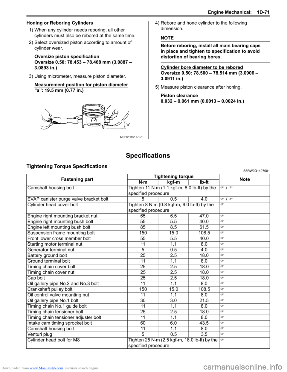
3) Using micrometer, measure piston diameter.
Measurement position for piston diameter
“a”: 19.5 mm (0.77 in.)4) Rebore and hone cylinder to the following
dimension.
NOTE
Before reboring, install all main bearing caps
in place and tighten to specification to avoid
distortion of bearing bores.
Cylinder bore diameter to be rebored
Oversize 0.50: 78.500 – 78.514 mm (3.0906 –
3.0911 in.)
5) Measure piston clearance after honing.
Piston clearance
0.032 – 0.061 mm (0.0013 – 0.0024 in.)
Specifications
Tightening Torque SpecificationsS6RW0D1407001
I2RH01140157-01
Fastening partTightening torque
Note
N⋅mkgf-mlb-ft
Camshaft housing bolt Tighten 11 N⋅m (1.1 kgf-m, 8.0 lb-ft) by the
specified procedure�) / �)
EVAP canister purge valve bracket bolt 5 0.5 4.0�) / �)
Cylinder head cover bolt Tighten 8 N⋅m (0.8 kgf-m, 6.0 lb-ft) by the
specified procedure�)
Engine right mounting bracket nut 65 6.5 47.0�)
Engine right mounting bush bolt 55 5.5 40.0�)
Engine left mounting bush bolt 85 8.5 61.5�)
Suspension frame mounting bolt 150 15.0 108.5�)
Front lower cross member bolt 55 5.5 40.0�)
Starting motor terminal nut 11 1.1 8.0�)
Generator terminal nut 5 0.5 4.0�)
Battery ground bolt 25 2.5 18.0�)
Ground terminal bolt 11 1.1 8.0�)
Timing chain cover bolt 25 2.5 18.0�)
Timing chain cover nut 25 2.5 18.0�)
Cap bolt 25 2.5 18.0�)
Oil gallery pipe No.2 and No.3 bolt 11 1.1 8.0�)
Crankshaft pulley bolt 150 15.0 108.5�)
Oil control valve mounting nut 11 1.1 8.0�)
Oil gallery pipe No.1 bolt 30 3.0 21.5�)
Timing chain No.1 guide bolt 11 1.1 8.0�)
Timing chain tensioner bolt 25 2.5 18.0�)
Timing chain tensioner adjuster bolt 11 1.1 8.0�)
Intake cam timing sprocket bolt 60 6.0 43.5�)
Camshaft housing bolt 11 1.1 8.0�)
Venturi plug 5 0.5 3.5�)
Cylinder head bolt for M8 Tighten 25 N⋅m (2.5 kgf-m, 18.0 lb-ft) by the
specified procedure�)
Page 372 of 1556
Downloaded from www.Manualslib.com manuals search engine 1F-7 Engine Cooling System:
Thermostat Removal and InstallationS6RW0D1606007
Removal
1) Drain coolant referring to “Cooling System Draining”.
2) Remove intake manifold referring to “Intake Manifold
Removal and Installation in Section 1D”.
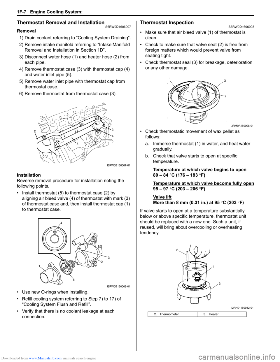
3) Disconnect water hose (1) and heater hose (2) from
each pipe.
4) Remove thermostat case (3) with thermostat cap (4)
and water inlet pipe (5).
5) Remove water inlet pipe with thermostat cap from
thermostat case.
6) Remove thermostat from thermostat case (3).
Installation
Reverse removal procedure for installation noting the
following points.
• Install thermostat (5) to thermostat case (2) by
aligning air bleed valve (4) of thermostat with mark (3)
of thermostat case and, then install thermostat cap (1)
to thermostat case.
• Use new O-rings when installing.
• Refill cooling system referring to Step 7) to 17) of
“Cooling System Flush and Refill”.
• Verify that there is no coolant leakage at each
connection.
Thermostat InspectionS6RW0D1606008
• Make sure that air bleed valve (1) of thermostat is
clean.
• Check to make sure that valve seat (2) is free from
foreign matters which would prevent valve from
seating tight.
• Check thermostat seal (3) for breakage, deterioration
or any other damage.
• Check thermostatic movement of wax pellet as
follows:
a. Immerse thermostat (1) in water, and heat water
gradually.
b. Check that valve starts to open at specific
temperature.
Temperature at which valve begins to open
80 – 84 °C (176 – 183 °F)
Temperature at which valve become fully open
95 – 97 °C (203 – 206 °F)
Va l v e l i ft
More than 8 mm (0.31 in.) at 95 °C (203 °F)
If valve starts to open at a temperature substantially
below or above specific temperature, thermostat unit
should be replaced with a new one. Such a unit, if
reused, will bring about overcooling or overheating
tendency.
I6RW0B160007-01
4
53
12
I6RW0B160008-01
2. Thermometer 3. Heater
I3RM0A160008-01
I2RH01160012-01
Page 386 of 1556
Downloaded from www.Manualslib.com manuals search engine 1G-9 Fuel System:
Fuel Injector On-Vehicle InspectionS6RW0D1706007
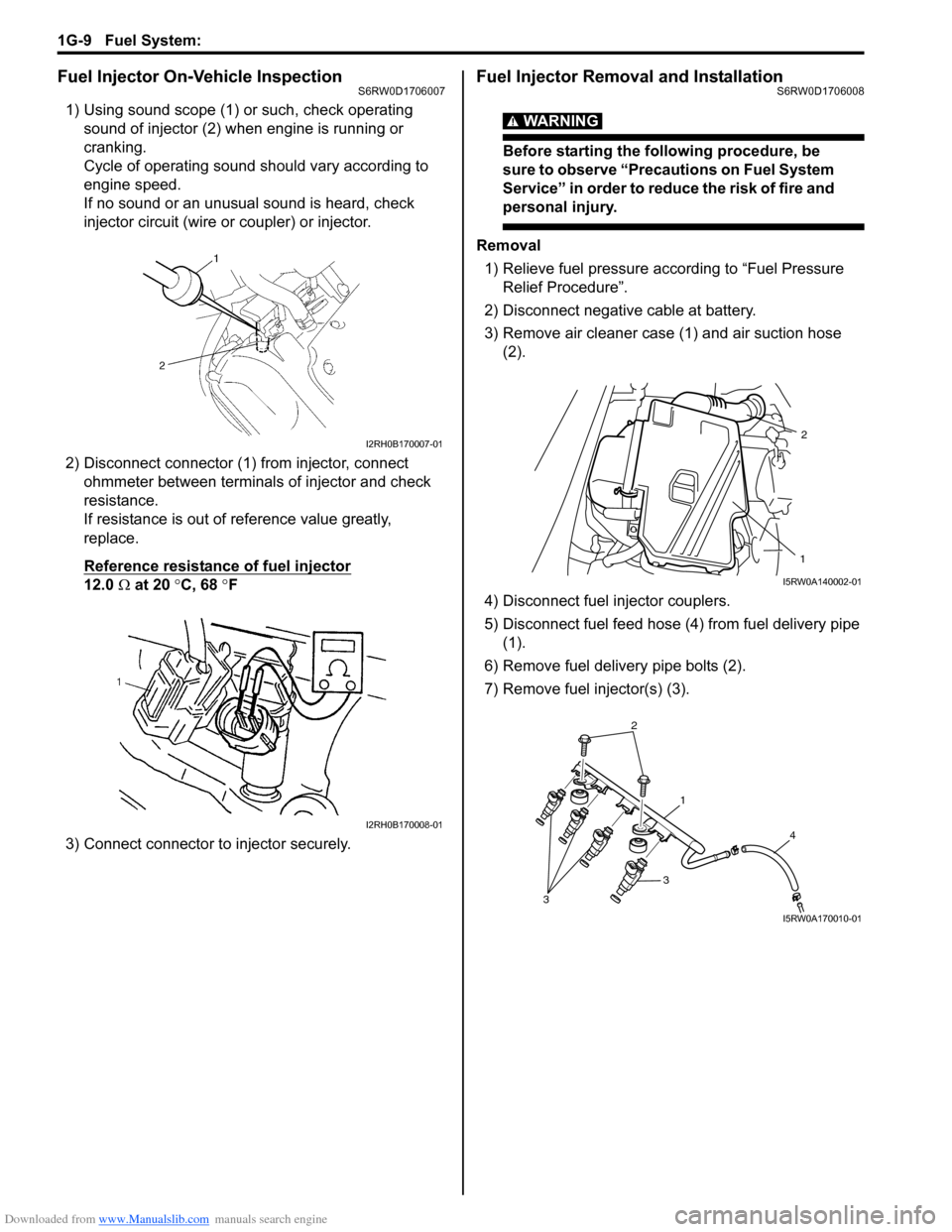
1) Using sound scope (1) or such, check operating
sound of injector (2) when engine is running or
cranking.
Cycle of operating sound should vary according to
engine speed.
If no sound or an unusual sound is heard, check
injector circuit (wire or coupler) or injector.
2) Disconnect connector (1) from injector, connect
ohmmeter between terminals of injector and check
resistance.
If resistance is out of reference value greatly,
replace.
Reference resistance of fuel injector
12.0 Ω at 20 °C, 68 °F
3) Connect connector to injector securely.
Fuel Injector Removal and InstallationS6RW0D1706008
WARNING!
Before starting the following procedure, be
sure to observe “Precautions on Fuel System
Service” in order to reduce the risk of fire and
personal injury.
Removal
1) Relieve fuel pressure according to “Fuel Pressure
Relief Procedure”.
2) Disconnect negative cable at battery.
3) Remove air cleaner case (1) and air suction hose
(2).
4) Disconnect fuel injector couplers.
5) Disconnect fuel feed hose (4) from fuel delivery pipe
(1).
6) Remove fuel delivery pipe bolts (2).
7) Remove fuel injector(s) (3).
I2RH0B170007-01
I2RH0B170008-01
1
2
I5RW0A140002-01
2
1
4
3
3
I5RW0A170010-01
Page 387 of 1556
Downloaded from www.Manualslib.com manuals search engine Fuel System: 1G-10
Installation
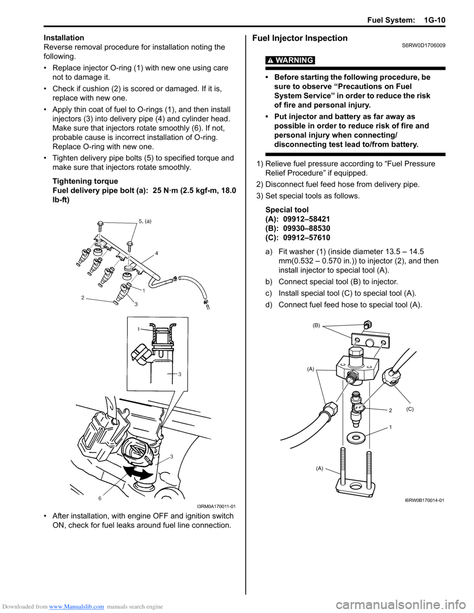
Reverse removal procedure for installation noting the
following.
• Replace injector O-ring (1) with new one using care
not to damage it.
• Check if cushion (2) is scored or damaged. If it is,
replace with new one.
• Apply thin coat of fuel to O-rings (1), and then install
injectors (3) into delivery pipe (4) and cylinder head.
Make sure that injectors rotate smoothly (6). If not,
probable cause is incorrect installation of O-ring.
Replace O-ring with new one.
• Tighten delivery pipe bolts (5) to specified torque and
make sure that injectors rotate smoothly.
Tightening torque
Fuel delivery pipe bolt (a): 25 N·m (2.5 kgf-m, 18.0
lb-ft)
• After installation, with engine OFF and ignition switch
ON, check for fuel leaks around fuel line connection.Fuel Injector InspectionS6RW0D1706009
WARNING!
• Before starting the following procedure, be
sure to observe “Precautions on Fuel
System Service” in order to reduce the risk
of fire and personal injury.
• Put injector and battery as far away as
possible in order to reduce risk of fire and
personal injury when connecting/
disconnecting test lead to/from battery.
1) Relieve fuel pressure according to “Fuel Pressure
Relief Procedure” if equipped.
2) Disconnect fuel feed hose from delivery pipe.
3) Set special tools as follows.
Special tool
(A): 09912–58421
(B): 09930–88530
(C): 09912–57610
a) Fit washer (1) (inside diameter 13.5 – 14.5
mm(0.532 – 0.570 in.)) to injector (2), and then
install injector to special tool (A).
b) Connect special tool (B) to injector.
c) Install special tool (C) to special tool (A).
d) Connect fuel feed hose to special tool (A).
I3RM0A170011-01
(B)
(A)
(A)(C)
2
1
I6RW0B170014-01
Page 395 of 1556

Downloaded from www.Manualslib.com manuals search engine Fuel System: 1G-18
Special Tools and Equipment
Special ToolS6RW0D1708001
09912–57610 09912–58421
Injector checking tool plate Checking tool set
�)This kit includes the
following items. 1. Tool body
and washer, 2. Body plug, 3.
Body attachment-1, 4.
Holder, 5. Return hose and
clamp, 6. Body attachment-2
and washer, 7. Hose
attachment-1, 8. Hose
attachment-2 �)
09912–58432 09912–58442
Fuel pressure gauge hose Fuel pressure gauge
This tool is included in fuel
pressure gauge set (09912-
58413). �)This tool is included in fuel
pressure gauge set (09912-
58413). �)
09912–58490 09919–47020
3-way joint & hose Quick joint remover
�)�)
09930–88530 SUZUKI scan tool (SUZUKI-
SDT)
Injector test lead —
�)This kit includes following
items. 1. SUZUKI-SDT 2.
DLC3 cable 3. USB cable 4.
AC/DC power supply 5.
Voltage meter probe 6.
Storage case �)
1
2
34
56
Page 402 of 1556
Downloaded from www.Manualslib.com manuals search engine 1H-7 Ignition System:
High-Tension Cord InspectionS6RW0D1806002
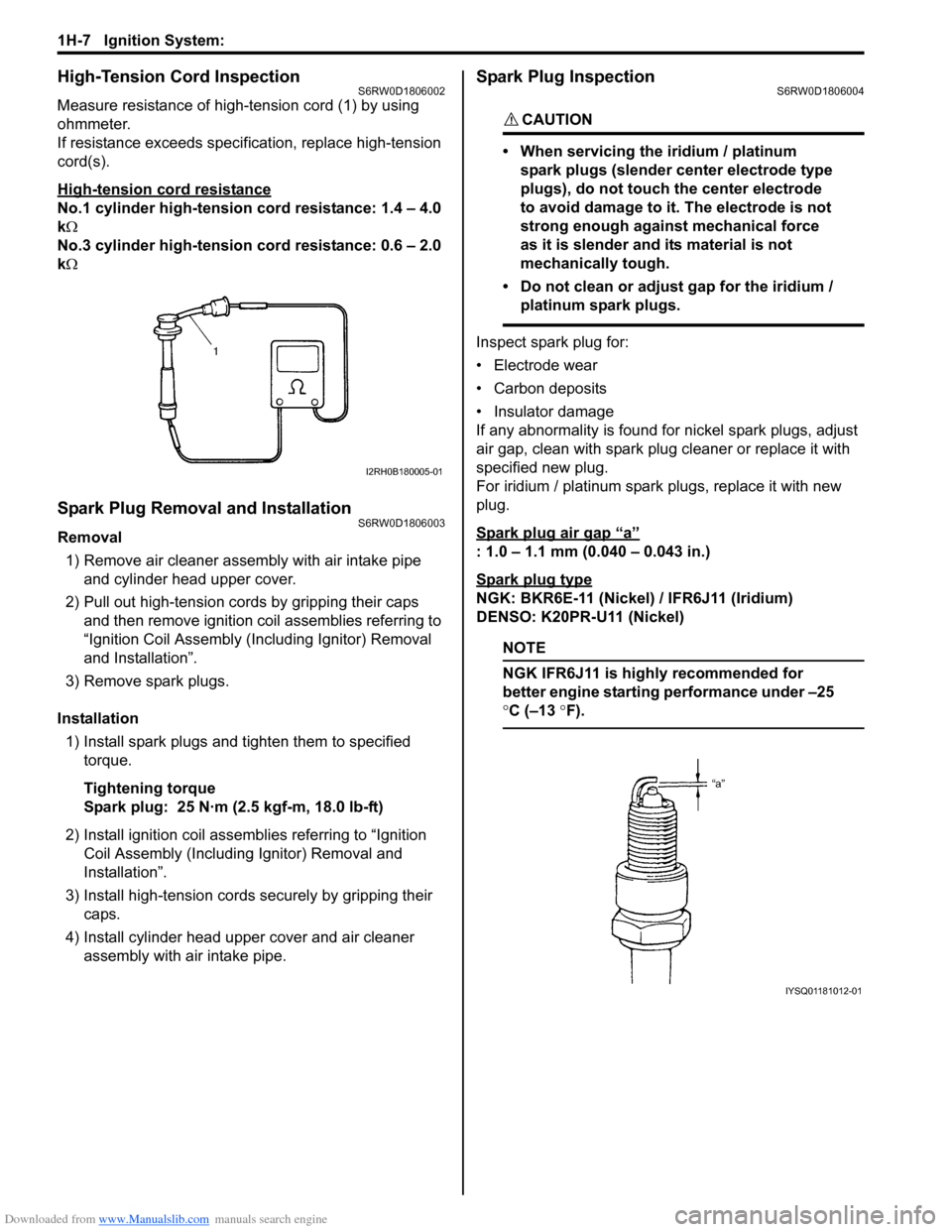
Measure resistance of high-tension cord (1) by using
ohmmeter.
If resistance exceeds specification, replace high-tension
cord(s).
High-tension cord resistance
No.1 cylinder high-tension cord resistance: 1.4 – 4.0
kΩ
No.3 cylinder high-tension cord resistance: 0.6 – 2.0
kΩ
Spark Plug Removal and InstallationS6RW0D1806003
Removal
1) Remove air cleaner assembly with air intake pipe
and cylinder head upper cover.
2) Pull out high-tension cords by gripping their caps
and then remove ignition coil assemblies referring to
“Ignition Coil Assembly (Including Ignitor) Removal
and Installation”.
3) Remove spark plugs.
Installation
1) Install spark plugs and tighten them to specified
torque.
Tightening torque
Spark plug: 25 N·m (2.5 kgf-m, 18.0 lb-ft)
2) Install ignition coil assemblies referring to “Ignition
Coil Assembly (Including Ignitor) Removal and
Installation”.
3) Install high-tension cords securely by gripping their
caps.
4) Install cylinder head upper cover and air cleaner
assembly with air intake pipe.
Spark Plug InspectionS6RW0D1806004
CAUTION!
• When servicing the iridium / platinum
spark plugs (slender center electrode type
plugs), do not touch the center electrode
to avoid damage to it. The electrode is not
strong enough against mechanical force
as it is slender and its material is not
mechanically tough.
• Do not clean or adjust gap for the iridium /
platinum spark plugs.
Inspect spark plug for:
• Electrode wear
• Carbon deposits
• Insulator damage
If any abnormality is found for nickel spark plugs, adjust
air gap, clean with spark plug cleaner or replace it with
specified new plug.
For iridium / platinum spark plugs, replace it with new
plug.
Spark plug air gap
“a”
: 1.0 – 1.1 mm (0.040 – 0.043 in.)
Spark plug type
NGK: BKR6E-11 (Nickel) / IFR6J11 (Iridium)
DENSO: K20PR-U11 (Nickel)
NOTE
NGK IFR6J11 is highly recommended for
better engine starting performance under –25
°C (–13 °F).
I2RH0B180005-01
IYSQ01181012-01
Page 405 of 1556
Downloaded from www.Manualslib.com manuals search engine Ignition System: 1H-10
Specifications
Tightening Torque SpecificationsS6RW0D1807001
Reference:
For the tightening torque of fastener not specified in this section, refer to “Fasteners Information in Section 0A”.
Special Tools and Equipment
Special ToolS6RW0D1808001
Fastening partTightening torque
Note
N⋅mkgf-mlb-ft
Spark plug 25 2.5 18.0�)
Ignition coil bolt 11 1.1 8.0�)
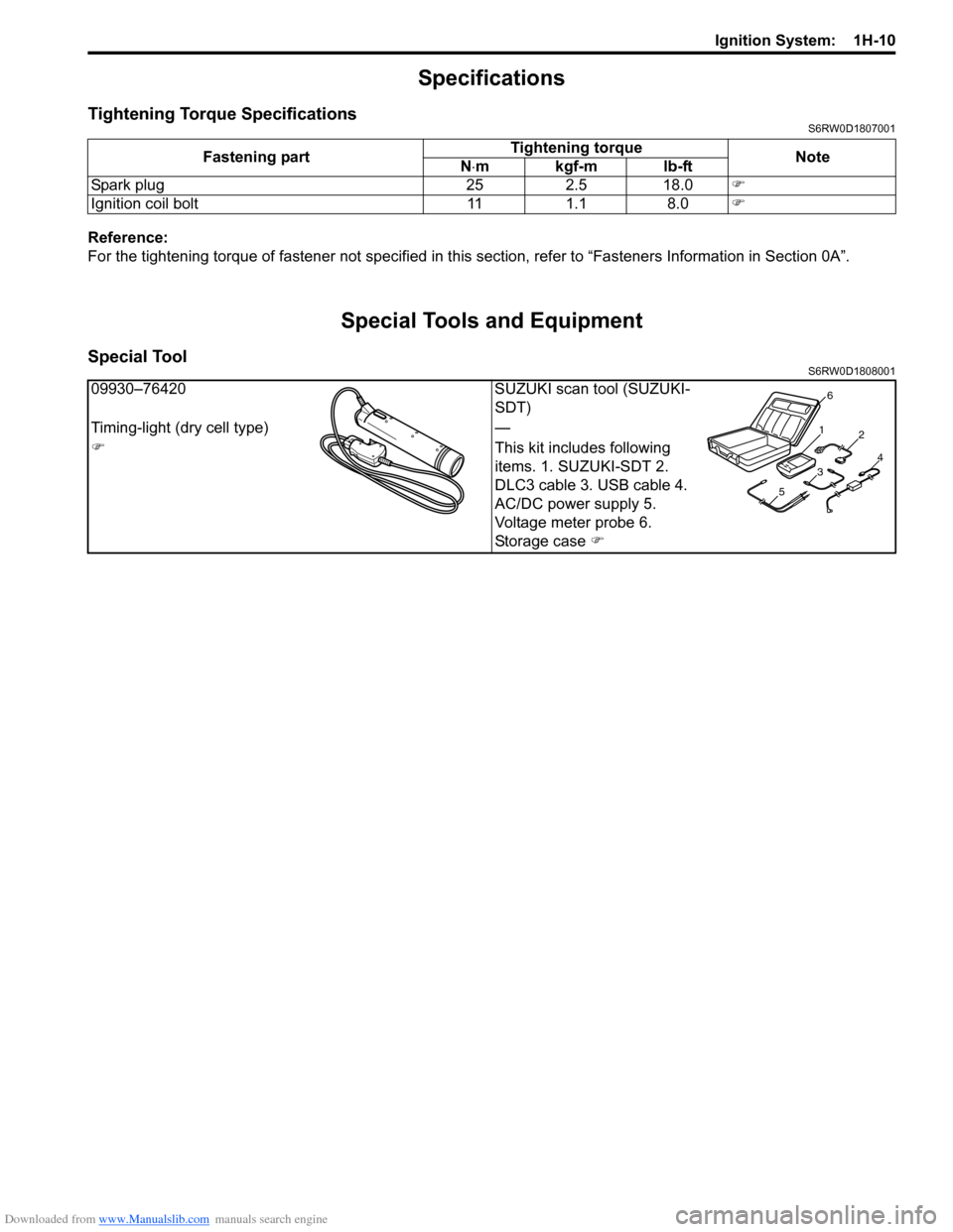
09930–76420 SUZUKI scan tool (SUZUKI-
SDT)
Timing-light (dry cell type) —
�)This kit includes following
items. 1. SUZUKI-SDT 2.
DLC3 cable 3. USB cable 4.
AC/DC power supply 5.
Voltage meter probe 6.
Storage case �)
1
2
34
56
Page 408 of 1556
Downloaded from www.Manualslib.com manuals search engine 1I-3 Starting System:
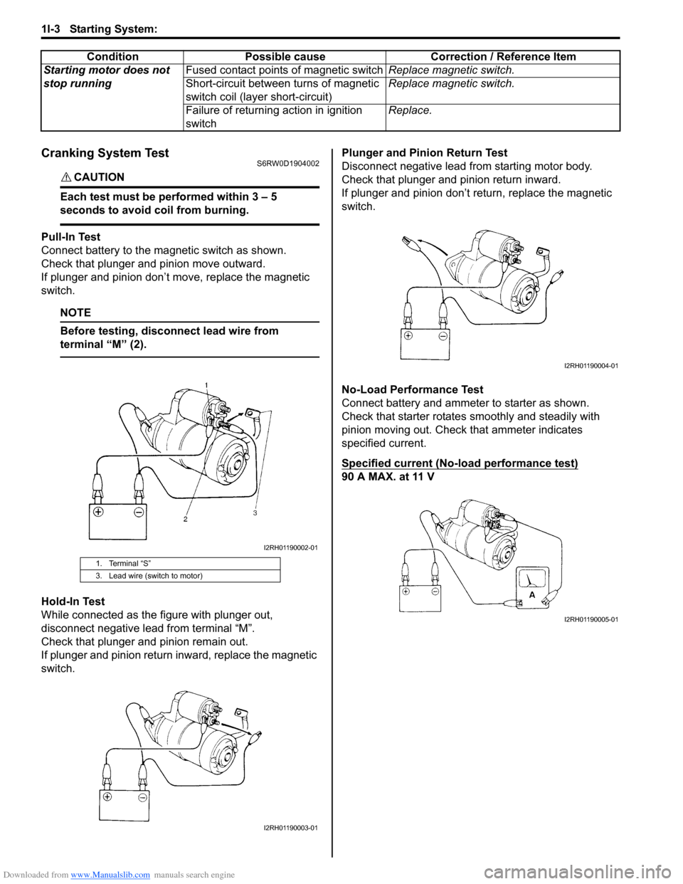
Cranking System TestS6RW0D1904002
CAUTION!
Each test must be performed within 3 – 5
seconds to avoid coil from burning.
Pull-In Test
Connect battery to the magnetic switch as shown.
Check that plunger and pinion move outward.
If plunger and pinion don’t move, replace the magnetic
switch.
NOTE
Before testing, disconnect lead wire from
terminal “M” (2).
Hold-In Test
While connected as the figure with plunger out,
disconnect negative lead from terminal “M”.
Check that plunger and pinion remain out.
If plunger and pinion return inward, replace the magnetic
switch.Plunger and Pinion Return Test
Disconnect negative lead from starting motor body.
Check that plunger and pinion return inward.
If plunger and pinion don’t return, replace the magnetic
switch.
No-Load Performance Test
Connect battery and ammeter to starter as shown.
Check that starter rotates smoothly and steadily with
pinion moving out. Check that ammeter indicates
specified current.
Specified current (No-load performance test)
90 A MAX. at 11 V Starting motor does not
stop runningFused contact points of magnetic switchReplace magnetic switch.
Short-circuit between turns of magnetic
switch coil (layer short-circuit)Replace magnetic switch.
Failure of returning action in ignition
switchReplace. Condition Possible cause Correction / Reference Item
1. Terminal “S”
3. Lead wire (switch to motor)
I2RH01190002-01
I2RH01190003-01
I2RH01190004-01
I2RH01190005-01