engine and emission control check SUZUKI SX4 2006 1.G Service Repair Manual
[x] Cancel search | Manufacturer: SUZUKI, Model Year: 2006, Model line: SX4, Model: SUZUKI SX4 2006 1.GPages: 1556, PDF Size: 37.31 MB
Page 200 of 1556

Downloaded from www.Manualslib.com manuals search engine 1A-150 Engine General Information and Diagnosis:
DTC Troubleshooting
NOTE
Before this troubleshooting is performed, read the precautions for DTC troubleshooting referring to
“Precautions for DTC Troubleshooting”.
Step Action Yes No
1Was “Engine and Emission Control System Check”
performed?Go to Step 2. Go to “Engine and
Emission Control
System Check”.
2Electric throttle body assembly system check
1) Connect scan tool to DLC with ignition switch turned
OFF.
2) Turn ON ignition switch, check each voltage of “TP
Sensor 1 Volt” and “TP Sensor 2 Volt” displayed on scan
tool when accelerator pedal is idle position and fully
depressed.
Is displayed each TP sensor value as described voltage in
“Scan Tool Data”?Intermittent trouble.
Check for intermittent
referring to “Intermittent
and Poor Connection
Inspection in Section
00”.Go to Step 3.
3Throttle actuator circuit check
1) Disconnect connector from electric throttle body
assembly with ignition switch turned OFF.
2) Check for proper connection to electric throttle body
assembly at “BLU” and “YEL” wire terminals.
3) Disconnect connectors from ECM.
4) Check for proper connection to ECM at “C01-45” and
“C01-44” terminals.
5) Measure resistance at following connector terminals.
• Between “BLU” wire terminal of electric throttle body
assembly connector and “C01-45” terminal of ECM
connector
• Between “YEL” wire terminal of electric throttle body
assembly connector and “C01-44” terminal of ECM
connector
Is each resistance below 5
Ω?Go to Step 4. “BLU” wire and/or “YEL”
wire is open or high
resistance.
4Electric throttle body assembly check
1) Check electric throttle body assembly referring to
“Electric Throttle Body Assembly and Its Circuit Check”
under “Electric Throttle Body Assembly On-Vehicle
Inspection in Section 1C”.
Is check result satisfactory?Substitute a known-
good ECM and recheck.Replace electric throttle
body assembly.
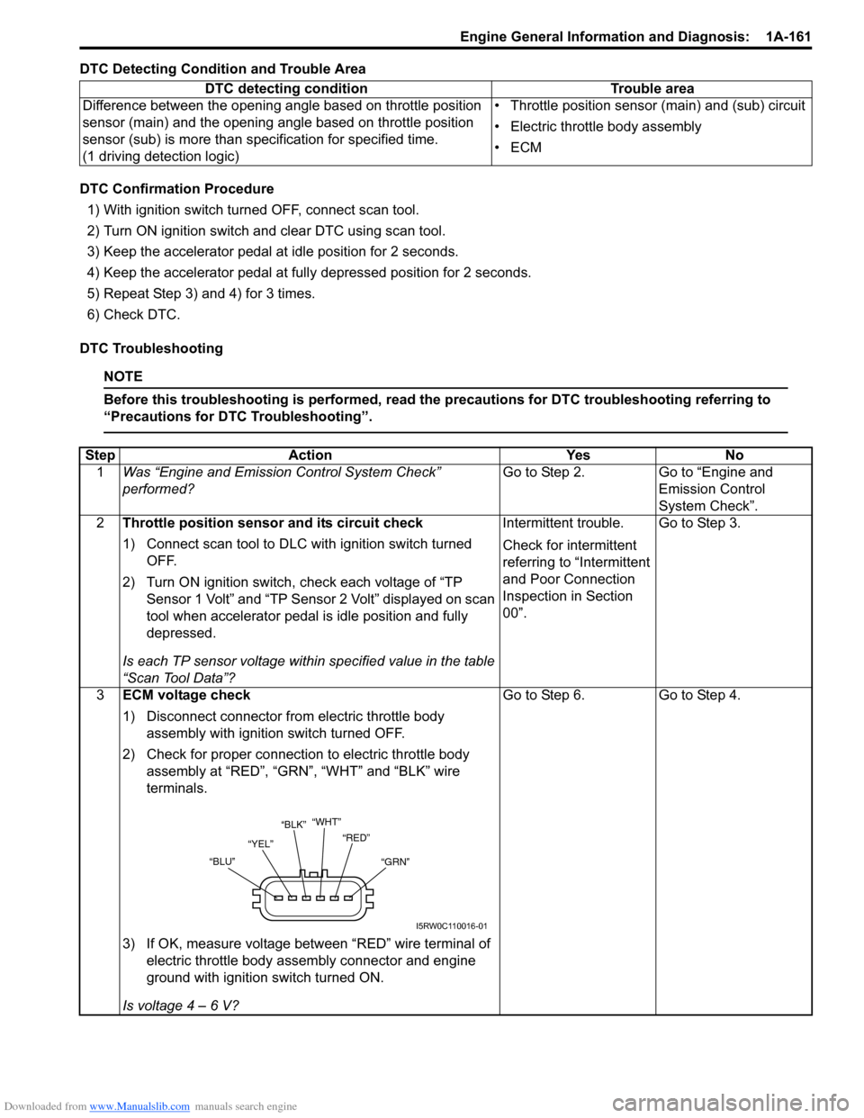
“WHT”
“YEL”“RED”
“GRN” “BLU”“BLK”
I5RW0C110016-01
Page 202 of 1556

Downloaded from www.Manualslib.com manuals search engine 1A-152 Engine General Information and Diagnosis:
DTC Troubleshooting
NOTE
Before this troubleshooting is performed, read the precautions for DTC troubleshooting referring to
“Precautions for DTC Troubleshooting”.
Step Action Yes No
1Was “Engine and Emission Control System Check”
performed?Go to Step 2. Go to “Engine and
Emission Control
System Check”.
2APP sensor assembly mounting check
1) Check that APP sensor assembly has been mounted to
vehicle body properly (no pinched floor carpet, etc.).
Is it OK?Go to Step 3. Reinstall APP sensor
assembly properly
referring to “Accelerator
Pedal Position (APP)
Sensor Assembly
Removal and
Installation in Section
1C”.
3APP sensor (main) and its circuit check
1) Connect scan tool to DLC with ignition switch turned
OFF.
2) Turn ON ignition switch, check “APP Sensor 1 Volt”
displayed on scan tool.
Is displayed voltage below 0.167 V?Go to Step 4. Intermittent trouble.
Check for intermittent
referring to “Intermittent
and Poor Connection
Inspection in Section
00”.
4ECM voltage check
1) Disconnect connector from APP sensor assembly with
ignition switch turned OFF.
2) Check for proper connection to APP sensor assembly at
“BRN”, “GRN” and “BLU” wire terminals.
3) If OK, measure voltage between “BRN” wire terminal of
APP sensor assembly connector and vehicle body
ground with ignition switch turned ON.
Is voltage 4 – 6 V?Go to Step 7. Go to Step 5.
5ECM voltage check
1) Turn OFF ignition switch.
2) Remove ECM from its bracket with ECM connectors
connected.
3) Check for proper connection of ECM connector at “E01-
35” terminal.
4) If OK, measure voltage between “E01-35” terminal of
ECM connector and engine ground with ignition switch
turned ON.
Is voltage 4 – 6 V?“BRN” wire is open or
high resistance circuit.Go to Step 6.
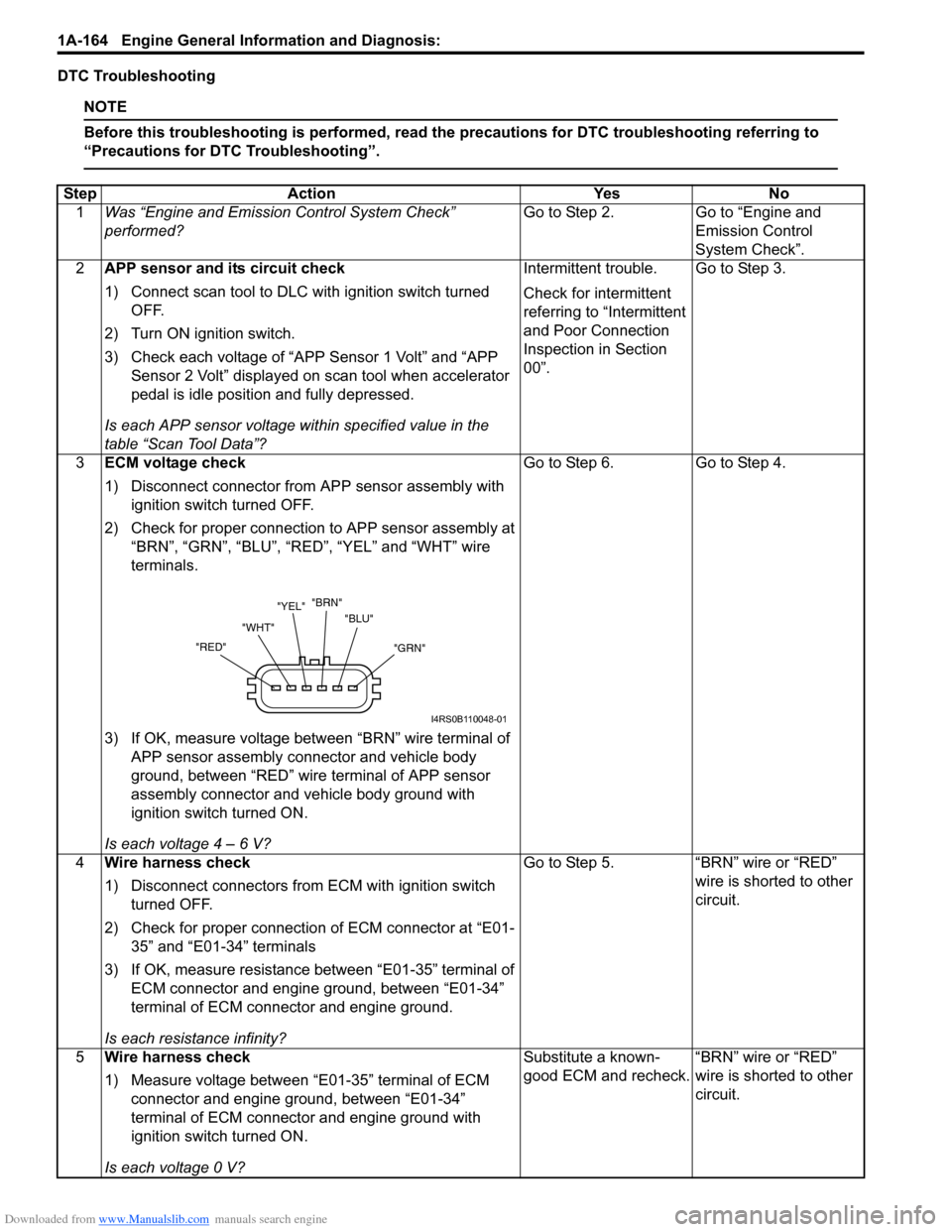
"GRN" "BLU" "BRN"
"YEL"
"WHT"
"RED"
I4RS0B110048-01
Page 204 of 1556

Downloaded from www.Manualslib.com manuals search engine 1A-154 Engine General Information and Diagnosis:
DTC Troubleshooting
NOTE
Before this troubleshooting is performed, read the precautions for DTC troubleshooting referring to
“Precautions for DTC Troubleshooting”.
Step Action Yes No
1Was “Engine and Emission Control System Check”
performed? Go to Step 2. Go to “Engine and
Emission Control
System Check”.
2APP sensor assembly mounting check
1) Check that APP sensor assembly has been mounted to
vehicle body properly (no pinched floor carpet, etc.).
Is it OK?Go to Step 3. Reinstall APP sensor
assembly properly
referring to “Accelerator
Pedal Position (APP)
Sensor Assembly
Removal and
Installation in Section
1C”.
3APP sensor (main) and its circuit check
1) Connect scan tool to DLC with ignition switch turned
OFF.
2) Turn ON ignition switch, check “APP Sensor 1 Volt”
displayed on scan tool.
Is displayed voltage 4.76 V or more?Go to Step 4. Intermittent trouble.
Check for intermittent
referring to “Intermittent
and Poor Connection
Inspection in Section
00”.
4ECM voltage check
1) Disconnect connector from APP sensor assembly with
ignition switch turned OFF.
2) Check for proper connection to APP sensor assembly at
“BRN”, “GRN” and “BLU” wire terminals.
3) If OK, measure voltage between “BRN” wire terminal of
APP sensor assembly connector and vehicle body
ground with ignition switch turned ON.
Is voltage 4 – 6 V?Go to Step 6. Go to Step 5.
5Wire harness check
1) Disconnect connectors from ECM with ignition switch
turned OFF.
2) Check for proper connection of ECM connector at “E01-
35” terminal.
3) If OK, measure voltage between “E01-35” terminal of
ECM connector and engine ground with ignition switch
turned ON.
Is voltage 0 V?Substitute a known-
good ECM and recheck.“BRN” wire is shorted to
power circuit.
"GRN" "BLU" "BRN"
"YEL"
"WHT"
"RED"
I4RS0B110048-01
Page 206 of 1556

Downloaded from www.Manualslib.com manuals search engine 1A-156 Engine General Information and Diagnosis:
DTC Confirmation Procedure
1) With ignition switch turned OFF, connect scan tool.
2) Turn ON ignition switch and clear DTC using scan tool.
3) Keep the accelerator pedal at idle position for 2 seconds.
4) Keep the accelerator pedal at fully depressed position for 2 seconds.
5) Repeat Step 3) and 4) for 3 times.
6) Check DTC.
DTC Troubleshooting
NOTE
Before this troubleshooting is performed, read the precautions for DTC troubleshooting referring to
“Precautions for DTC Troubleshooting”.
Step Action Yes No
1Was “Engine and Emission Control System Check”
performed?Go to Step 2. Go to “Engine and
Emission Control
System Check”.
2APP sensor assembly mounting check
1) Check that APP sensor assembly has been mounted to
vehicle body properly (no pinched floor carpet, etc.).
Is it OK?Go to Step 3. Reinstall APP sensor
assembly properly
referring to “Accelerator
Pedal Position (APP)
Sensor Assembly
Removal and
Installation in Section
1C”.
3APP sensor (sub) and its circuit check
1) Connect scan tool to DLC with ignition switch turned
OFF.
2) Turn ON ignition switch, check “APP Sensor 2 Volt”
displayed on scan tool.
Is displayed voltage below 0.179 V?Go to Step 4. Intermittent trouble.
Check for intermittent
referring to “Intermittent
and Poor Connection
Inspection in Section
00”.
4ECM voltage check
1) Disconnect connector from APP sensor assembly with
ignition switch turned OFF.
2) Check for proper connection to APP sensor assembly at
“RED”, “YEL” and “WHT” wire terminals.
3) If OK, measure voltage between “RED” wire terminal of
APP sensor assembly connector and vehicle body
ground with ignition switch turned ON.
Is voltage 4 – 6 V?Go to Step 7. Go to Step 5.
"GRN" "BLU" "BRN"
"YEL"
"WHT"
"RED"
I4RS0B110048-01
Page 208 of 1556

Downloaded from www.Manualslib.com manuals search engine 1A-158 Engine General Information and Diagnosis:
DTC P2128: Pedal Position Sensor (Sub) Circuit High InputS6RW0D1104065
Wiring Diagram
Refer to “DTC P2122: Pedal Position Sensor (Main) Circuit Low Input”.
DTC Detecting Condition and Trouble Area
DTC Confirmation Procedure
1) With ignition switch turned OFF, connect scan tool.
2) Turn ON ignition switch and clear DTC using scan tool.
3) Keep the accelerator pedal at idle position for 2 seconds.
4) Keep the accelerator pedal at fully depressed position for 2 seconds.
5) Repeat Step 3) and 4) for 3 times.
6) Check DTC.
DTC Troubleshooting
NOTE
Before this troubleshooting is performed, read the precautions for DTC troubleshooting referring to
“Precautions for DTC Troubleshooting”.
DTC detecting condition Trouble area
Output voltage of APP sensor (sub) is higher than specified value.
(1 driving detection logic)• APP sensor (sub) circuit
• APP sensor assembly
•ECM
• Incorrect mounting of APP sensor assembly
Step Action Yes No
1Was “Engine and Emission Control System Check”
performed?Go to Step 2. Go to “Engine and
Emission Control
System Check”.
2APP sensor assembly mounting check
1) Check that APP sensor assembly has been mounted to
vehicle body properly (no pinched floor carpet, etc.).
Is it OK?Go to Step 3. Reinstall APP sensor
assembly properly
referring to “Accelerator
Pedal Position (APP)
Sensor Assembly
Removal and
Installation in Section
1C”.
3APP sensor (sub) and its circuit check
1) Connect scan tool to DLC with ignition switch turned
OFF.
2) Turn ON ignition switch, check “APP Sensor 2 Volt”
displayed on scan tool.
Is displayed voltage 4.76 V or more?Go to Step 4. Intermittent trouble.
Check for intermittent
referring to “Intermittent
and Poor Connection
Inspection in Section
00”.
Page 211 of 1556

Downloaded from www.Manualslib.com manuals search engine Engine General Information and Diagnosis: 1A-161
DTC Detecting Condition and Trouble Area
DTC Confirmation Procedure
1) With ignition switch turned OFF, connect scan tool.
2) Turn ON ignition switch and clear DTC using scan tool.
3) Keep the accelerator pedal at idle position for 2 seconds.
4) Keep the accelerator pedal at fully depressed position for 2 seconds.
5) Repeat Step 3) and 4) for 3 times.
6) Check DTC.
DTC Troubleshooting
NOTE
Before this troubleshooting is performed, read the precautions for DTC troubleshooting referring to
“Precautions for DTC Troubleshooting”.
DTC detecting condition Trouble area
Difference between the opening angle based on throttle position
sensor (main) and the opening angle based on throttle position
sensor (sub) is more than specification for specified time.
(1 driving detection logic)• Throttle position sensor (main) and (sub) circuit
• Electric throttle body assembly
•ECM
Step Action Yes No
1Was “Engine and Emission Control System Check”
performed?Go to Step 2. Go to “Engine and
Emission Control
System Check”.
2Throttle position sensor and its circuit check
1) Connect scan tool to DLC with ignition switch turned
OFF.
2) Turn ON ignition switch, check each voltage of “TP
Sensor 1 Volt” and “TP Sensor 2 Volt” displayed on scan
tool when accelerator pedal is idle position and fully
depressed.
Is each TP sensor voltage within specified value in the table
“Scan Tool Data”?Intermittent trouble.
Check for intermittent
referring to “Intermittent
and Poor Connection
Inspection in Section
00”.Go to Step 3.
3ECM voltage check
1) Disconnect connector from electric throttle body
assembly with ignition switch turned OFF.
2) Check for proper connection to electric throttle body
assembly at “RED”, “GRN”, “WHT” and “BLK” wire
terminals.
3) If OK, measure voltage between “RED” wire terminal of
electric throttle body assembly connector and engine
ground with ignition switch turned ON.
Is voltage 4 – 6 V?Go to Step 6. Go to Step 4.
“WHT”
“YEL”“RED”
“GRN” “BLU”“BLK”
I5RW0C110016-01
Page 214 of 1556

Downloaded from www.Manualslib.com manuals search engine 1A-164 Engine General Information and Diagnosis:
DTC Troubleshooting
NOTE
Before this troubleshooting is performed, read the precautions for DTC troubleshooting referring to
“Precautions for DTC Troubleshooting”.
Step Action Yes No
1Was “Engine and Emission Control System Check”
performed?Go to Step 2. Go to “Engine and
Emission Control
System Check”.
2APP sensor and its circuit check
1) Connect scan tool to DLC with ignition switch turned
OFF.
2) Turn ON ignition switch.
3) Check each voltage of “APP Sensor 1 Volt” and “APP
Sensor 2 Volt” displayed on scan tool when accelerator
pedal is idle position and fully depressed.
Is each APP sensor voltage within specified value in the
table “Scan Tool Data”?Intermittent trouble.
Check for intermittent
referring to “Intermittent
and Poor Connection
Inspection in Section
00”.Go to Step 3.
3ECM voltage check
1) Disconnect connector from APP sensor assembly with
ignition switch turned OFF.
2) Check for proper connection to APP sensor assembly at
“BRN”, “GRN”, “BLU”, “RED”, “YEL” and “WHT” wire
terminals.
3) If OK, measure voltage between “BRN” wire terminal of
APP sensor assembly connector and vehicle body
ground, between “RED” wire terminal of APP sensor
assembly connector and vehicle body ground with
ignition switch turned ON.
Is each voltage 4 – 6 V?Go to Step 6. Go to Step 4.
4Wire harness check
1) Disconnect connectors from ECM with ignition switch
turned OFF.
2) Check for proper connection of ECM connector at “E01-
35” and “E01-34” terminals
3) If OK, measure resistance between “E01-35” terminal of
ECM connector and engine ground, between “E01-34”
terminal of ECM connector and engine ground.
Is each resistance infinity?Go to Step 5. “BRN” wire or “RED”
wire is shorted to other
circuit.
5Wire harness check
1) Measure voltage between “E01-35” terminal of ECM
connector and engine ground, between “E01-34”
terminal of ECM connector and engine ground with
ignition switch turned ON.
Is each voltage 0 V?Substitute a known-
good ECM and recheck.“BRN” wire or “RED”
wire is shorted to other
circuit.
"GRN" "BLU" "BRN"
"YEL"
"WHT"
"RED"
I4RS0B110048-01
Page 216 of 1556

Downloaded from www.Manualslib.com manuals search engine 1A-166 Engine General Information and Diagnosis:
DTC Confirmation Procedure
DTC P2227:
WARNING!
• When performing a road test, select a place where there is no traffic or possibility of a traffic
accident and be very careful during testing to avoid occurrence of an accident.
• Road test should be carried out by 2 persons, a driver and a tester, on a level road.
1) Connect scan tool to DLC with ignition switch turned OFF.
2) Turn ON ignition switch and clear DTC, pending DTC and freeze frame data by using scan tool and warm up
engine to normal operating temperature.
3) Check DTC and pending DTC by using scan tool.
DTC P2228 / P2229:
1) Connect scan tool to DLC with ignition switch turned OFF.
2) Turn ON ignition switch, clear DTC by using scan tool and run engine for 1 min.
3) Check DTC and pending DTC by using scan tool.
DTC Troubleshooting
NOTE
Before this troubleshooting is performed, read the precautions for DTC troubleshooting referring to
“Precautions for DTC Troubleshooting”.
DTC U0073: Control Module Communication Bus OffS6RW0D1104069
Refer to “Troubleshooting for CAN-DTC”.
DTC U0101: Lost Communication with TCMS6RW0D1104082
Refer to “Troubleshooting for CAN-DTC”.
DTC U0121: Lost Communication with ABS Control ModuleS6RW0D1104070
Refer to“Troubleshooting for CAN-DTC”.
DTC U0140: Lost Communication with Body Control ModuleS6RW0D1104071
Refer to“Troubleshooting for CAN-DTC”.Step Action Yes No
1Was “Engine and Emission Control System Check”
performed?Go to Step 2. Go to “Engine and
Emission Control
System Check”.
2Is DTC P2227 set?Go to Step 3. Substitute a known-
good ECM and recheck.
3MAP sensor check
1) Check MAP sensor and its circuit referring to “DTC
P0107: Manifold Absolute Pressure Circuit Low
Input”and/or “DTC P0108: Manifold Absolute Pressure
Circuit High Input”.
Is check result satisfactory?Substitute a known-
good ECM and recheck.MAP sensor or its circuit
malfunction.
Page 262 of 1556

Downloaded from www.Manualslib.com manuals search engine 1A-212 Engine General Information and Diagnosis:
Repair Instructions
Idle Speed and IAC Throttle Valve Opening
Inspection
S6RW0D1106001
Before idle speed check, make sure of the following.
• Lead wires and hoses of electronic fuel injection and
engine and emission control systems are connected
securely.
• Valve lash is checked according to maintenance
schedule.
• Ignition timing is within specification.
• All accessories (wipers, heater, lights, A/C, etc.) are
out of service.
• Air cleaner has been properly installed and is in good
condition.
• No abnormal air drawn in from air intake system.After all items are confirmed, check idle speed and IAC
throttle opening as follows.NOTE
Before starting engine, place transmission
gear shift lever in “Neutral”, and set parking
brake and block drive wheels.
Step Action Yes No
1Is there DTC(s) of ECT sensor circuit (DTC P0116 / P0117 /
P0118) and/or radiator cooling fan circuit (DTC P0480)?Go to corresponding
DTC flow.Go to Step 2.
2Radiator cooling fan control circuit check
1) Connect scan tool to DLC with ignition switch turned
OFF.
2) Start engine and select “Data List” on scan tool.
3) Warm up engine until coolant temp. is 100 °C, 212 °F or
higher and A/C switch turns OFF (if equipped with A/C).
(If engine coolant temp. dose not rise, check engine
cooling system or ECT sensor.)
Is radiator cooling fan started when engine coolant temp.
reached above temp.?Radiator cooling fan
control system is in
good condition.Perform from Step 2 to
Step 7 in DTC P0480
diag. flow. If OK, Go to
Ste p 3.
3Radiator cooling fan control check
1) Disconnect radiator cooling fan motor connector with
ignition switch turned OFF.
2) Run engine when ECT is over 100 °C, 212 °F.
3) Measure voltage between vehicle body ground and
“BLU/RED” wire terminal of disconnected radiator
cooling fan motor connector.
Is voltage 10 – 14 V?Go to Step 4. “BLU/RED” wire is open
or high resistance
circuit.
4Check radiator cooling fan wire circuit check
1) Turn ignition switch to OFF position.
2) Measure resistance between “BLK” wire terminal of
disconnected radiator cooling fan motor connector and
vehicle body ground.
Is resistance below 1
Ω?Go to Step 5. “BLK” wire is open or
high resistance circuit.
5Radiator cooling fan check
1) Check radiator cooling fan referring to “Radiator Cooling
Fan Assembly On-Vehicle Inspection in Section 1F”.
Is it in good condition?Substitute a known-
good ECM and recheck.Faulty radiator cooling
fan.
Page 264 of 1556

Downloaded from www.Manualslib.com manuals search engine 1B-1 Aux. Emission Control Devices:
Engine
Aux. Emission Control Devices
Diagnostic Information and Procedures
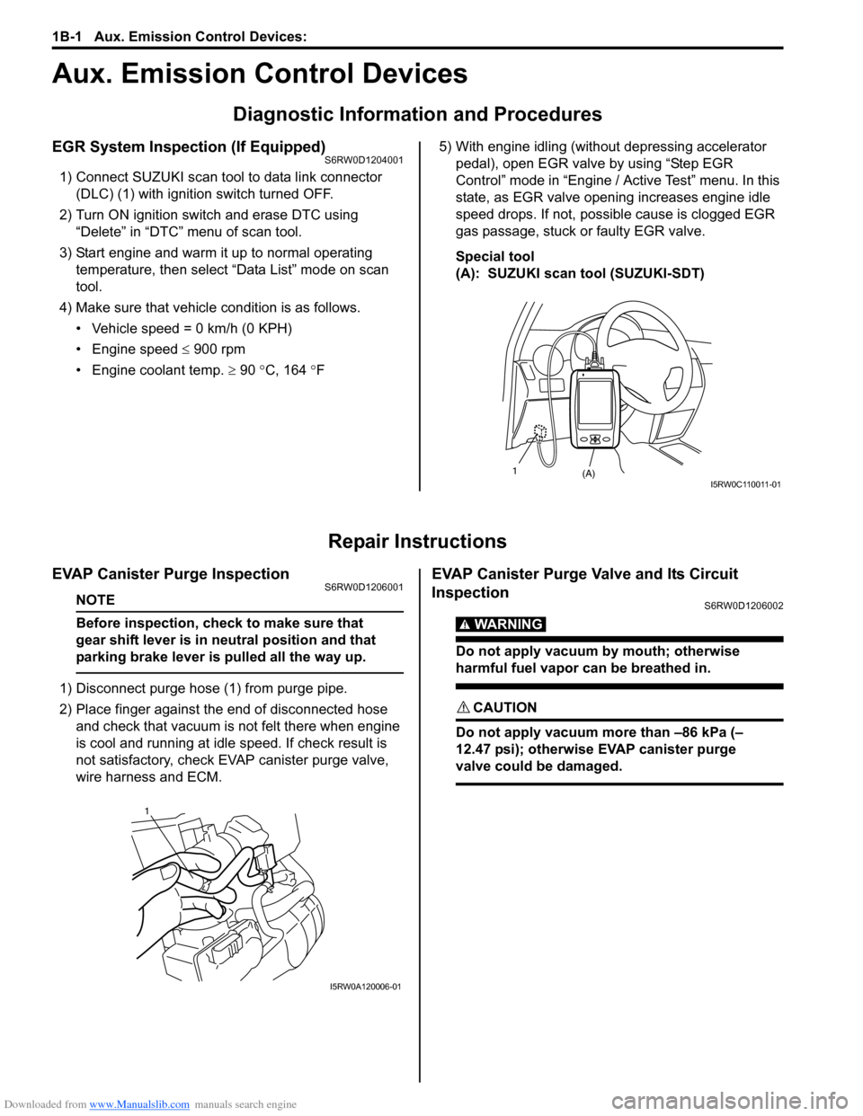
EGR System Inspection (If Equipped)S6RW0D1204001
1) Connect SUZUKI scan tool to data link connector
(DLC) (1) with ignition switch turned OFF.
2) Turn ON ignition switch and erase DTC using
“Delete” in “DTC” menu of scan tool.
3) Start engine and warm it up to normal operating
temperature, then select “Data List” mode on scan
tool.
4) Make sure that vehicle condition is as follows.
• Vehicle speed = 0 km/h (0 KPH)
• Engine speed ≤ 900 rpm
• Engine coolant temp. ≥ 90 °C, 164 °F5) With engine idling (without depressing accelerator
pedal), open EGR valve by using “Step EGR
Control” mode in “Engine / Active Test” menu. In this
state, as EGR valve opening increases engine idle
speed drops. If not, possible cause is clogged EGR
gas passage, stuck or faulty EGR valve.
Special tool
(A): SUZUKI scan tool (SUZUKI-SDT)
Repair Instructions
EVAP Canister Purge InspectionS6RW0D1206001
NOTE
Before inspection, check to make sure that
gear shift lever is in neutral position and that
parking brake lever is pulled all the way up.
1) Disconnect purge hose (1) from purge pipe.
2) Place finger against the end of disconnected hose
and check that vacuum is not felt there when engine
is cool and running at idle speed. If check result is
not satisfactory, check EVAP canister purge valve,
wire harness and ECM.
EVAP Canister Purge Valve and Its Circuit
Inspection
S6RW0D1206002
WARNING!
Do not apply vacuum by mouth; otherwise
harmful fuel vapor can be breathed in.
CAUTION!
Do not apply vacuum more than –86 kPa (–
12.47 psi); otherwise EVAP canister purge
valve could be damaged.
(A) 1I5RW0C110011-01
1
I5RW0A120006-01