fuse box location SUZUKI SX4 2006 1.G Service Workshop Manual
[x] Cancel search | Manufacturer: SUZUKI, Model Year: 2006, Model line: SX4, Model: SUZUKI SX4 2006 1.GPages: 1556, PDF Size: 37.31 MB
Page 385 of 1556

Downloaded from www.Manualslib.com manuals search engine Fuel System: 1G-8
6) Start engine and run it until engine stops for lack of
fuel. Repeat cranking engine 2 – 3 times for about 3
seconds each time in order to dissipate fuel pressure
in lines. Fuel connections are now safe for servicing.
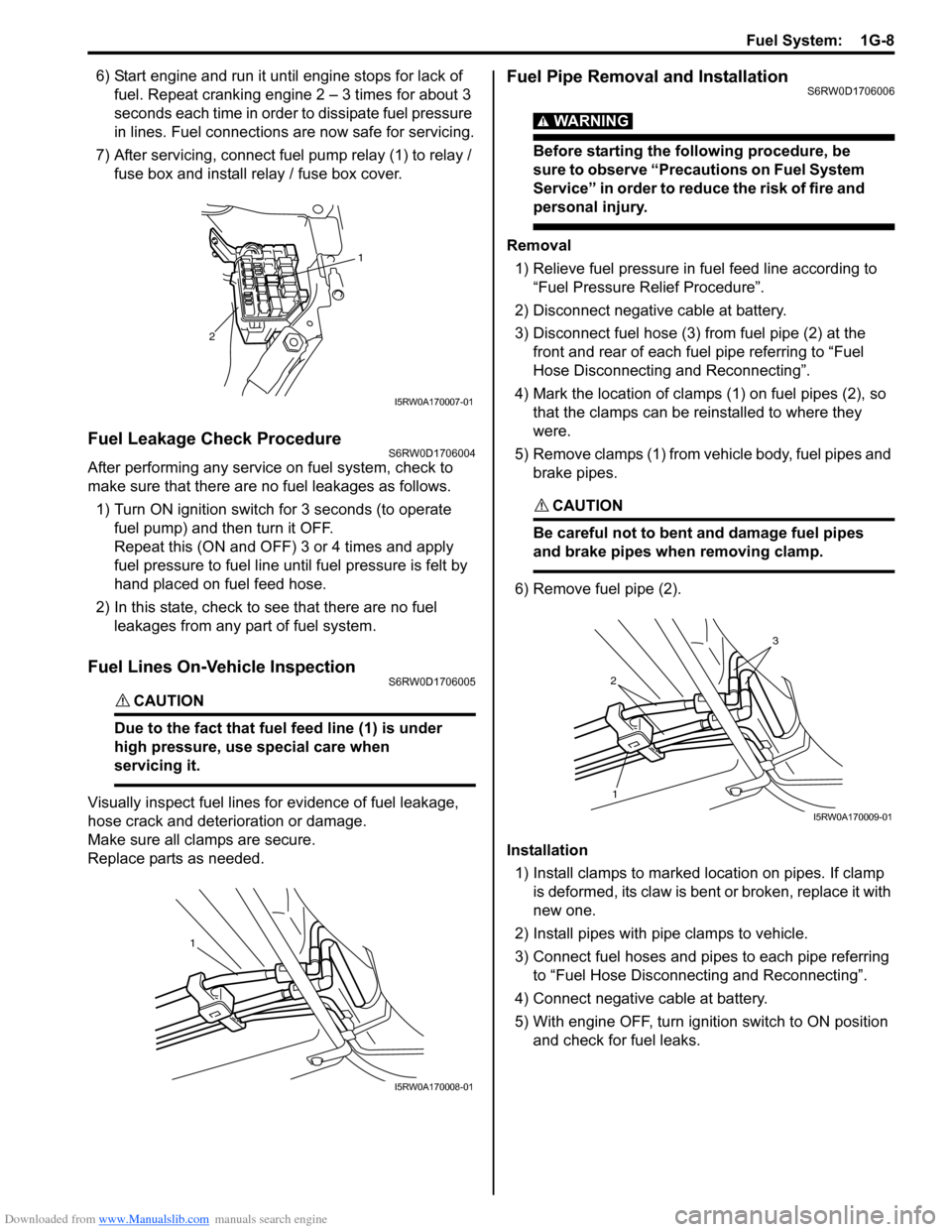
7) After servicing, connect fuel pump relay (1) to relay /
fuse box and install relay / fuse box cover.
Fuel Leakage Check ProcedureS6RW0D1706004
After performing any service on fuel system, check to
make sure that there are no fuel leakages as follows.
1) Turn ON ignition switch for 3 seconds (to operate
fuel pump) and then turn it OFF.
Repeat this (ON and OFF) 3 or 4 times and apply
fuel pressure to fuel line until fuel pressure is felt by
hand placed on fuel feed hose.
2) In this state, check to see that there are no fuel
leakages from any part of fuel system.
Fuel Lines On-Vehicle InspectionS6RW0D1706005
CAUTION!
Due to the fact that fuel feed line (1) is under
high pressure, use special care when
servicing it.
Visually inspect fuel lines for evidence of fuel leakage,
hose crack and deterioration or damage.
Make sure all clamps are secure.
Replace parts as needed.
Fuel Pipe Removal and InstallationS6RW0D1706006
WARNING!
Before starting the following procedure, be
sure to observe “Precautions on Fuel System
Service” in order to reduce the risk of fire and
personal injury.
Removal
1) Relieve fuel pressure in fuel feed line according to
“Fuel Pressure Relief Procedure”.
2) Disconnect negative cable at battery.
3) Disconnect fuel hose (3) from fuel pipe (2) at the
front and rear of each fuel pipe referring to “Fuel
Hose Disconnecting and Reconnecting”.
4) Mark the location of clamps (1) on fuel pipes (2), so
that the clamps can be reinstalled to where they
were.
5) Remove clamps (1) from vehicle body, fuel pipes and
brake pipes.
CAUTION!
Be careful not to bent and damage fuel pipes
and brake pipes when removing clamp.
6) Remove fuel pipe (2).
Installation
1) Install clamps to marked location on pipes. If clamp
is deformed, its claw is bent or broken, replace it with
new one.
2) Install pipes with pipe clamps to vehicle.
3) Connect fuel hoses and pipes to each pipe referring
to “Fuel Hose Disconnecting and Reconnecting”.
4) Connect negative cable at battery.
5) With engine OFF, turn ignition switch to ON position
and check for fuel leaks.
1
2
I5RW0A170007-01
1
I5RW0A170008-01
2
3
1
I5RW0A170009-01
Page 398 of 1556

Downloaded from www.Manualslib.com manuals search engine 1H-3 Ignition System:
Component Location
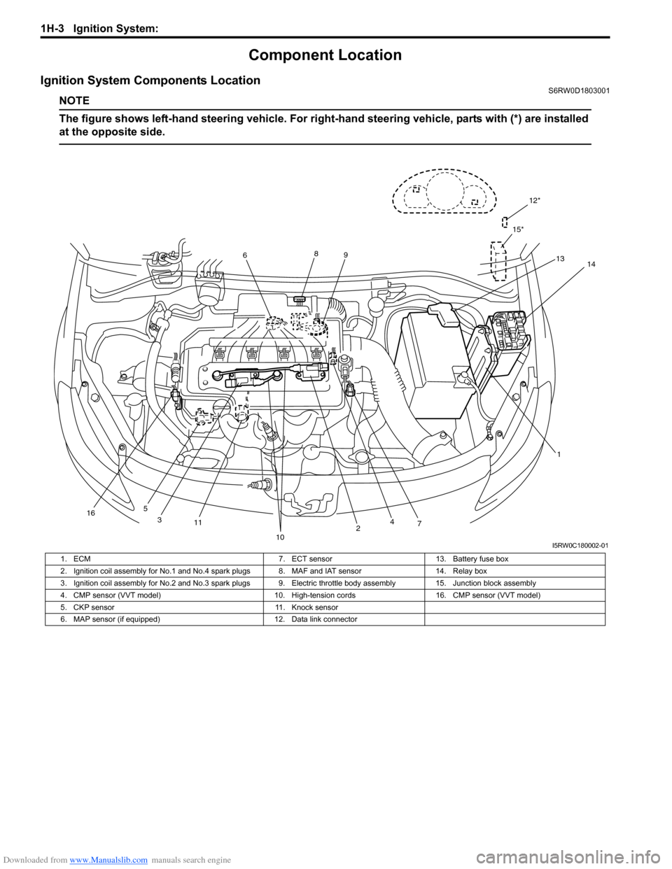
Ignition System Components LocationS6RW0D1803001
NOTE
The figure shows left-hand steering vehicle. For right-hand steering vehicle, parts with (*) are installed
at the opposite side.
12*
15*
13
1 689
11
10
74
5
14
2 3
16
I5RW0C180002-01
1. ECM 7. ECT sensor 13. Battery fuse box
2. Ignition coil assembly for No.1 and No.4 spark plugs 8. MAF and IAT sensor 14. Relay box
3. Ignition coil assembly for No.2 and No.3 spark plugs 9. Electric throttle body assembly 15. Junction block assembly
4. CMP sensor (VVT model) 10. High-tension cords 16. CMP sensor (VVT model)
5. CKP sensor 11. Knock sensor
6. MAP sensor (if equipped) 12. Data link connector
Page 930 of 1556

Downloaded from www.Manualslib.com manuals search engine 7A-2 Heater and Ventilation:
Schematic and Routing Diagram
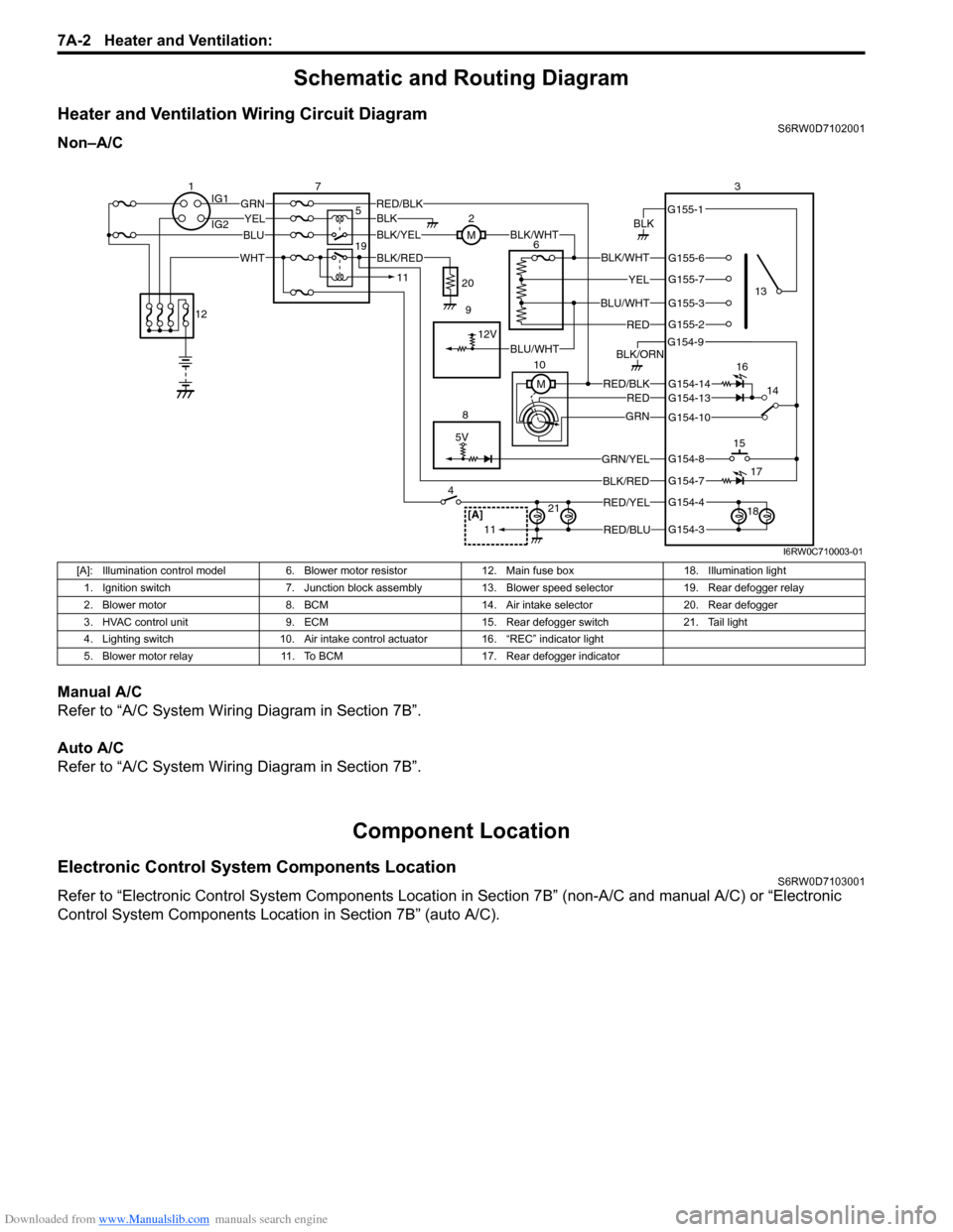
Heater and Ventilation Wiring Circuit DiagramS6RW0D7102001
Non–A/C
Manual A/C
Refer to “A/C System Wiring Diagram in Section 7B”.
Auto A/C
Refer to “A/C System Wiring Diagram in Section 7B”.
Component Location
Electronic Control System Components LocationS6RW0D7103001
Refer to “Electronic Control System Components Location in Section 7B” (non-A/C and manual A/C) or “Electronic
Control System Components Location in Section 7B” (auto A/C).
5V
BLK
RED/BLK3
5 72
G154-3
G154-4
G154-7
G154-8
G154-10
G154-13
G155-2
G155-3
G155-7
G155-6
G155-1
G154-9
G154-14
BLK/WHT
YEL
BLU/WHT
RED
RED/BLKRED
GRN
GRN/YEL
RED/YEL
RED/BLU
BLK/ORN
46
8
BLU
YELGRN
WHT
13
1514
[A]21
BLK/RED
12V
BLK/YELBLK/WHTM
BLK
1IG1
IG2
12
BLK/RED
M 10
11
11
BLU/WHT 19
16
17
18 9 20
I6RW0C710003-01
[A]: Illumination control model 6. Blower motor resistor 12. Main fuse box 18. Illumination light
1. Ignition switch 7. Junction block assembly 13. Blower speed selector 19. Rear defogger relay
2. Blower motor 8. BCM 14. Air intake selector 20. Rear defogger
3. HVAC control unit 9. ECM 15. Rear defogger switch 21. Tail light
4. Lighting switch 10. Air intake control actuator 16. “REC” indicator light
5. Blower motor relay 11. To BCM 17. Rear defogger indicator
Page 983 of 1556

Downloaded from www.Manualslib.com manuals search engine Air Conditioning System: Automatic Type 7B-43
Component Location
A/C System Major Components LocationS6RW0D7223001
Refer to “A/C System Major Components Location”.
[A]: Illumination control model 10. Air intake actuator 22. Compressor 34. “A/C” indicator light
[B]: Junction block with BCM 11. Air flow control actuator 23. HVAC control module 35. Rear defogger switch
[C]: Junction block without BCM 12. Temperature control actuator 24. BCM 36. Rear defogger indicator
1. Main fuse box 13. Inside air temperature sensor 25. A/C refrigerant pressure sensor 37. To other control module
2. Ignition switch 14. Outside air temperature sensor 26. Condenser cooling fan relay 38. Indicator light, switch,
selector
3. CAN junction connector 15. Evaporator temperature sensor 27. Information display 39. “FRE” indicator light
4. Rear defogger relay 16. Sunload sensor 28. Lighting switch 40. “REC” indicator light
5. Rear defogger 17. Junction block assembly 29. A/C switch 41. Temperature selector
6. Blower motor relay 18. ECM 30. Air intake selector 42. Blower speed selector
7. Blower motor 19. ECT sensor 31. To BCM 43. MODE (air flow) selector
8. Blower motor controller 20. Condenser cooling fan motor 32. ABS control module 44. Tail light
9. DLC 21. Compressor relay 33. Illumination light 45. Main relay