trim SUZUKI SX4 2006 1.G Service Manual PDF
[x] Cancel search | Manufacturer: SUZUKI, Model Year: 2006, Model line: SX4, Model: SUZUKI SX4 2006 1.GPages: 1556, PDF Size: 37.31 MB
Page 1420 of 1556
Downloaded from www.Manualslib.com manuals search engine 9F-9 Security and Locks:
Power Door Lock Actuator Inspection (If
Equipped)
S6RW0D9606006
1) Remove door trim from door panel.
For front door, refer to Step 1) to 3) of “Front Door
Glass Removal and Installation in Section 9E”.
For rear door, refer to Step 1) to 3) of “Rear Door
Glass Removal and Installation in Section 9E”.
For rear end door, refer to Step 1) of “Rear End Door
Assembly Removal and Installation in Section 9J”.
2) Disconnect power door lock actuator coupler.
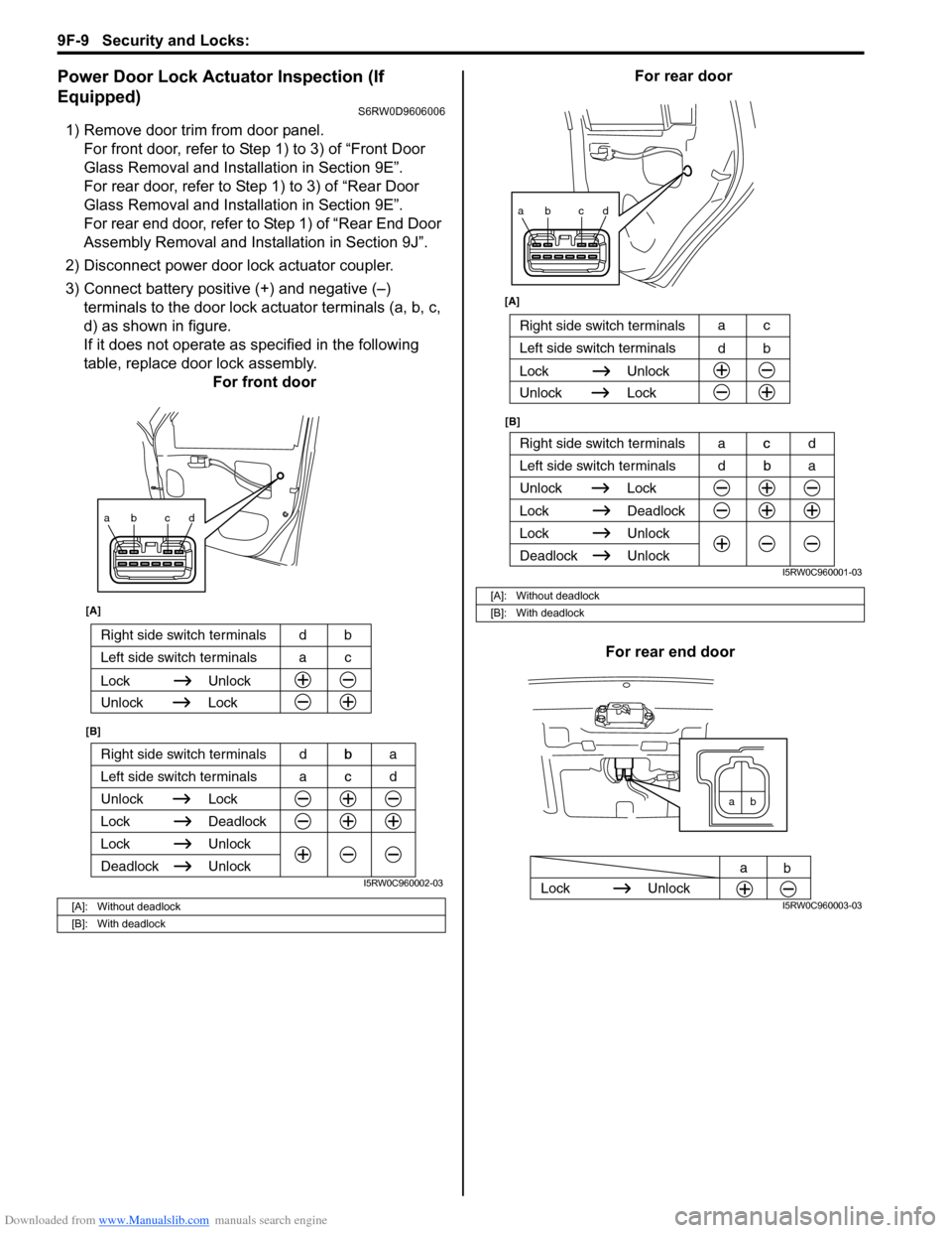
3) Connect battery positive (+) and negative (–)
terminals to the door lock actuator terminals (a, b, c,
d) as shown in figure.
If it does not operate as specified in the following
table, replace door lock assembly.
For front doorFor rear door
For rear end door
[A]: Without deadlock
[B]: With deadlock
ab cd
Right side switch terminals b
Unlock Lock
Lock Deadlock
Lock Unlock
Left side switch terminals c
Unlock
Deadlock
[A]
[B]
Right side switch terminals bd
Unlock Lock
Lock Unlock
Left side switch terminals ca
acd dba
I5RW0C960002-03
[A]: Without deadlock
[B]: With deadlock
ab cd
Right side switch terminals c
Unlock Lock
Lock Deadlock
Lock Unlock
Left side switch terminals b
Unlock
Deadlock
[B] [A]
Right side switch terminals
b d
Unlock Lock
Lock Unlock
Left side switch terminalsc a
dba acd
I5RW0C960001-03
ab
Lock Unlock
a
b
I5RW0C960003-03
Page 1421 of 1556

Downloaded from www.Manualslib.com manuals search engine Security and Locks: 9F-10
Rear Door Lock Assembly ComponentsS6RW0D9606007
Rear Door Lock Assembly Removal and
Installation
S6RW0D9606008
Removal
1) Remove rear door glass referring to “Rear Door
Glass Removal and Installation in Section 9E”.
2) Disconnect door lock motor lead wire (If equipped).
3) Remove door latch mounting screws (1) and remove
door latch assembly (2).
Installation
Reverse removal procedure to install rear door lock
assembly referring to the following instruction and “Front
Door Lock Assembly Removal and Installation”.• Tighten door latch screw to specified torque.
Tightening torque
Door latch screw (a): 5.0 N·m (0.5 kgf-m, 4.0 lb-ft)
• Install door trim referring to “Rear Door Glass
Removal and Installation in Section 9E”.
Rear Door Lock Assembly InspectionS6RW0D9606009
• Check that door opens and closes smoothly and
properly.
• Check that door stops in the secondary latched
position properly (preventing door from opening
freely) and that door closes completely in the fully
latched position.
• Adjust door latch striker position referring to “Front
Door Lock Assembly Removal and Installation”, if
necessary.
(a)
(b) 1
6
2
5
34
I5RW0A960006-01
1. Outside handle
: Apply lithium grease 99000-25011 to sliding part.4. Latch striker : 5.0 N⋅m
(0.5 kgf-m, 4.0 lb-ft)
2. Outside handle frame
: Apply lithium grease 99000-25011 to sliding part and spring.5. Inside handle bezel : 10 N⋅m
(1.0 kgf-m, 7.5 lb-ft)
3. Rear door latch assembly
: Apply lithium grease 99000-25011 to sliding part.6. Out side handle cap
1 2
I4RS0A960013-01
(a)
I4RS0A960014-01
Page 1423 of 1556

Downloaded from www.Manualslib.com manuals search engine Security and Locks: 9F-12
Rear End Door Lock Assembly Removal and
Installation
S6RW0D9606011
Removal
1) Remove door trim (1) from rear end door panel (2).
2) Disconnect door lock motor lead wire (if equipped).
3) Loosen door latch bolts (1) and remove door latch
assembly (2).
Installation
Reverse removal procedure to install rear end door lock
assembly noting the following instruction.
• Tighten rear end door latch bolt to specified torque.
Tightening torque
Rear end door latch bolt (a): 10 N·m (1.0 kgf-m,
7.5 lb-ft)• Adjust door latch striker so that its center aligns with
the center of groove in door latch base.
Tightening torque
Rear end door striker screw (a): 23 N·m (2.3 kgf-
m, 17.0 lb-ft)
Rear End Door Lock Assembly InspectionS6RW0D9606012
• Check that door opens and closes smoothly and
properly.
• Check that door stops in the secondary latched
position properly (preventing door from opening
freely) and that door closes completely in the fully
latched position.
• Adjust door latch striker position referring to “Front
Door Lock Assembly Removal and Installation”, if
necessary.
Rear End Door Opener Switch Inspection (If
Equipped)
S6RW0D9606013
1) Remove rear end door trim.
2) Disconnect rear end door switch coupler.
3) Check that there is continuity between terminals “a”
and “b” when rear end door opener switch (1) is
pushed.
4) Check that there is no continuity between terminals
when rear end door opener switch (1) is not pushed.
2
1
I5RW0A960008-02
1
2
I4RS0A960017-01
(a)
I4RS0A960018-01
(a)
I4RS0A960019-01
Page 1433 of 1556
Downloaded from www.Manualslib.com manuals search engine Interior Trim: 9H-1
Body, Cab and Accessories
Interior Trim
Repair Instructions
Floor Carpet Removal and InstallationS6RW0D9806001
Removal
1) Remove front seat and rear seat referring to “Front
Seat Removal and Installation in Section 9G” and
“Rear Seat Removal and Installation in Section 9G”.
2) Remove seat belt lower anchor bolts (front and rear).
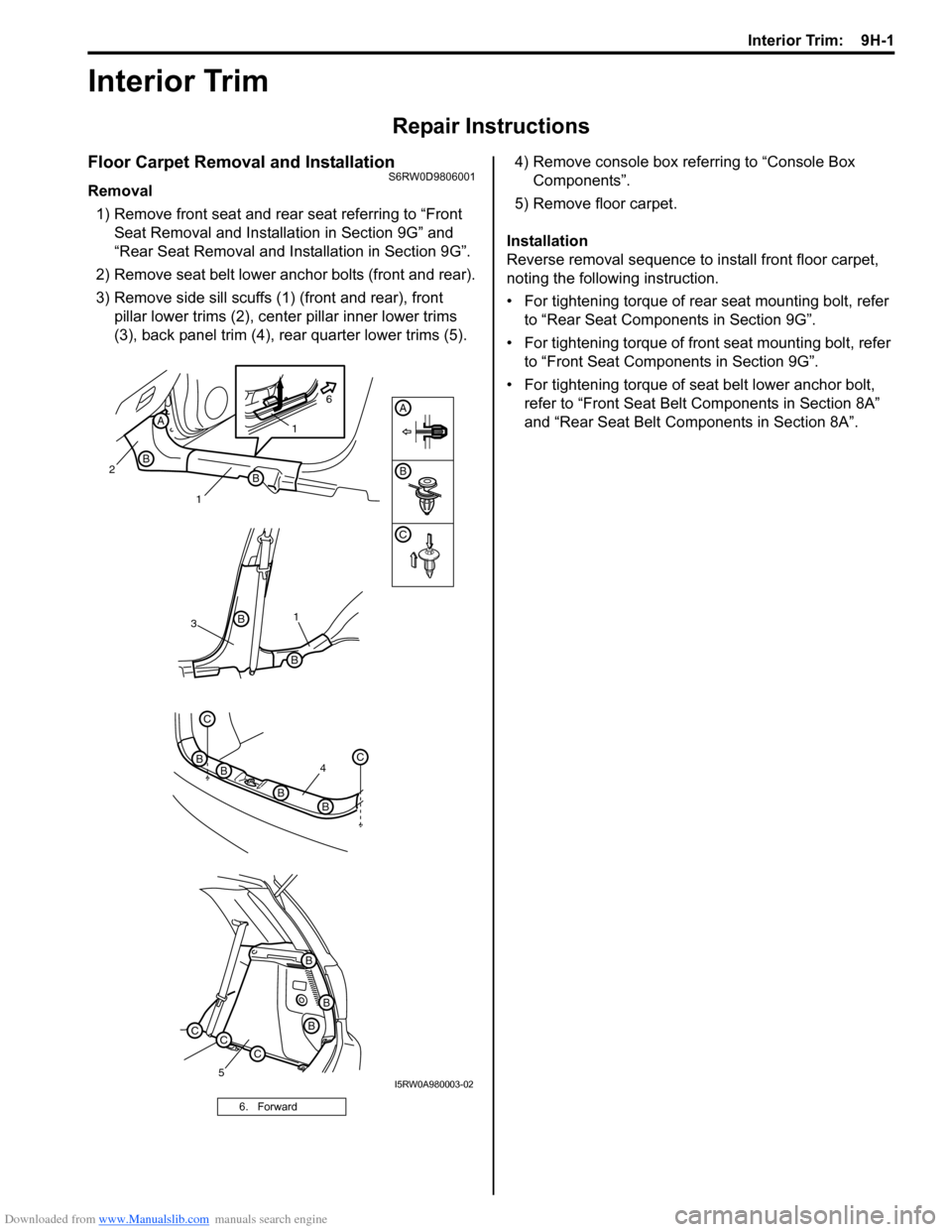
3) Remove side sill scuffs (1) (front and rear), front
pillar lower trims (2), center pillar inner lower trims
(3), back panel trim (4), rear quarter lower trims (5).4) Remove console box referring to “Console Box
Components”.
5) Remove floor carpet.
Installation
Reverse removal sequence to install front floor carpet,
noting the following instruction.
• For tightening torque of rear seat mounting bolt, refer
to “Rear Seat Components in Section 9G”.
• For tightening torque of front seat mounting bolt, refer
to “Front Seat Components in Section 9G”.
• For tightening torque of seat belt lower anchor bolt,
refer to “Front Seat Belt Components in Section 8A”
and “Rear Seat Belt Components in Section 8A”.
6. Forward
B
C
A
4
C
BC
BB
B
31
B
B
5
B
B
B
CCC
2
1B
B
A1
6
I5RW0A980003-02
Page 1434 of 1556
Downloaded from www.Manualslib.com manuals search engine 9H-2 Interior Trim:
Head Lining Removal and InstallationS6RW0D9806002
WARNING!
Refer to “Air Bag System Service Warning in
Section 00” before starting service work.
Removal
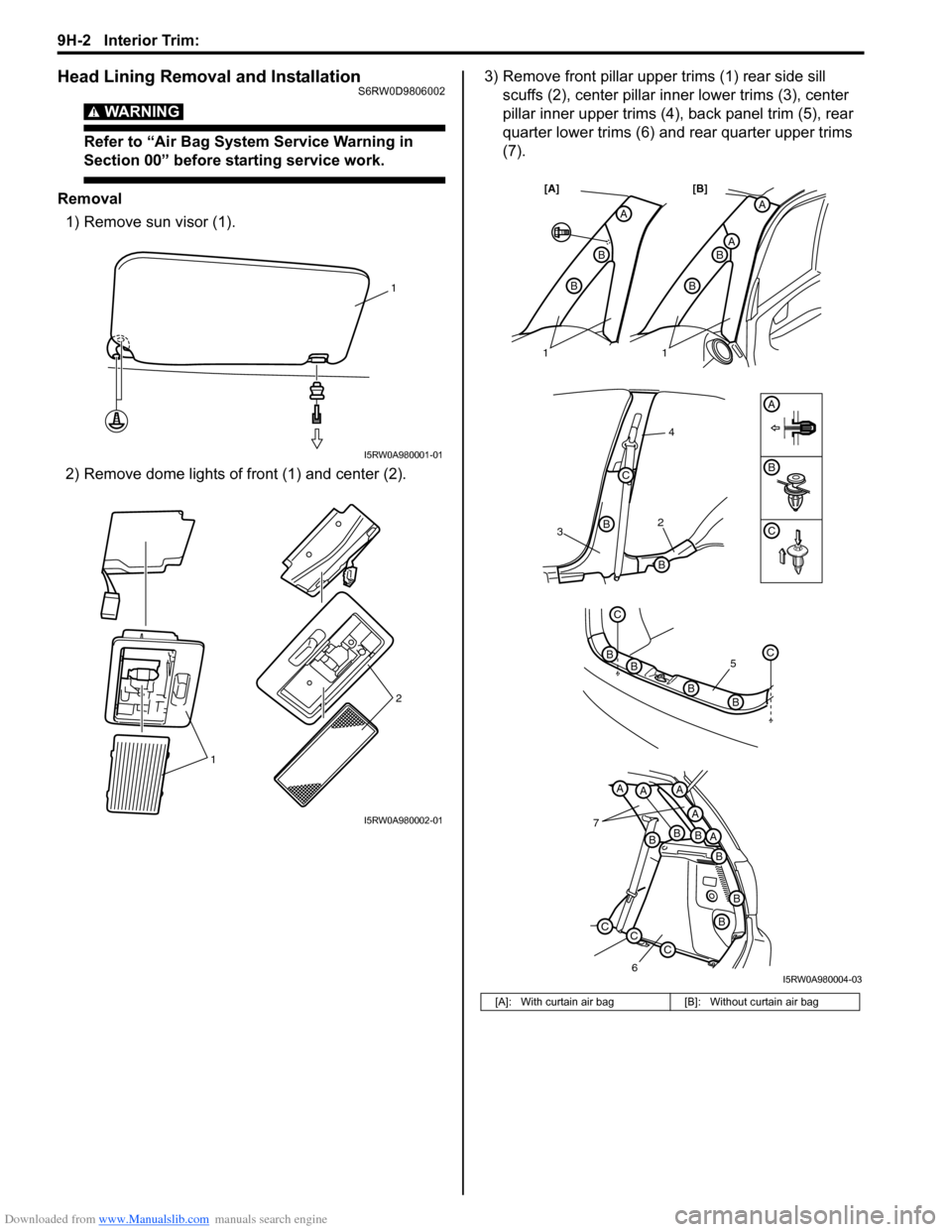
1) Remove sun visor (1).
2) Remove dome lights of front (1) and center (2).3) Remove front pillar upper trims (1) rear side sill
scuffs (2), center pillar inner lower trims (3), center
pillar inner upper trims (4), back panel trim (5), rear
quarter lower trims (6) and rear quarter upper trims
(7).
1
I5RW0A980001-01
12
I5RW0A980002-01
[A]: With curtain air bag [B]: Without curtain air bag
32
4
B
B
B
C
A
A
AB
B
A
B
B
[A] [B]
7
6
BBBA
A
AAA
B
B
B
CCC
5
C
BC
BB
B
11
C
I5RW0A980004-03
Page 1435 of 1556
Downloaded from www.Manualslib.com manuals search engine Interior Trim: 9H-3
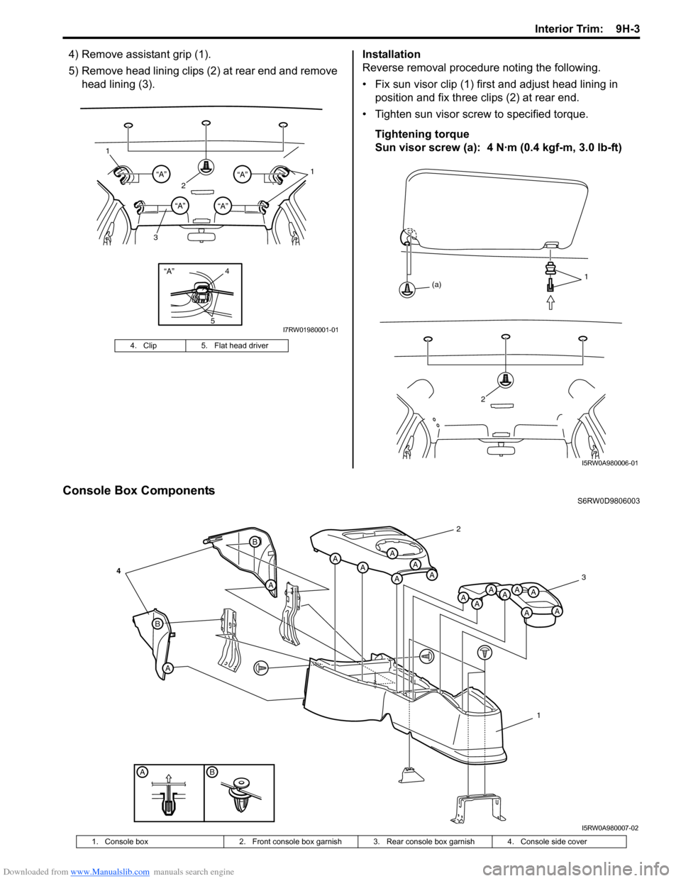
4) Remove assistant grip (1).
5) Remove head lining clips (2) at rear end and remove
head lining (3).Installation
Reverse removal procedure noting the following.
• Fix sun visor clip (1) first and adjust head lining in
position and fix three clips (2) at rear end.
• Tighten sun visor screw to specified torque.
Tightening torque
Sun visor screw (a): 4 N·m (0.4 kgf-m, 3.0 lb-ft)
Console Box ComponentsS6RW0D9806003 4. Clip 5. Flat head driver
“A”4
5
21 1
3“A”“A”
“A”“A”
I7RW01980001-01
2
1
(a)
I5RW0A980006-01
BA
B
A
A
B
AAA
AAA
A
AAAA
A
AA
2
3
1
4
I5RW0A980007-02
1. Console box 2. Front console box garnish 3. Rear console box garnish 4. Console side cover
Page 1436 of 1556
Downloaded from www.Manualslib.com manuals search engine 9H-4 Interior Trim:
Specifications
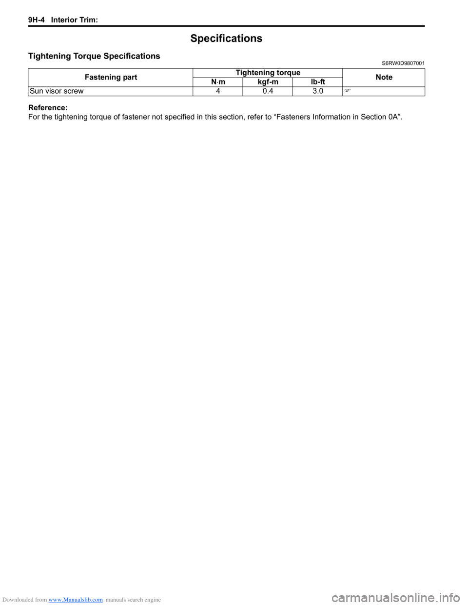
Tightening Torque SpecificationsS6RW0D9807001
Reference:
For the tightening torque of fastener not specified in this section, refer to “Fasteners Information in Section 0A”. Fastening partTightening torque
Note
N⋅mkgf-mlb-ft
Sun visor screw 4 0.4 3.0�)
Page 1442 of 1556
Downloaded from www.Manualslib.com manuals search engine 9J-6 Hood / Fenders / Doors:
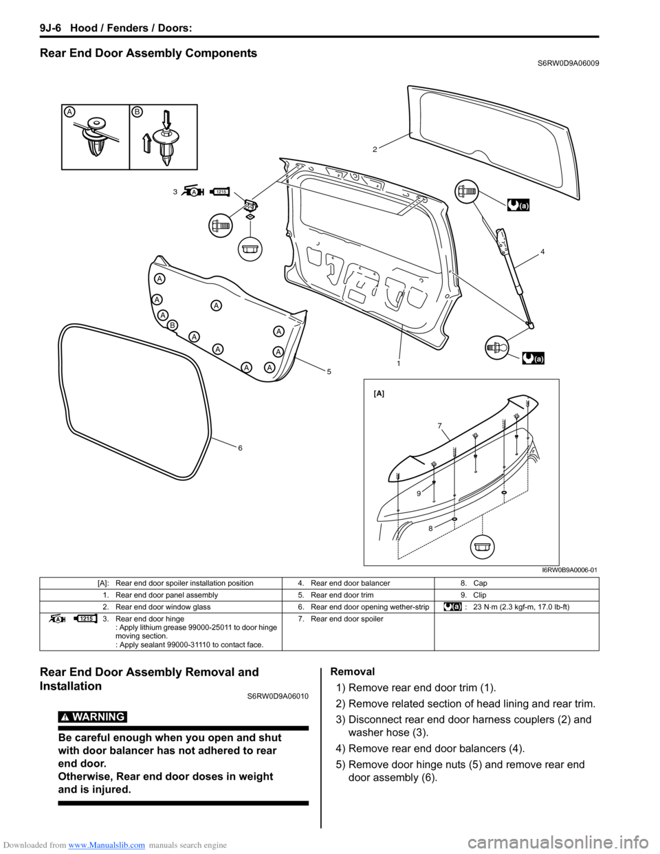
Rear End Door Assembly ComponentsS6RW0D9A06009
Rear End Door Assembly Removal and
Installation
S6RW0D9A06010
WARNING!
Be careful enough when you open and shut
with door balancer has not adhered to rear
end door.
Otherwise, Rear end door doses in weight
and is injured.
Removal
1) Remove rear end door trim (1).
2) Remove related section of head lining and rear trim.
3) Disconnect rear end door harness couplers (2) and
washer hose (3).
4) Remove rear end door balancers (4).
5) Remove door hinge nuts (5) and remove rear end
door assembly (6).
BA
A
B
A
A
A
A
A
AA
A
A
5
614 2
(a)
(a)
[A]
3
7
8
9
I6RW0B9A0006-01
[A]: Rear end door spoiler installation position 4. Rear end door balancer 8. Cap
1. Rear end door panel assembly 5. Rear end door trim 9. Clip
2. Rear end door window glass 6. Rear end door opening wether-strip : 23 N⋅m (2.3 kgf-m, 17.0 lb-ft)
3. Rear end door hinge
: Apply lithium grease 99000-25011 to door hinge
moving section.
: Apply sealant 99000-31110 to contact face.7. Rear end door spoiler
Page 1449 of 1556
Downloaded from www.Manualslib.com manuals search engine Body Structure: 9K-5
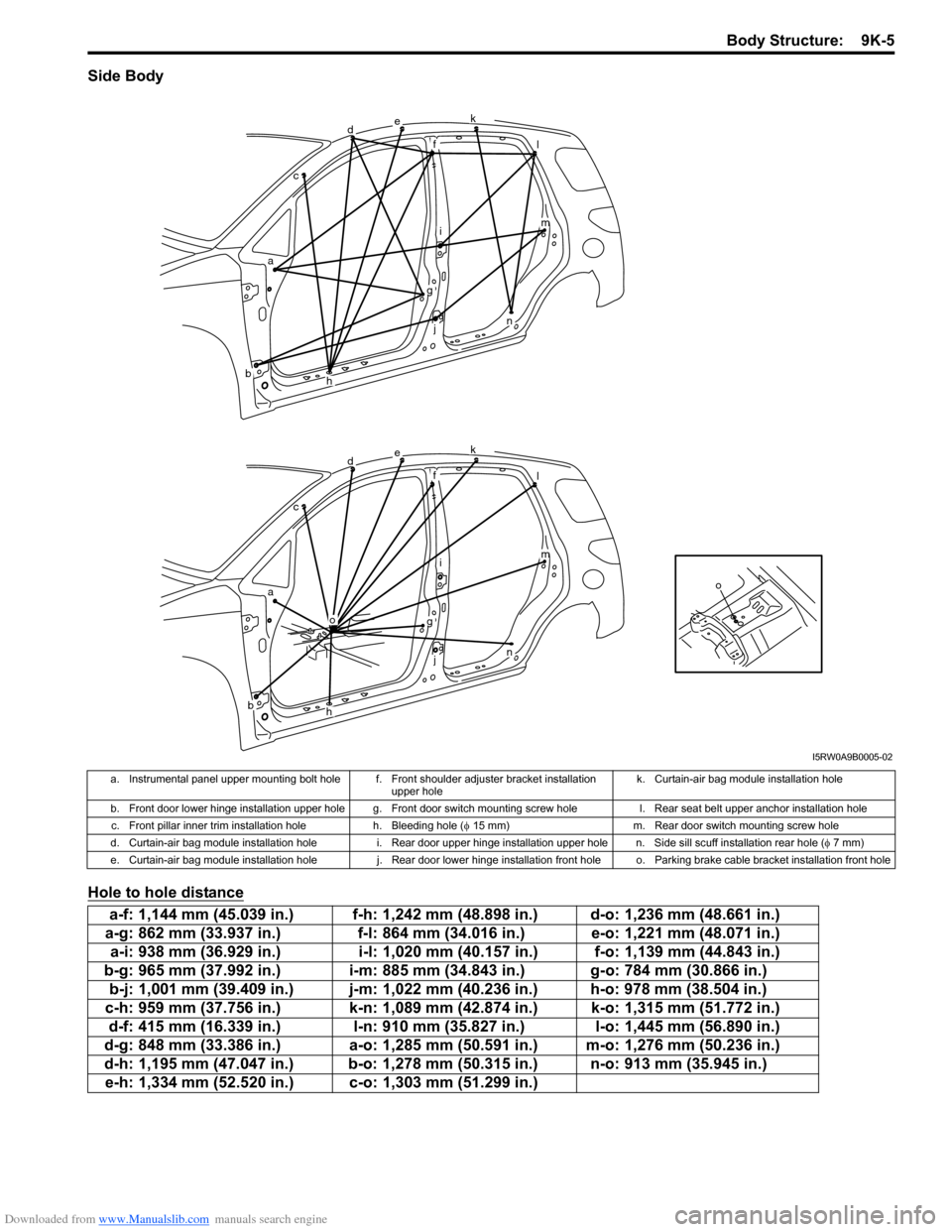
Side Body
Hole to hole distance
o
dek
fl
im
n
g
j
h
o
ac
b
dek
fl
im
n
g
j
h
ac
b
I5RW0A9B0005-02
a. Instrumental panel upper mounting bolt hole f. Front shoulder adjuster bracket installation
upper holek. Curtain-air bag module installation hole
b. Front door lower hinge installation upper hole g. Front door switch mounting screw hole l. Rear seat belt upper anchor installation hole
c. Front pillar inner trim installation hole h. Bleeding hole (φ 15 mm) m. Rear door switch mounting screw hole
d. Curtain-air bag module installation hole i. Rear door upper hinge installation upper hole n. Side sill scuff installation rear hole (φ 7 mm)
e. Curtain-air bag module installation hole j. Rear door lower hinge installation front hole o. Parking brake cable bracket installation front hole
a-f: 1,144 mm (45.039 in.) f-h: 1,242 mm (48.898 in.) d-o: 1,236 mm (48.661 in.)
a-g: 862 mm (33.937 in.) f-l: 864 mm (34.016 in.) e-o: 1,221 mm (48.071 in.)
a-i: 938 mm (36.929 in.) i-l: 1,020 mm (40.157 in.) f-o: 1,139 mm (44.843 in.)
b-g: 965 mm (37.992 in.) i-m: 885 mm (34.843 in.) g-o: 784 mm (30.866 in.)
b-j: 1,001 mm (39.409 in.) j-m: 1,022 mm (40.236 in.) h-o: 978 mm (38.504 in.)
c-h: 959 mm (37.756 in.) k-n: 1,089 mm (42.874 in.) k-o: 1,315 mm (51.772 in.)
d-f: 415 mm (16.339 in.) l-n: 910 mm (35.827 in.) l-o: 1,445 mm (56.890 in.)
d-g: 848 mm (33.386 in.) a-o: 1,285 mm (50.591 in.) m-o: 1,276 mm (50.236 in.)
d-h: 1,195 mm (47.047 in.) b-o: 1,278 mm (50.315 in.) n-o: 913 mm (35.945 in.)
e-h: 1,334 mm (52.520 in.) c-o: 1,303 mm (51.299 in.)
Page 1468 of 1556
Downloaded from www.Manualslib.com manuals search engine 9M-1 Exterior Trim:
Body, Cab and Accessories
Exterior Trim
Repair Instructions
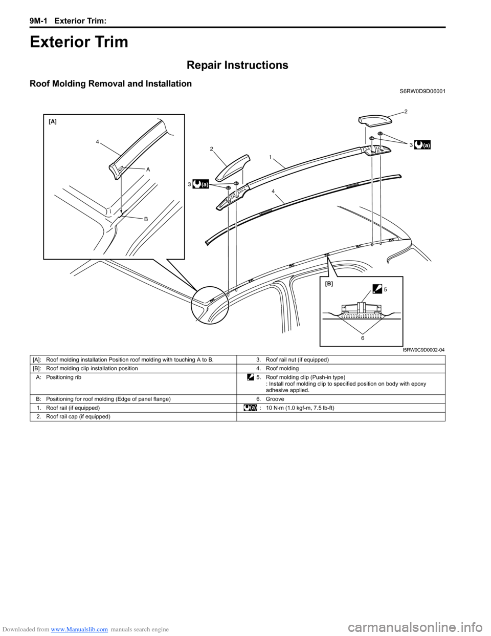
Roof Molding Removal and InstallationS6RW0D9D06001
2
312
3
44 [A]
A
B
[B]
5
6
(a)
(a)
I5RW0C9D0002-04
[A]: Roof molding installation Position roof molding with touching A to B. 3. Roof rail nut (if equipped)
[B]: Roof molding clip installation position 4. Roof molding
A: Positioning rib 5. Roof molding clip (Push-in type)
: Install roof molding clip to specified position on body with epoxy
adhesive applied.
B: Positioning for roof molding (Edge of panel flange) 6. Groove
1. Roof rail (if equipped) : 10 N⋅m (1.0 kgf-m, 7.5 lb-ft)
2. Roof rail cap (if equipped)