check engine SUZUKI SX4 2006 1.G Service Workshop Manual
[x] Cancel search | Manufacturer: SUZUKI, Model Year: 2006, Model line: SX4, Model: SUZUKI SX4 2006 1.GPages: 1556, PDF Size: 37.31 MB
Page 1543 of 1556
Downloaded from www.Manualslib.com manuals search engine Keyless Start System: 10E-21
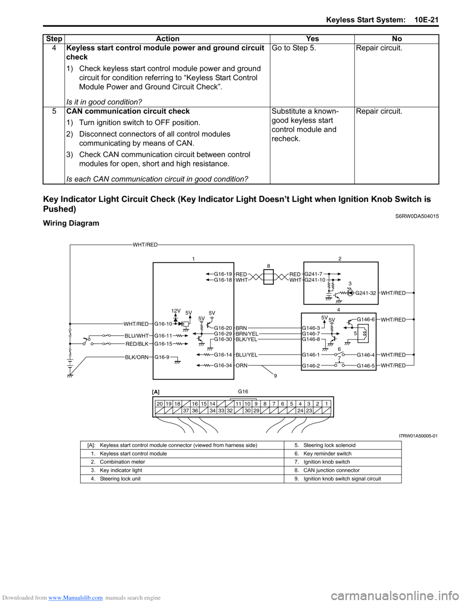
Key Indicator Light Circuit Check (Key Indicator Light Doesn’t Light when Ignition Knob Switch is
Pushed)
S6RW0DA504015
Wiring Diagram4Keyless start control module power and ground circuit
check
1) Check keyless start control module power and ground
circuit for condition referring to “Keyless Start Control
Module Power and Ground Circuit Check”.
Is it in good condition?Go to Step 5. Repair circuit.
5CAN communication circuit check
1) Turn ignition switch to OFF position.
2) Disconnect connectors of all control modules
communicating by means of CAN.
3) Check CAN communication circuit between control
modules for open, short and high resistance.
Is each CAN communication circuit in good condition?Substitute a known-
good keyless start
control module and
recheck.Repair circuit. Step Action Yes No
5V5V 5V5V5V 12V
1 2 3 4 5 6 7 8 9 10 11 14 15 16
36 34 33 32 30 29 24 23 37 18 19 20
12
4
5
7 6
[A]8
3
G16
9
WHT/RED
WHTREDG16-18G16-19WHTREDG241-10G241-7
WHT/REDG241-32
WHT/REDG146-6
G146-3G146-7G146-8
G146-1
G146-2G146-5
G146-4WHT/RED
WHT/RED
G16-20G16-29G16-30BLK/YELBRN/YELBRN
G16-14
G16-34
BLU/YEL
ORN
BLK/ORNG16-9
G16-15
G16-10
G16-11BLU/WHT
WHT/RED
RED/BLK
I7RW01A50005-01
[A]: Keyless start control module connector (viewed from harness side) 5. Steering lock solenoid
1. Keyless start control module 6. Key reminder switch
2. Combination meter 7. Ignition knob switch
3. Key indicator light 8. CAN junction connector
4. Steering lock unit 9. Ignition knob switch signal circuit
Page 1544 of 1556
Downloaded from www.Manualslib.com manuals search engine 10E-22 Keyless Start System:
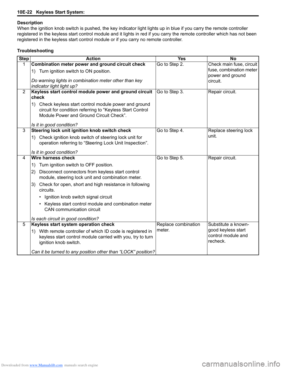
Description
When the ignition knob switch is pushed, the key indicator light lights up in blue if you carry the remote controller
registered in the keyless start control module and it lights in red if you carry the remote controller which has not been
registered in the keyless start control module or if you carry no remote controller.
Troubleshooting
Step Action Yes No
1Combination meter power and ground circuit check
1) Turn ignition switch to ON position.
Do warning lights in combination meter other than key
indicator light light up?Go to Step 2. Check main fuse, circuit
fuse, combination meter
power and ground
circuit.
2Keyless start control module power and ground circuit
check
1) Check keyless start control module power and ground
circuit for condition referring to “Keyless Start Control
Module Power and Ground Circuit Check”.
Is it in good condition?Go to Step 3. Repair circuit.
3Steering lock unit ignition knob switch check
1) Check ignition knob switch of steering lock unit for
operation referring to “Steering Lock Unit Inspection”.
Is it in good condition?Go to Step 4. Replace steering lock
unit.
4Wire harness check
1) Turn ignition switch to OFF position.
2) Disconnect connectors from keyless start control
module, steering lock unit and combination meter.
3) Check for open, short and high resistance in following
circuits.
• Ignition knob switch signal circuit
• Keyless start control module and combination meter
CAN communication circuit
Is each circuit in good condition?Go to Step 5. Repair circuit.
5Keyless start system operation check
1) With remote controller of which ID code is registered in
keyless start control module carried with you, try to turn
ignition knob switch.
Can it be turned to any position other than “LOCK” position?Replace combination
meter.Substitute a known-
good keyless start
control module and
recheck.
Page 1545 of 1556
Downloaded from www.Manualslib.com manuals search engine Keyless Start System: 10E-23
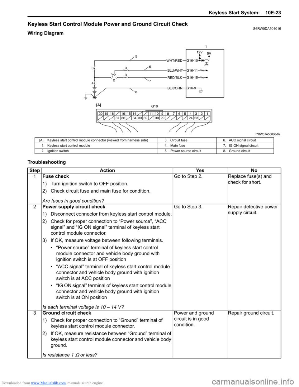
Keyless Start Control Module Power and Ground Circuit CheckS6RW0DA504016
Wiring Diagram
Troubleshooting
BLK/ORNG16-9
G16-15
G16-10
G16-11BLU/WHT
WHT/RED
RED/BLK
5V 12V
1 2 3 4 5 6 7 8 9 10 11 14 15 16
36 34 33 32 30 29 24 23 37 18 19 20
[A] 423
31
G16 5
86
7
3
I7RW01A50006-02
[A]: Keyless start control module connector (viewed from harness side) 3. Circuit fuse 6. ACC signal circuit
1. Keyless start control module 4. Main fuse 7. IG ON signal circuit
2. Ignition switch 5. Power source circuit 8. Ground circuit
Step Action Yes No
1Fuse check
1) Turn ignition switch to OFF position.
2) Check circuit fuse and main fuse for condition.
Are fuses in good condition?Go to Step 2. Replace fuse(s) and
check for short.
2Power supply circuit check
1) Disconnect connector from keyless start control module.
2) Check for proper connection to “Power source”, “ACC
signal” and “IG ON signal” terminal of keyless start
control module connector.
3) If OK, measure voltage between following terminals.
• “Power source” terminal of keyless start control
module connector and vehicle body ground with
ignition switch is at OFF position
• “ACC signal” terminal of keyless start control module
connector and vehicle body ground with ignition
switch is at ACC position
• “IG ON signal” terminal of keyless start control module
connector and vehicle body ground with ignition
switch is at ON position
Is each terminal voltage is 10 – 14 V?Go to Step 3. Repair defective power
supply circuit.
3Ground circuit check
1) Check for proper connection to “Ground” terminal of
keyless start control module connector.
2) If OK, measure resistance between “Ground” terminal of
keyless start control module connector and vehicle body
ground.
Is resistance 1
Ω or less?Power and ground
circuit is in good
condition.Repair ground circuit.
Page 1546 of 1556
Downloaded from www.Manualslib.com manuals search engine 10E-24 Keyless Start System:
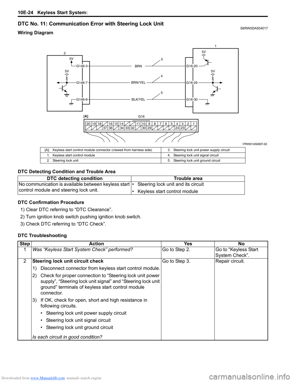
DTC No. 11: Communication Error with Steering Lock UnitS6RW0DA504017
Wiring Diagram
DTC Detecting Condition and Trouble Area
DTC Confirmation Procedure
1) Clear DTC referring to “DTC Clearance”.
2) Turn ignition knob switch pushing ignition knob switch.
3) Check DTC referring to “DTC Check”.
DTC Troubleshooting
5V
G16-20
G16-29
G16-30
G146-3
G146-7
G146-8
1 2 3 4 5 6 7 8 9 10 11 14 15 16
36 34 33 32 30 29 24 23 37 18 19 20
5V
5V
BRN
BRN/YEL
BLK/YEL
5V
21
[A]
G16
3
4
5
I7RW01A50007-02
[A]: Keyless start control module connector (viewed from harness side) 3. Steering lock unit power supply circuit
1. Keyless start control module 4. Steering lock unit signal circuit
2. Steering lock unit 5. Steering lock unit ground circuit
DTC detecting condition Trouble area
No communication is available between keyless start
control module and steering lock unit.• Steering lock unit and its circuit
• Keyless start control module
Step Action Yes No
1Was “Keyless Start System Check” performed?Go to Step 2. Go to “Keyless Start
System Check”.
2Steering lock unit circuit check
1) Disconnect connector from keyless start control module.
2) Check for proper connection to “Steering lock unit power
supply”, “Steering lock unit signal” and “Steering lock unit
ground” terminals of keyless start control module
connector.
3) If OK, check for open, short and high resistance in
following circuits.
• Steering lock unit power supply circuit
• Steering lock unit signal circuit
• Steering lock unit ground circuit
Is each circuit in good condition?Go to Step 3. Repair circuit.
Page 1547 of 1556
Downloaded from www.Manualslib.com manuals search engine Keyless Start System: 10E-25
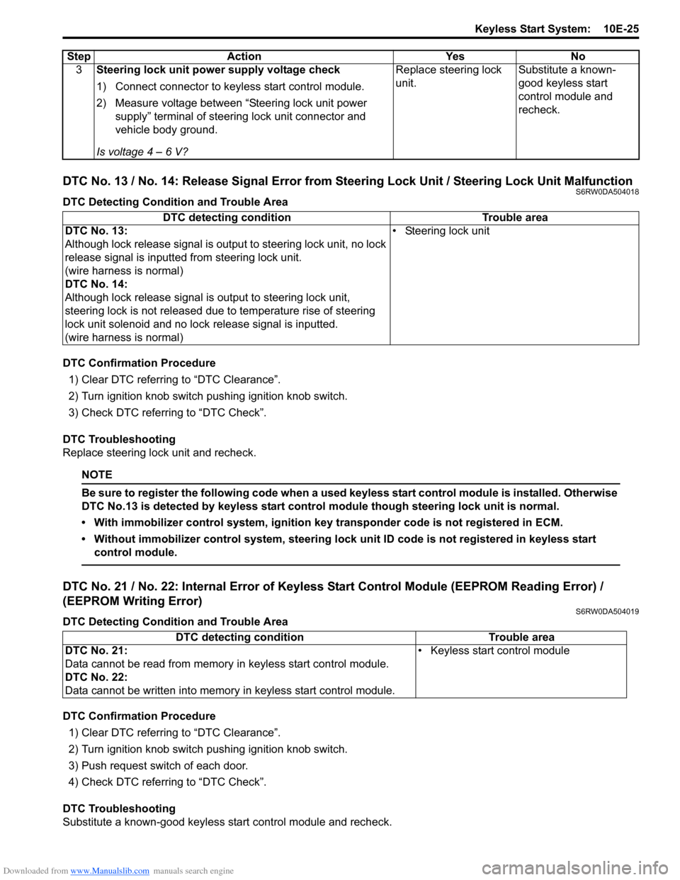
DTC No. 13 / No. 14: Release Signal Error from Steering Lock Unit / Steering Lock Unit MalfunctionS6RW0DA504018
DTC Detecting Condition and Trouble Area
DTC Confirmation Procedure
1) Clear DTC referring to “DTC Clearance”.
2) Turn ignition knob switch pushing ignition knob switch.
3) Check DTC referring to “DTC Check”.
DTC Troubleshooting
Replace steering lock unit and recheck.
NOTE
Be sure to register the following code when a used keyless start control module is installed. Otherwise
DTC No.13 is detected by keyless start control module though steering lock unit is normal.
• With immobilizer control system, ignition key transponder code is not registered in ECM.
• Without immobilizer control system, steering lock unit ID code is not registered in keyless start
control module.
DTC No. 21 / No. 22: Internal Error of Keyless Start Control Module (EEPROM Reading Error) /
(EEPROM Writing Error)
S6RW0DA504019
DTC Detecting Condition and Trouble Area
DTC Confirmation Procedure
1) Clear DTC referring to “DTC Clearance”.
2) Turn ignition knob switch pushing ignition knob switch.
3) Push request switch of each door.
4) Check DTC referring to “DTC Check”.
DTC Troubleshooting
Substitute a known-good keyless start control module and recheck.3Steering lock unit power supply voltage check
1) Connect connector to keyless start control module.
2) Measure voltage between “Steering lock unit power
supply” terminal of steering lock unit connector and
vehicle body ground.
Is voltage 4 – 6 V?Replace steering lock
unit.Substitute a known-
good keyless start
control module and
recheck. Step Action Yes No
DTC detecting condition Trouble area
DTC No. 13:
Although lock release signal is output to steering lock unit, no lock
release signal is inputted from steering lock unit.
(wire harness is normal)
DTC No. 14:
Although lock release signal is output to steering lock unit,
steering lock is not released due to temperature rise of steering
lock unit solenoid and no lock release signal is inputted.
(wire harness is normal)• Steering lock unit
DTC detecting condition Trouble area
DTC No. 21:
Data cannot be read from memory in keyless start control module.
DTC No. 22:
Data cannot be written into memory in keyless start control module.• Keyless start control module
Page 1548 of 1556
Downloaded from www.Manualslib.com manuals search engine 10E-26 Keyless Start System:
DTC No. 31: Lost Communication with BCMS6RW0DA504020
Refer to “Troubleshooting for CAN-DTC in Section 1A”.
DTC No. 33: Control Module Communication Bus OffS6RW0DA504021
Refer to “Troubleshooting for CAN-DTC in Section 1A”.
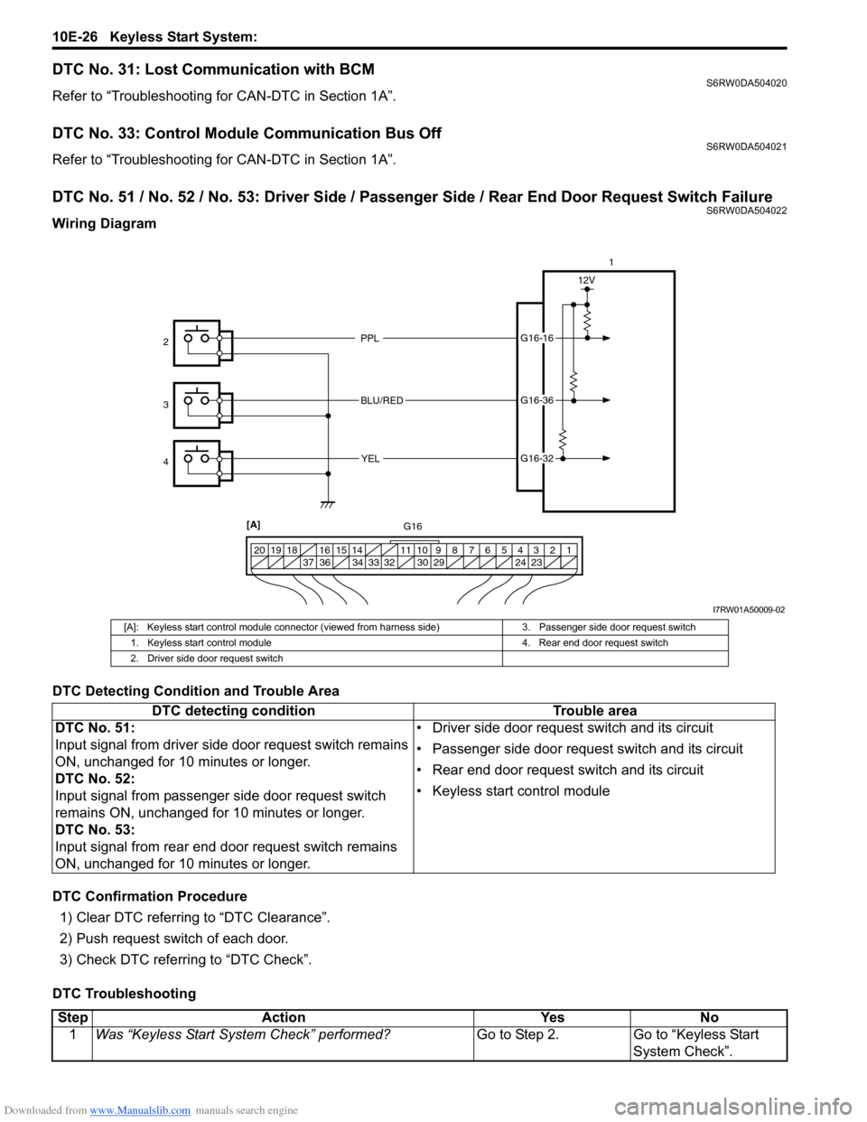
DTC No. 51 / No. 52 / No. 53: Driver Side / Passenger Side / Rear End Door Request Switch FailureS6RW0DA504022
Wiring Diagram
DTC Detecting Condition and Trouble Area
DTC Confirmation Procedure
1) Clear DTC referring to “DTC Clearance”.
2) Push request switch of each door.
3) Check DTC referring to “DTC Check”.
DTC Troubleshooting
PPL
BLU/RED
YELG16-16
G16-36
G16-32
12V
1 2 3 4 5 6 7 8 9 10 11 14 15 16
36 34 33 32 30 29 24 23 37 18 19 20
1
2
3
4
[A]
G16
I7RW01A50009-02
[A]: Keyless start control module connector (viewed from harness side) 3. Passenger side door request switch
1. Keyless start control module 4. Rear end door request switch
2. Driver side door request switch
DTC detecting condition Trouble area
DTC No. 51:
Input signal from driver side door request switch remains
ON, unchanged for 10 minutes or longer.
DTC No. 52:
Input signal from passenger side door request switch
remains ON, unchanged for 10 minutes or longer.
DTC No. 53:
Input signal from rear end door request switch remains
ON, unchanged for 10 minutes or longer.• Driver side door request switch and its circuit
• Passenger side door request switch and its circuit
• Rear end door request switch and its circuit
• Keyless start control module
Step Action Yes No
1Was “Keyless Start System Check” performed?Go to Step 2. Go to “Keyless Start
System Check”.
Page 1549 of 1556
Downloaded from www.Manualslib.com manuals search engine Keyless Start System: 10E-27
Repair Instructions
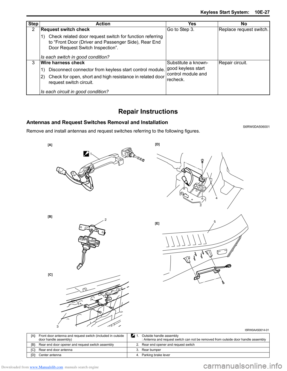
Antennas and Request Switches Removal and InstallationS6RW0DA506001
Remove and install antennas and request switches referring to the following figures.2Request switch check
1) Check related door request switch for function referring
to “Front Door (Driver and Passenger Side), Rear End
Door Request Switch Inspection”.
Is each switch in good condition?Go to Step 3. Replace request switch.
3Wire harness check
1) Disconnect connector from keyless start control module.
2) Check for open, short and high resistance in related door
request switch circuit.
Is each circuit in good condition?Substitute a known-
good keyless start
control module and
recheck.Repair circuit. Step Action Yes No
[A]
[B][D]
[C][E]
1
4
52
3I5RW0AA50014-01
[A]: Front door antenna and request switch (included in outside
door handle assembly)1. Outside handle assembly
: Antenna and request switch can not be removed from outside door handle assembly
[B]: Rear end door opener and request switch assembly 2. Rear end opener and request switch
[C]: Rear end door antenna 3. Rear bumper
[D]: Center antenna 4. Parking brake lever
Page 1550 of 1556
Downloaded from www.Manualslib.com manuals search engine 10E-28 Keyless Start System:
Front Door (Driver and Passenger Side), Rear
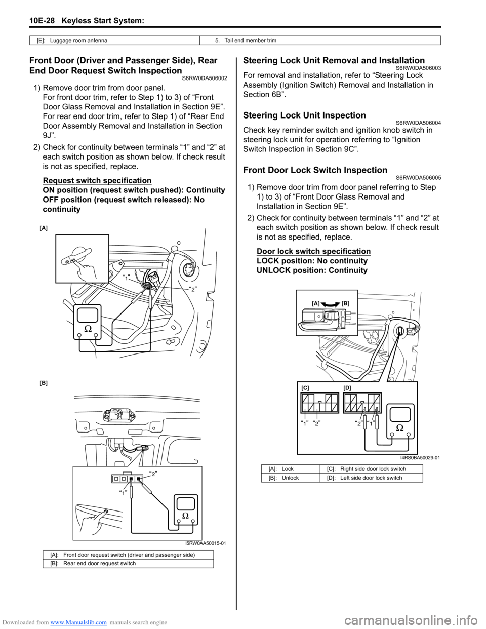
End Door Request Switch Inspection
S6RW0DA506002
1) Remove door trim from door panel.
For front door trim, refer to Step 1) to 3) of “Front
Door Glass Removal and Installation in Section 9E”.
For rear end door trim, refer to Step 1) of “Rear End
Door Assembly Removal and Installation in Section
9J”.
2) Check for continuity between terminals “1” and “2” at
each switch position as shown below. If check result
is not as specified, replace.
Request switch specification
ON position (request switch pushed): Continuity
OFF position (request switch released): No
continuity
Steering Lock Unit Removal and InstallationS6RW0DA506003
For removal and installation, refer to “Steering Lock
Assembly (Ignition Switch) Removal and Installation in
Section 6B”.
Steering Lock Unit InspectionS6RW0DA506004
Check key reminder switch and ignition knob switch in
steering lock unit for operation referring to “Ignition
Switch Inspection in Section 9C”.
Front Door Lock Switch InspectionS6RW0DA506005
1) Remove door trim from door panel referring to Step
1) to 3) of “Front Door Glass Removal and
Installation in Section 9E”.
2) Check for continuity between terminals “1” and “2” at
each switch position as shown below. If check result
is not as specified, replace.
Door lock switch specification
LOCK position: No continuity
UNLOCK position: Continuity
[E]: Luggage room antenna 5. Tail end member trim
[A]: Front door request switch (driver and passenger side)
[B]: Rear end door request switch
[A]
2
[B]
2
1
1
I5RW0AA50015-01
[A]: Lock [C]: Right side door lock switch
[B]: Unlock [D]: Left side door lock switch
[C] [D]
[A] [B]
1212
I4RS0BA50029-01
Page 1551 of 1556
Downloaded from www.Manualslib.com manuals search engine Keyless Start System: 10E-29
Keyless Start Control Module Removal and
Installation
S6RW0DA506006
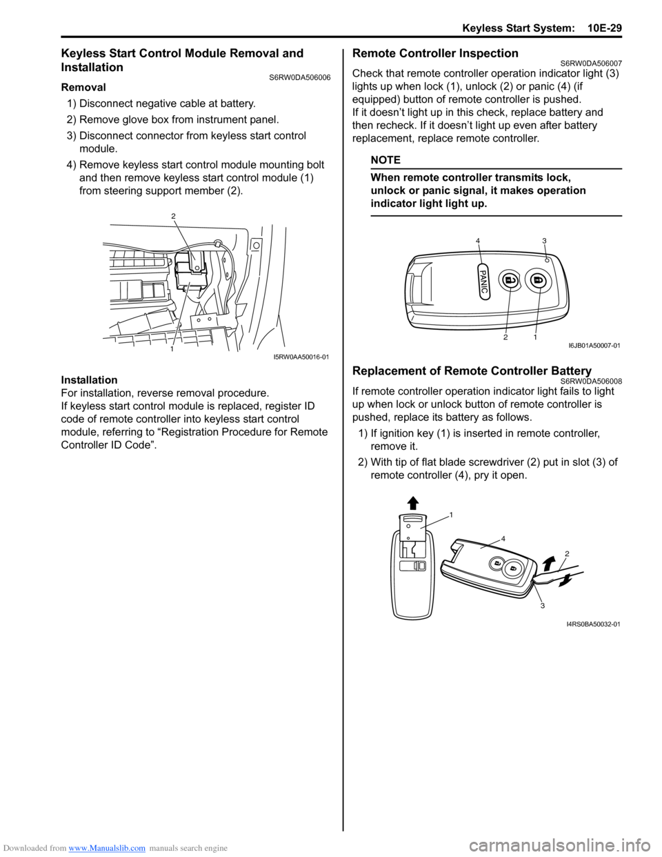
Removal
1) Disconnect negative cable at battery.
2) Remove glove box from instrument panel.
3) Disconnect connector from keyless start control
module.
4) Remove keyless start control module mounting bolt
and then remove keyless start control module (1)
from steering support member (2).
Installation
For installation, reverse removal procedure.
If keyless start control module is replaced, register ID
code of remote controller into keyless start control
module, referring to “Registration Procedure for Remote
Controller ID Code”.
Remote Controller InspectionS6RW0DA506007
Check that remote controller operation indicator light (3)
lights up when lock (1), unlock (2) or panic (4) (if
equipped) button of remote controller is pushed.
If it doesn’t light up in this check, replace battery and
then recheck. If it doesn’t light up even after battery
replacement, replace remote controller.
NOTE
When remote controller transmits lock,
unlock or panic signal, it makes operation
indicator light light up.
Replacement of Remote Controller BatteryS6RW0DA506008
If remote controller operation indicator light fails to light
up when lock or unlock button of remote controller is
pushed, replace its battery as follows.
1) If ignition key (1) is inserted in remote controller,
remove it.
2) With tip of flat blade screwdriver (2) put in slot (3) of
remote controller (4), pry it open.
1
2
I5RW0AA50016-01
43
21I6JB01A50007-01
1
4
2
3
I4RS0BA50032-01
Page 1553 of 1556
Downloaded from www.Manualslib.com manuals search engine Keyless Start System: 10E-31
If remote controller or keyless start control module is
replaced or additional remote controller is necessary,
register ID code(s) of remote controller.
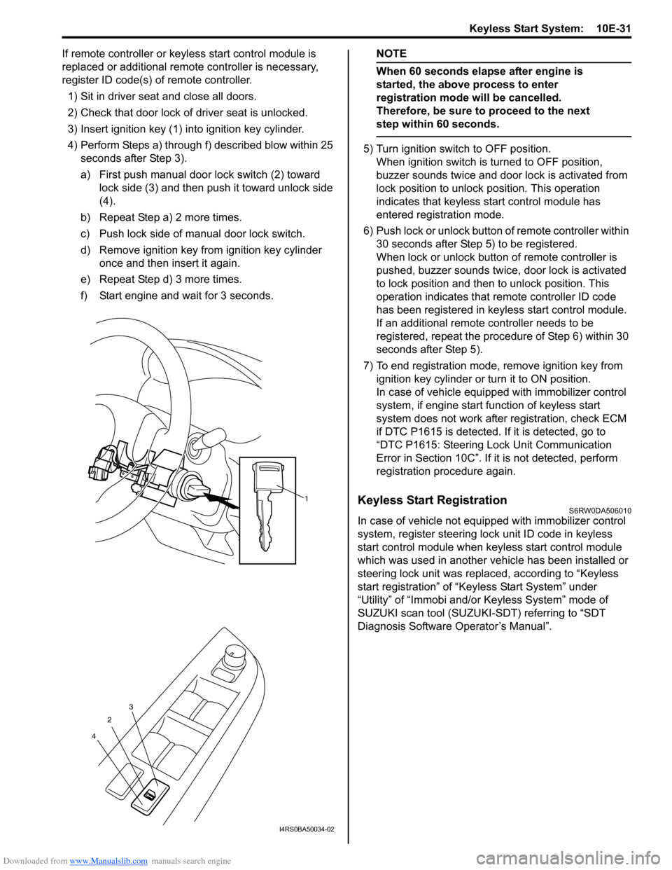
1) Sit in driver seat and close all doors.
2) Check that door lock of driver seat is unlocked.
3) Insert ignition key (1) into ignition key cylinder.
4) Perform Steps a) through f) described blow within 25
seconds after Step 3).
a) First push manual door lock switch (2) toward
lock side (3) and then push it toward unlock side
(4).
b) Repeat Step a) 2 more times.
c) Push lock side of manual door lock switch.
d) Remove ignition key from ignition key cylinder
once and then insert it again.
e) Repeat Step d) 3 more times.
f) Start engine and wait for 3 seconds.NOTE
When 60 seconds elapse after engine is
started, the above process to enter
registration mode will be cancelled.
Therefore, be sure to proceed to the next
step within 60 seconds.
5) Turn ignition switch to OFF position.
When ignition switch is turned to OFF position,
buzzer sounds twice and door lock is activated from
lock position to unlock position. This operation
indicates that keyless start control module has
entered registration mode.
6) Push lock or unlock button of remote controller within
30 seconds after Step 5) to be registered.
When lock or unlock button of remote controller is
pushed, buzzer sounds twice, door lock is activated
to lock position and then to unlock position. This
operation indicates that remote controller ID code
has been registered in keyless start control module.
If an additional remote controller needs to be
registered, repeat the procedure of Step 6) within 30
seconds after Step 5).
7) To end registration mode, remove ignition key from
ignition key cylinder or turn it to ON position.
In case of vehicle equipped with immobilizer control
system, if engine start function of keyless start
system does not work after registration, check ECM
if DTC P1615 is detected. If it is detected, go to
“DTC P1615: Steering Lock Unit Communication
Error in Section 10C”. If it is not detected, perform
registration procedure again.
Keyless Start RegistrationS6RW0DA506010
In case of vehicle not equipped with immobilizer control
system, register steering lock unit ID code in keyless
start control module when keyless start control module
which was used in another vehicle has been installed or
steering lock unit was replaced, according to “Keyless
start registration” of “Keyless Start System” under
“Utility” of “Immobi and/or Keyless System” mode of
SUZUKI scan tool (SUZUKI-SDT) referring to “SDT
Diagnosis Software Operator’s Manual”.
1
2
43
I4RS0BA50034-02