0b-6 SUZUKI SX4 2006 1.G Service Workshop Manual
[x] Cancel search | Manufacturer: SUZUKI, Model Year: 2006, Model line: SX4, Model: SUZUKI SX4 2006 1.GPages: 1556, PDF Size: 37.31 MB
Page 23 of 1556

Downloaded from www.Manualslib.com manuals search engine Table of Contents 0- i
0
Section 0
CONTENTS
General Information
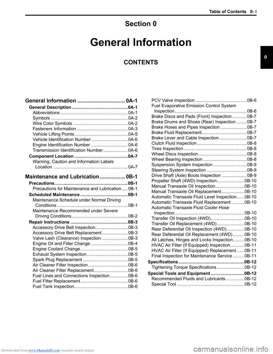
General Information ................................ 0A-1
General Description ............................................. 0A-1
Abbreviations ...................................................... 0A-1
Symbols .............................................................. 0A-2
Wire Color Symbols ............................................ 0A-2
Fasteners Information ......................................... 0A-3
Vehicle Lifting Points ........................................... 0A-5
Vehicle Identification Number ............................. 0A-6
Engine Identification Number .............................. 0A-6
Transmission Identification Number .................... 0A-6
Component Location ........................................... 0A-7
Warning, Caution and Information Labels
Location ............................................................ 0A-7
Maintenance and Lubrication ................. 0B-1
Precautions........................................................... 0B-1
Precautions for Maintenance and Lubrication ..... 0B-1
Scheduled Maintenance ...................................... 0B-1
Maintenance Schedule under Normal Driving
Conditions ......................................................... 0B-1
Maintenance Recommended under Severe
Driving Conditions ............................................. 0B-2
Repair Instructions .............................................. 0B-3
Accessory Drive Belt Inspection.......................... 0B-3
Accessory Drive Belt Replacement ..................... 0B-3
Valve Lash (Clearance) Inspection ..................... 0B-3
Engine Oil and Filter Change .............................. 0B-4
Engine Coolant Change ...................................... 0B-5
Exhaust System Inspection ................................. 0B-5
Spark Plug Replacement .................................... 0B-5
Air Cleaner Filter Inspection ................................ 0B-6
Air Cleaner Filter Replacement ........................... 0B-6
Fuel Lines and Connections Inspection .............. 0B-6
Fuel Filter Replacement ...................................... 0B-6
Fuel Tank Inspection ........................................... 0B-6PCV Valve Inspection ......................................... 0B-6
Fuel Evaporative Emission Control System
Inspection .......................................................... 0B-6
Brake Discs and Pads (Front) Inspection............ 0B-7
Brake Drums and Shoes (Rear) Inspection ........ 0B-7
Brake Hoses and Pipes Inspection ..................... 0B-7
Brake Fluid Replacement .................................... 0B-7
Brake Lever and Cable Inspection ...................... 0B-7
Clutch Fluid Inspection ........................................ 0B-8
Tires Inspection ................................................... 0B-8
Wheel Discs Inspection ....................................... 0B-8
Wheel Bearing Inspection ................................... 0B-8
Suspension System Inspection ........................... 0B-9
Steering System Inspection ................................ 0B-9
Drive Shaft (Axle) Boots Inspection .................... 0B-9
Propeller Shaft (4WD) Inspection...................... 0B-10
Manual Transaxle Oil Inspection ....................... 0B-10
Manual Transaxle Oil Replacement .................. 0B-10
Automatic Transaxle Fluid Level Inspection...... 0B-10
Automatic Transaxle Fluid Replacement .......... 0B-10
Automatic Transaxle Fluid Cooler Hose
Inspection ........................................................ 0B-10
Transfer Oil Inspection (4WD)........................... 0B-10
Transfer Oil Replacement (4WD) ...................... 0B-10
Rear Deferential Oil Inspection (4WD) .............. 0B-10
Rear Deferential Oil Replacement (4WD) ......... 0B-10
All Latches, Hinges and Locks Inspection......... 0B-10
HVAC Air Filter (If Equipped) Inspection ........... 0B-11
HVAC Air Filter (If Equipped) Replacement ...... 0B-11
Final Inspection for Maintenance Service ......... 0B-11
Specifications .....................................................0B-12
Tightening Torque Specifications ...................... 0B-12
Special Tools and Equipment ...........................0B-12
Recommended Fluids and Lubricants............... 0B-12
Special Tool ...................................................... 0B-12
Page 37 of 1556

Downloaded from www.Manualslib.com manuals search engine Maintenance and Lubrication: 0B-6
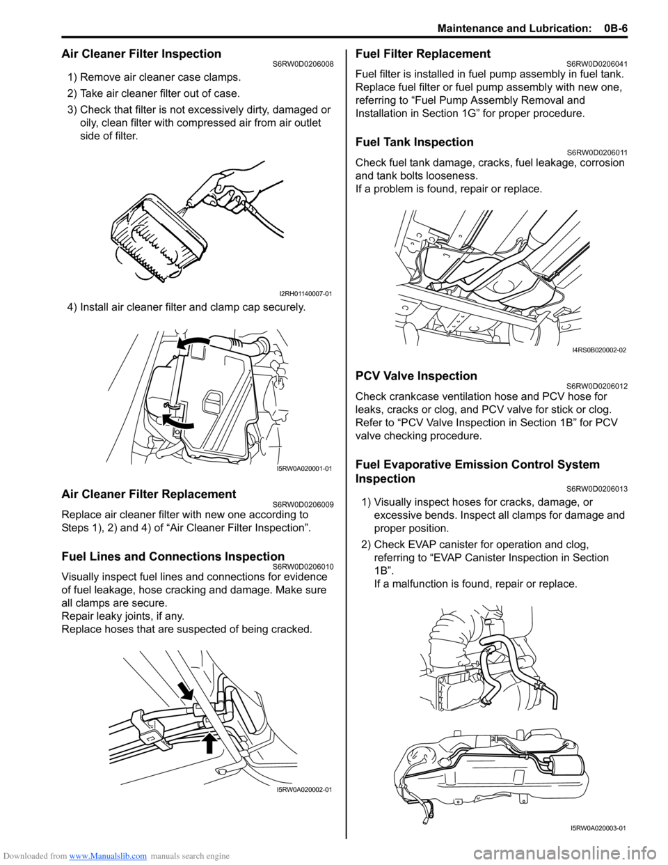
Air Cleaner Filter InspectionS6RW0D0206008
1) Remove air cleaner case clamps.
2) Take air cleaner filter out of case.
3) Check that filter is not excessively dirty, damaged or
oily, clean filter with compressed air from air outlet
side of filter.
4) Install air cleaner filter and clamp cap securely.
Air Cleaner Filter ReplacementS6RW0D0206009
Replace air cleaner filter with new one according to
Steps 1), 2) and 4) of “Air Cleaner Filter Inspection”.
Fuel Lines and Connections InspectionS6RW0D0206010
Visually inspect fuel lines and connections for evidence
of fuel leakage, hose cracking and damage. Make sure
all clamps are secure.
Repair leaky joints, if any.
Replace hoses that are suspected of being cracked.
Fuel Filter ReplacementS6RW0D0206041
Fuel filter is installed in fuel pump assembly in fuel tank.
Replace fuel filter or fuel pump assembly with new one,
referring to “Fuel Pump Assembly Removal and
Installation in Section 1G” for proper procedure.
Fuel Tank InspectionS6RW0D0206011
Check fuel tank damage, cracks, fuel leakage, corrosion
and tank bolts looseness.
If a problem is found, repair or replace.
PCV Valve InspectionS6RW0D0206012
Check crankcase ventilation hose and PCV hose for
leaks, cracks or clog, and PCV valve for stick or clog.
Refer to “PCV Valve Inspection in Section 1B” for PCV
valve checking procedure.
Fuel Evaporative Emission Control System
Inspection
S6RW0D0206013
1) Visually inspect hoses for cracks, damage, or
excessive bends. Inspect all clamps for damage and
proper position.
2) Check EVAP canister for operation and clog,
referring to “EVAP Canister Inspection in Section
1B”.
If a malfunction is found, repair or replace.
I2RH01140007-01
I5RW0A020001-01
I5RW0A020002-01
I4RS0B020002-02
I5RW0A020003-01
Page 1471 of 1556

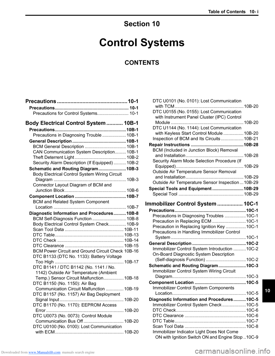
Downloaded from www.Manualslib.com manuals search engine Table of Contents 10- i
10
Section 10
CONTENTS
Control Systems
Precautions ............................................... 10-1
Precautions........................................................... 10-1
Precautions for Control Systems......................... 10-1
Body Electrical Control System ........... 10B-1
Precautions......................................................... 10B-1
Precautions in Diagnosing Trouble ................... 10B-1
General Description ........................................... 10B-1
BCM General Description ................................. 10B-1
CAN Communication System Description......... 10B-1
Theft Deterrent Light ......................................... 10B-2
Security Alarm Description (If Equipped) .......... 10B-2
Schematic and Routing Diagram ...................... 10B-3
Body Electrical Control System Wiring Circuit
Diagram .......................................................... 10B-3
Connector Layout Diagram of BCM and
Junction Block ................................................. 10B-6
Component Location ......................................... 10B-7
BCM and Related System Component
Location .......................................................... 10B-7
Diagnostic Information and Procedures .......... 10B-8
BCM Self-Diagnosis Function ........................... 10B-8
Body Electrical Control System Check.............. 10B-9
Scan Tool Data ............................................... 10B-11
DTC Table ....................................................... 10B-13
DTC Check ..................................................... 10B-14
DTC Clearance ............................................... 10B-15
BCM Power Circuit and Ground Circuit Check 10B-16
DTC B1133 (DTC No. 1133): Battery Voltage
Too High ....................................................... 10B-17
DTC B1141 / DTC B1142 (No. 1141 / No.
1142) Outside Air Temperature (Ambient
Temp.) Sensor Circuit Malfunction ................ 10B-18
DTC B1150 (No. 1150): Air Bag
Communication Circuit Malfunction .............. 10B-19
DTC B1157 (No. 1157) Air Bag Deployment
Signal Input ................................................... 10B-20
DTC B1170 (No. 1170): EEPROM Access
Error .............................................................. 10B-20
DTC U0073 (No. 0073): Control Module
Communication Bus Off ................................ 10B-20
DTC U0100 (No. 0100): Lost Communication
with ECM....................................................... 10B-20DTC U0101 (No. 0101): Lost Communication
with TCM ....................................................... 10B-20
DTC U0155 (No. 0155): Lost Communication
with Instrument Panel Cluster (IPC) Control
Module .......................................................... 10B-20
DTC U1144 (No. 1144): Lost Communication
with Keyless Start Control Module ................ 10B-20
Inspection of BCM and Its Circuits .................. 10B-21
Repair Instructions ..........................................10B-28
BCM (Included in Junction Block) Removal
and Installation .............................................. 10B-28
Security Alarm Mode Selection Procedure (If
Equipped) ...................................................... 10B-29
Outside Air Temperature Sensor Removal
and Installation .............................................. 10B-29
Outside Air Temperature Sensor Inspection ... 10B-29
Special Tools and Equipment .........................10B-29
Special Tool .................................................... 10B-29
Immobilizer Control System ................. 10C-1
Precautions.........................................................10C-1
Precautions in Diagnosing Troubles .................10C-1
Precaution in Replacing ECM ...........................10C-1
Precaution in Replacing Ignition Key ................10C-1
Precautions in Handling Immobilizer Control
System ............................................................10C-1
General Description ...........................................10C-2
Immobilizer Control System Introduction ..........10C-2
On-Board Diagnostic System Description
(Self-diagnosis Function)................................10C-2
Schematic and Routing Diagram ......................10C-3
Immobilizer Control System Wiring Circuit
Diagram...........................................................10C-3
Component Location .........................................10C-5
Immobilizer Control System Components
Location...........................................................10C-5
Diagnostic Information and Procedures ..........10C-5
Immobilizer Control System Check ...................10C-5
DTC Check........................................................10C-6
DTC Clearance .................................................10C-6
DTC Table .........................................................10C-7
Scan Tool Data .................................................10C-8
Immobilizer Indicator Light Does Not Come
ON with Ignition Switch ON and Engine Stop ..10C-9
Page 1479 of 1556

Downloaded from www.Manualslib.com manuals search engine Body Electrical Control System: 10B-6
Connector Layout Diagram of BCM and Junction BlockS6RW0DA202002
BCM and Junction Block Connectors (Viewed from Harness Side)
I6RW0CA20004-01
[A]: Junction block (viewed from BCM side) 2. Junction block 5. Rear wiper relay
[B]: Junction block (viewed from relay side) 3. Blower motor relay 6. Rear end door window defogger relay
1. BCM 4. Horn relay 7. Turn signal and hazard warning relay