800 SUZUKI SX4 2006 1.G Service Workshop Manual
[x] Cancel search | Manufacturer: SUZUKI, Model Year: 2006, Model line: SX4, Model: SUZUKI SX4 2006 1.GPages: 1556, PDF Size: 37.31 MB
Page 43 of 1556
Downloaded from www.Manualslib.com manuals search engine Maintenance and Lubrication: 0B-12
Steering
• Check to ensure that steering wheel is free from
instability, or abnormally heavy feeling.
• Check that the vehicle does not wander or pull to one
side.
Engine
• Check that engine responds readily at all speeds.
• Check that engine is free from abnormal noise and
abnormal vibration.
Body, Wheels and Power Transmitting System
Check that body, wheels and power transmitting system
are free from abnormal noise and abnormal vibration or
any other abnormal condition.Meters and Gauge
Check that speedometer, odometer, fuel meter,
temperature gauge, etc. are operating accurately.
Lights
Check that all lights operate properly.
Windshield Defroster
Periodically check that air comes out from defroster
outlet when operating heater or air conditioning.
Set mode control lever to defroster position and fan
switch lever to highest position for this check.
Specifications
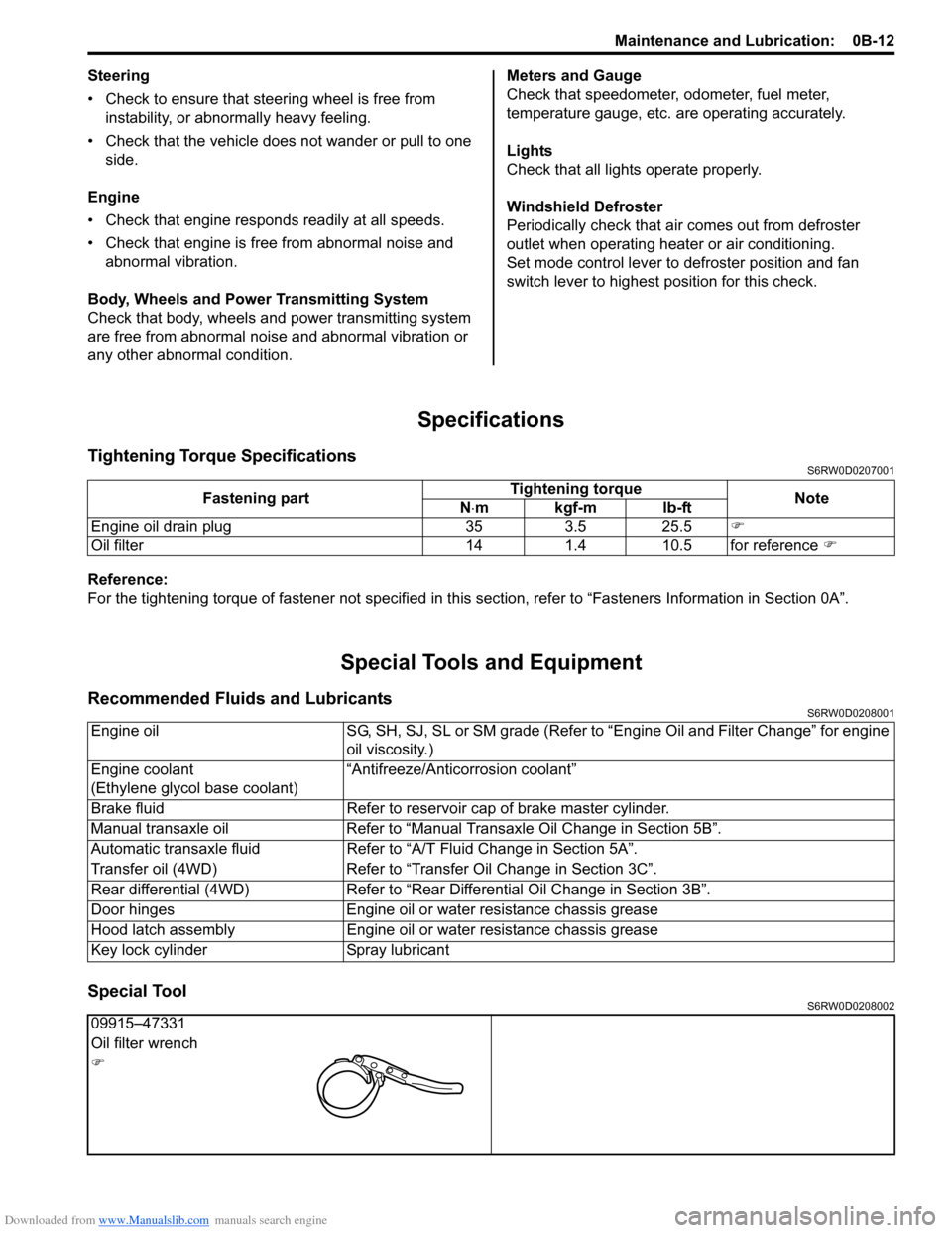
Tightening Torque SpecificationsS6RW0D0207001
Reference:
For the tightening torque of fastener not specified in this section, refer to “Fasteners Information in Section 0A”.
Special Tools and Equipment
Recommended Fluids and LubricantsS6RW0D0208001
Special ToolS6RW0D0208002
Fastening partTightening torque
Note
N⋅mkgf-mlb-ft
Engine oil drain plug 35 3.5 25.5)
Oil filter 14 1.4 10.5 for reference )
Engine oil SG, SH, SJ, SL or SM grade (Refer to “Engine Oil and Filter Change” for engine
oil viscosity.)
Engine coolant
(Ethylene glycol base coolant)“Antifreeze/Anticorrosion coolant”
Brake fluid Refer to reservoir cap of brake master cylinder.
Manual transaxle oil Refer to “Manual Transaxle Oil Change in Section 5B”.
Automatic transaxle fluid Refer to “A/T Fluid Change in Section 5A”.
Transfer oil (4WD) Refer to “Transfer Oil Change in Section 3C”.
Rear differential (4WD) Refer to “Rear Differential Oil Change in Section 3B”.
Door hinges Engine oil or water resistance chassis grease
Hood latch assembly Engine oil or water resistance chassis grease
Key lock cylinder Spray lubricant
09915–47331
Oil filter wrench
)
Page 230 of 1556
Downloaded from www.Manualslib.com manuals search engine 1A-180 Engine General Information and Diagnosis:
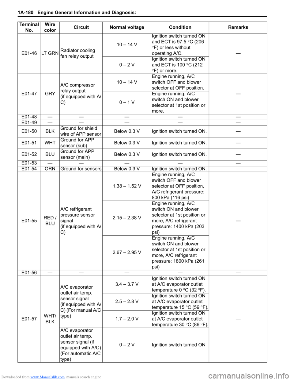
E01-46 LT GRNRadiator cooling
fan relay output10 – 14 VIgnition switch turned ON
and ECT is 97.5 °C (206
°F) or less without
operating A/C. —
0 – 2 VIgnition switch turned ON
and ECT is 100 °C (212
°F) or more.
E01-47 GRYA/C compressor
relay output
(if equipped with A/
C)10 – 14 VEngine running, A/C
switch OFF and blower
selector at OFF position.
—
0 – 1 VEngine running, A/C
switch ON and blower
selector at 1st position or
more.
E01-48 — — — — —
E01-49 — — — — —
E01-50 BLKGround for shield
wire of APP sensorBelow 0.3 V Ignition switch turned ON. —
E01-51 WHTGround for APP
sensor (sub)Below 0.3 V Ignition switch turned ON. —
E01-52 BLUGround for APP
sensor (main)Below 0.3 V Ignition switch turned ON. —
E01-53 — — — — —
E01-54 ORN Ground for sensors Below 0.3 V Ignition switch turned ON. —
E01-55RED /
BLUA/C refrigerant
pressure sensor
signal
(if equipped with A/
C)1.38 – 1.52 VEngine running, A/C
switch OFF and blower
selector at OFF position,
A/C refrigerant pressure:
800 kPa (116 psi)
— 2.15 – 2.38 VEngine running, A/C
switch ON and blower
selector at 1st position or
more, A/C refrigerant
pressure: 1400 kPa (203
psi)
2.67 – 2.95 VEngine running, A/C
switch ON and blower
selector at 1st position or
more, A/C refrigerant
pressure: 1800 kPa (261
psi)
E01-56 — — — — —
E01-57WHT/
BLKA/C evaporator
outlet air temp.
sensor signal
(if equipped with A/
C) (For manual A/C
type)3.4 – 3.7 VIgnition switch turned ON
at A/C evaporator outlet
temperature 0 °C (32 °F).
— 2.5 – 2.8 VIgnition switch turned ON
at A/C evaporator outlet
temperature 15 °C (59 °F).
1.7 – 2.0 VIgnition switch turned ON
at A/C evaporator outlet
temperature 30 °C (86 °F).
A/C evaporator
outlet air temp.
sensor signal (if
equipped with A/C)
(For automatic A/C
type)0 – 2 V Ignition switch turned ON Terminal
No.Wire
colorCircuit Normal voltage Condition Remarks
Page 263 of 1556

Downloaded from www.Manualslib.com manuals search engine Engine General Information and Diagnosis: 1A-213
1) Connect SUZUKI scan tool to DLC (1) with ignition
switch turned OFF.
Special tool
(A): SUZUKI scan tool (SUZUKI-SDT)2) Warm up engine to normal operating temperature.
3) Check engine idle speed and “IAC throttle opening”
by using “Data List” mode on scan tool to check “IAC
throttle opening”.
4) If check result is out of specification, inspect electric
throttle body assembly referring to “Electric Throttle
Body Assembly On-Vehicle Inspection in Section
1C”.
Engine idle speed
A/C OFF: 700 ± 50 rpm (IAC duty: 5 – 25%)
A/C ON: 750 ± 50 rpm
5) Check that specified engine idle speed is obtained
with A/C turned ON if vehicle is equipped with A/C.
If not, check A/C system referring to “A/C System
Circuits Check”.
Special Tools and Equipment
Special ToolS6RW0D1108001
(A) 1I5RW0C110011-01
09912–58432 09912–58442
Fuel pressure gauge hose Fuel pressure gauge
This tool is included in fuel
pressure gauge set (09912-
58413). )This tool is included in fuel
pressure gauge set (09912-
58413). )
09912–58490 09933–06320
3-way joint & hose ECM check harness (120P)
)) / )
SUZUKI scan tool (SUZUKI-
SDT)
—
This kit includes following
items. 1. SUZUKI-SDT 2.
DLC3 cable 3. USB cable 4.
AC/DC power supply 5.
Voltage meter probe 6.
Storage case ) / )
1
2
34
56
Page 268 of 1556
Downloaded from www.Manualslib.com manuals search engine 1B-5 Aux. Emission Control Devices:
PCV Hose InspectionS6RW0D1206009
NOTE
Be sure to check that there is no obstruction
in PCV valve or its hoses before checking
IAC throttle valve opening, for obstructed
PCV valve or hose hampers its accurate
adjustment.
Check hoses for connection, leakage, clog and
deterioration.
Replace as necessary.
PCV Valve InspectionS6RW0D1206010
NOTE
Be sure to check that there is no obstruction
in PCV valve or its hoses before checking
IAC throttle valve opening, for obstructed
PCV valve or hose hampers its accurate
adjustment.
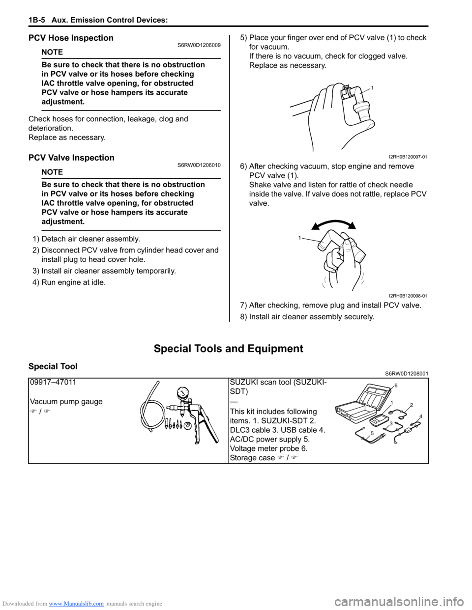
1) Detach air cleaner assembly.
2) Disconnect PCV valve from cylinder head cover and
install plug to head cover hole.
3) Install air cleaner assembly temporarily.
4) Run engine at idle.5) Place your finger over end of PCV valve (1) to check
for vacuum.
If there is no vacuum, check for clogged valve.
Replace as necessary.
6) After checking vacuum, stop engine and remove
PCV valve (1).
Shake valve and listen for rattle of check needle
inside the valve. If valve does not rattle, replace PCV
valve.
7) After checking, remove plug and install PCV valve.
8) Install air cleaner assembly securely.
Special Tools and Equipment
Special ToolS6RW0D1208001
I2RH0B120007-01
I2RH0B120008-01
09917–47011 SUZUKI scan tool (SUZUKI-
SDT)
Vacuum pump gauge —
) / )This kit includes following
items. 1. SUZUKI-SDT 2.
DLC3 cable 3. USB cable 4.
AC/DC power supply 5.
Voltage meter probe 6.
Storage case ) / )
1
2
34
56
Page 270 of 1556
Downloaded from www.Manualslib.com manuals search engine 1C-2 Engine Electrical Devices:
Manifold Absolute Pressure (MAP) Sensor
Inspection (If Equipped)
S6RW0D1306002
1) Remove air cleaner assembly.
2) Disconnect connector from MAP sensor.
3) Remove MAP sensor.
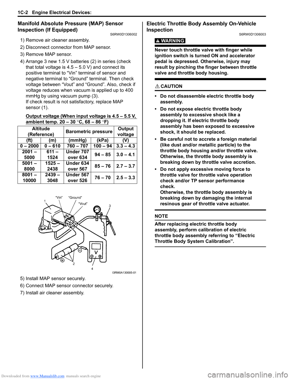
4) Arrange 3 new 1.5 V batteries (2) in series (check
that total voltage is 4.5 – 5.0 V) and connect its
positive terminal to “Vin” terminal of sensor and
negative terminal to “Ground” terminal. Then check
voltage between “Vout” and “Ground”. Also, check if
voltage reduces when vacuum is applied up to 400
mmHg by using vacuum pump (3).
If check result is not satisfactory, replace MAP
sensor (1).
Output voltage (When input voltage is 4.5 – 5.5 V,
ambient temp. 20 – 30 °C, 68 – 86 °F)
5) Install MAP sensor securely.
6) Connect MAP sensor connector securely.
7) Install air cleaner assembly.
Electric Throttle Body Assembly On-Vehicle
Inspection
S6RW0D1306003
WARNING!
Never touch throttle valve with finger while
ignition switch is turned ON and accelerator
pedal is depressed. Otherwise, injury may
result by pinching the finger between throttle
valve and throttle body housing.
CAUTION!
• Do not disassemble electric throttle body
assembly.
• Do not expose electric throttle body
assembly to excessive shock like a
dropping it. If electric throttle body
assembly has been exposed to excessive
shock, it should be replaced.
• Be careful not to accrete a foreign material
(like dust and/or metallic particle) to the
throttle body housing and/or throttle valve.
Otherwise, the throttle body assembly is
breaking down by throttle valve accretion.
• Do not apply excessive moving force to
throttle valve for throttle valve operation
check and/or TP sensor performance
check.
Otherwise, the throttle body assembly is
breaking down by damaging the internal
resinous gear of throttle valve actuator.
NOTE
After replacing electric throttle body
assembly, perform calibration of electric
throttle body assembly referring to “Electric
Throttle Body System Calibration”.
Altitude
(Reference)Barometric pressureOutput
voltage
(ft) (m) (mmHg) (kPa) (V)
0 – 2000 0 – 610 760 – 707 100 – 94 3.3 – 4.3
2001 –
5000611 –
1524Under 707
over 63494 – 85 3.0 – 4.1
5001 –
80001525 –
2438Under 634
over 56785 – 76 2.7 – 3.7
8001 –
100002439 –
3048Under 567
over 52676 – 70 2.5 – 3.3
I3RM0A130005-01
Page 291 of 1556
Downloaded from www.Manualslib.com manuals search engine Engine Mechanical: 1D-9
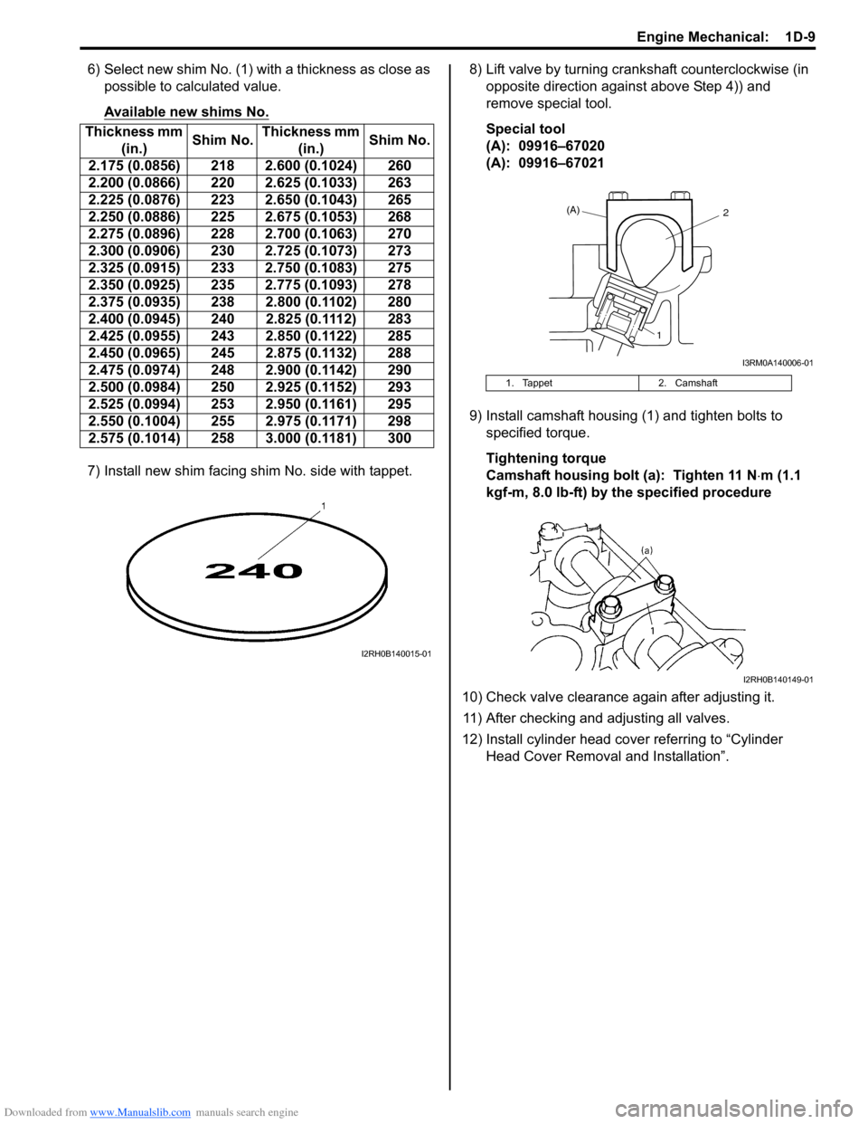
6) Select new shim No. (1) with a thickness as close as
possible to calculated value.
Available new shims No.
7) Install new shim facing shim No. side with tappet.8) Lift valve by turning crankshaft counterclockwise (in
opposite direction against above Step 4)) and
remove special tool.
Special tool
(A): 09916–67020
(A): 09916–67021
9) Install camshaft housing (1) and tighten bolts to
specified torque.
Tightening torque
Camshaft housing bolt (a): Tighten 11 N⋅m (1.1
kgf-m, 8.0 lb-ft) by the specified procedure
10) Check valve clearance again after adjusting it.
11) After checking and adjusting all valves.
12) Install cylinder head cover referring to “Cylinder
Head Cover Removal and Installation”. Thickness mm
(in.)Shim No.Thickness mm
(in.)Shim No.
2.175 (0.0856) 218 2.600 (0.1024) 260
2.200 (0.0866) 220 2.625 (0.1033) 263
2.225 (0.0876) 223 2.650 (0.1043) 265
2.250 (0.0886) 225 2.675 (0.1053) 268
2.275 (0.0896) 228 2.700 (0.1063) 270
2.300 (0.0906) 230 2.725 (0.1073) 273
2.325 (0.0915) 233 2.750 (0.1083) 275
2.350 (0.0925) 235 2.775 (0.1093) 278
2.375 (0.0935) 238 2.800 (0.1102) 280
2.400 (0.0945) 240 2.825 (0.1112) 283
2.425 (0.0955) 243 2.850 (0.1122) 285
2.450 (0.0965) 245 2.875 (0.1132) 288
2.475 (0.0974) 248 2.900 (0.1142) 290
2.500 (0.0984) 250 2.925 (0.1152) 293
2.525 (0.0994) 253 2.950 (0.1161) 295
2.550 (0.1004) 255 2.975 (0.1171) 298
2.575 (0.1014) 258 3.000 (0.1181) 300
I2RH0B140015-01
1. Tappet 2. Camshaft
(A)2
1
I3RM0A140006-01
I2RH0B140149-01
Page 355 of 1556
Downloaded from www.Manualslib.com manuals search engine Engine Mechanical: 1D-73
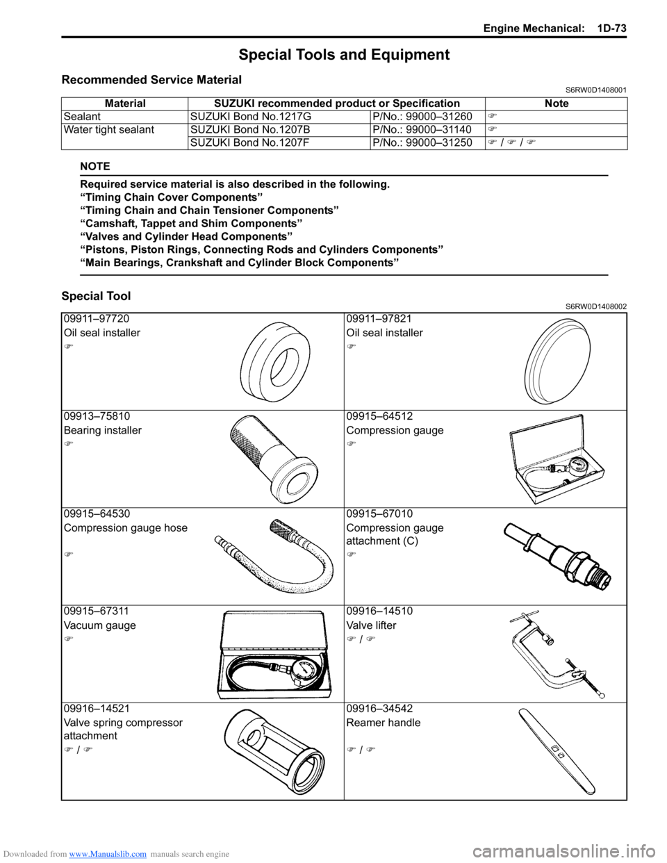
Special Tools and Equipment
Recommended Service MaterialS6RW0D1408001
NOTE
Required service material is also described in the following.
“Timing Chain Cover Components”
“Timing Chain and Chain Tensioner Components”
“Camshaft, Tappet and Shim Components”
“Valves and Cylinder Head Components”
“Pistons, Piston Rings, Connecting Rods and Cylinders Components”
“Main Bearings, Crankshaft and Cylinder Block Components”
Special ToolS6RW0D1408002
Material SUZUKI recommended product or Specification Note
Sealant SUZUKI Bond No.1217G P/No.: 99000–31260)
Water tight sealant SUZUKI Bond No.1207B P/No.: 99000–31140)
SUZUKI Bond No.1207F P/No.: 99000–31250) / ) / )
09911–97720 09911–97821
Oil seal installer Oil seal installer
))
09913–75810 09915–64512
Bearing installer Compression gauge
))
09915–64530 09915–67010
Compression gauge hose Compression gauge
attachment (C)
))
09915–67311 09916–14510
Vacuum gauge Valve lifter
)) / )
09916–14521 09916–34542
Valve spring compressor
attachmentReamer handle
) / )) / )
Page 365 of 1556
Downloaded from www.Manualslib.com manuals search engine Engine Lubrication System: 1E-9
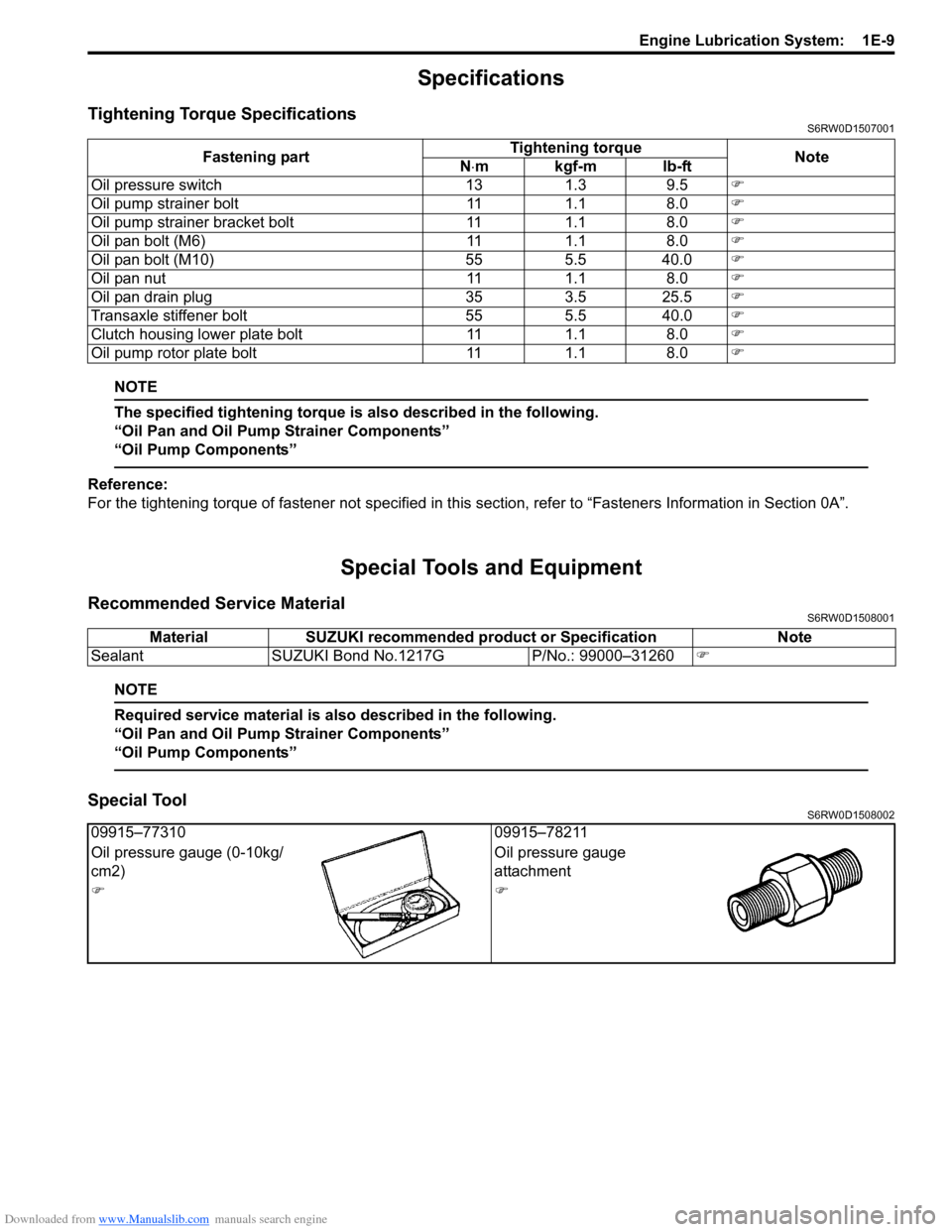
Specifications
Tightening Torque SpecificationsS6RW0D1507001
NOTE
The specified tightening torque is also described in the following.
“Oil Pan and Oil Pump Strainer Components”
“Oil Pump Components”
Reference:
For the tightening torque of fastener not specified in this section, refer to “Fasteners Information in Section 0A”.
Special Tools and Equipment
Recommended Service MaterialS6RW0D1508001
NOTE
Required service material is also described in the following.
“Oil Pan and Oil Pump Strainer Components”
“Oil Pump Components”
Special ToolS6RW0D1508002
Fastening partTightening torque
Note
N⋅mkgf-mlb-ft
Oil pressure switch 13 1.3 9.5)
Oil pump strainer bolt 11 1.1 8.0)
Oil pump strainer bracket bolt 11 1.1 8.0)
Oil pan bolt (M6) 11 1.1 8.0)
Oil pan bolt (M10) 55 5.5 40.0)
Oil pan nut 11 1.1 8.0)
Oil pan drain plug 35 3.5 25.5)
Transaxle stiffener bolt 55 5.5 40.0)
Clutch housing lower plate bolt 11 1.1 8.0)
Oil pump rotor plate bolt 11 1.1 8.0)
Material SUZUKI recommended product or Specification Note
Sealant SUZUKI Bond No.1217G P/No.: 99000–31260)
09915–77310 09915–78211
Oil pressure gauge (0-10kg/
cm2)Oil pressure gauge
attachment
))
Page 377 of 1556
Downloaded from www.Manualslib.com manuals search engine Engine Cooling System: 1F-12
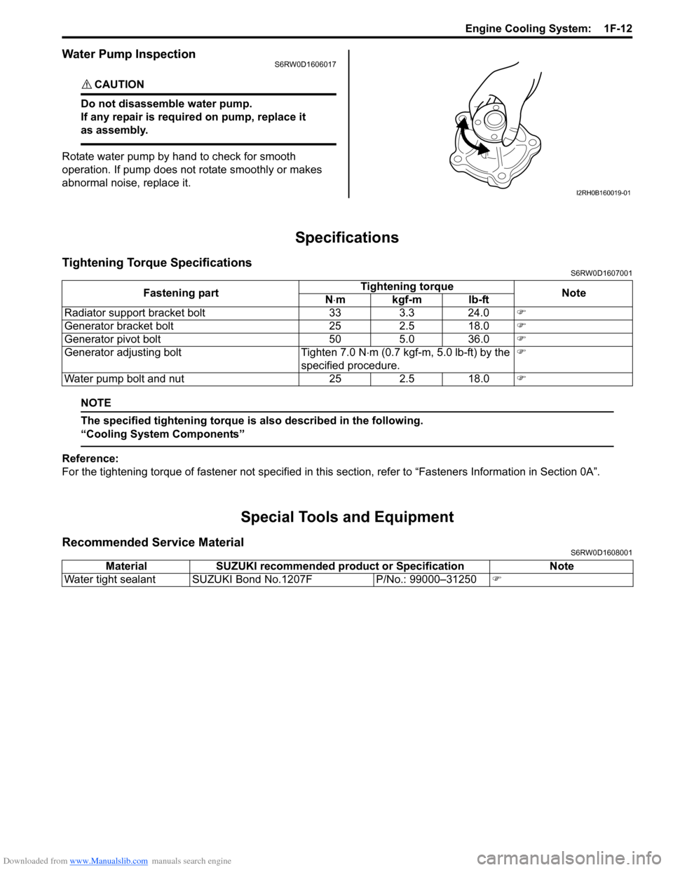
Water Pump InspectionS6RW0D1606017
CAUTION!
Do not disassemble water pump.
If any repair is required on pump, replace it
as assembly.
Rotate water pump by hand to check for smooth
operation. If pump does not rotate smoothly or makes
abnormal noise, replace it.
Specifications
Tightening Torque SpecificationsS6RW0D1607001
NOTE
The specified tightening torque is also described in the following.
“Cooling System Components”
Reference:
For the tightening torque of fastener not specified in this section, refer to “Fasteners Information in Section 0A”.
Special Tools and Equipment
Recommended Service MaterialS6RW0D1608001
I2RH0B160019-01
Fastening partTightening torque
Note
N⋅mkgf-mlb-ft
Radiator support bracket bolt 33 3.3 24.0)
Generator bracket bolt 25 2.5 18.0)
Generator pivot bolt 50 5.0 36.0)
Generator adjusting bolt Tighten 7.0 N⋅m (0.7 kgf-m, 5.0 lb-ft) by the
specified procedure.)
Water pump bolt and nut 25 2.5 18.0)
Material SUZUKI recommended product or Specification Note
Water tight sealant SUZUKI Bond No.1207F P/No.: 99000–31250)
Page 395 of 1556

Downloaded from www.Manualslib.com manuals search engine Fuel System: 1G-18
Special Tools and Equipment
Special ToolS6RW0D1708001
09912–57610 09912–58421
Injector checking tool plate Checking tool set
)This kit includes the
following items. 1. Tool body
and washer, 2. Body plug, 3.
Body attachment-1, 4.
Holder, 5. Return hose and
clamp, 6. Body attachment-2
and washer, 7. Hose
attachment-1, 8. Hose
attachment-2 )
09912–58432 09912–58442
Fuel pressure gauge hose Fuel pressure gauge
This tool is included in fuel
pressure gauge set (09912-
58413). )This tool is included in fuel
pressure gauge set (09912-
58413). )
09912–58490 09919–47020
3-way joint & hose Quick joint remover
))
09930–88530 SUZUKI scan tool (SUZUKI-
SDT)
Injector test lead —
)This kit includes following
items. 1. SUZUKI-SDT 2.
DLC3 cable 3. USB cable 4.
AC/DC power supply 5.
Voltage meter probe 6.
Storage case )
1
2
34
56