relay SUZUKI SX4 2006 1.G Service Workshop Manual
[x] Cancel search | Manufacturer: SUZUKI, Model Year: 2006, Model line: SX4, Model: SUZUKI SX4 2006 1.GPages: 1556, PDF Size: 37.31 MB
Page 13 of 1556
Downloaded from www.Manualslib.com manuals search engine Precautions: 00-6
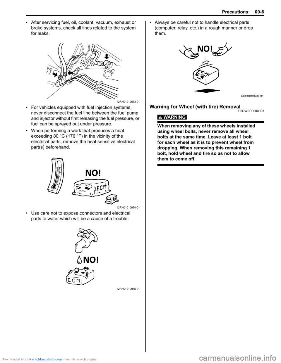
• After servicing fuel, oil, coolant, vacuum, exhaust or
brake systems, check all lines related to the system
for leaks.
• For vehicles equipped with fuel injection systems,
never disconnect the fuel line between the fuel pump
and injector without first releasing the fuel pressure, or
fuel can be sprayed out under pressure.
• When performing a work that produces a heat
exceeding 80 °C (176 °F) in the vicinity of the
electrical parts, remove the heat sensitive electrical
part(s) beforehand.
• Use care not to expose connectors and electrical
parts to water which will be a cause of a trouble.• Always be careful not to handle electrical parts
(computer, relay, etc.) in a rough manner or drop
them.
Warning for Wheel (with tire) RemovalS6RW0D0000003
WARNING!
When removing any of these wheels installed
using wheel bolts, never remove all wheel
bolts at the same time. Leave at least 1 bolt
for each wheel as it is to prevent wheel from
dropping. When removing this remaining 1
bolt, hold wheel and tire so as not to allow
them to come off.
I2RH01010033-01
I2RH01010034-01
I2RH01010035-01
I2RH01010036-01
Page 21 of 1556
Downloaded from www.Manualslib.com manuals search engine Precautions: 00-14
Intermittent and Poor Connection InspectionS6RW0D0006002
Most intermittent are caused by faulty electrical
connections or wiring, although a sticking relay or
solenoid can occasionally be at fault. When checking it
for proper connection, perform careful check of suspect
circuits for:
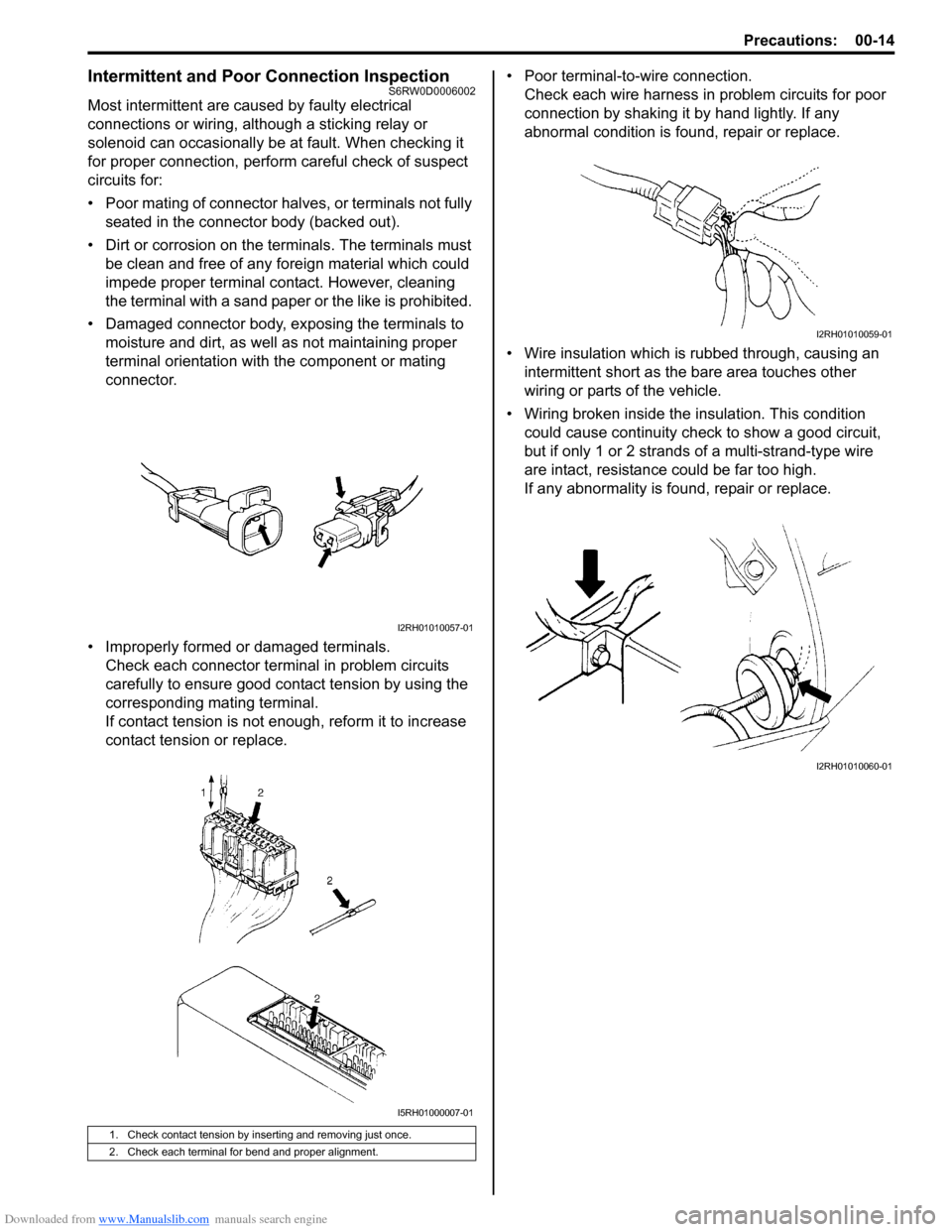
• Poor mating of connector halves, or terminals not fully
seated in the connector body (backed out).
• Dirt or corrosion on the terminals. The terminals must
be clean and free of any foreign material which could
impede proper terminal contact. However, cleaning
the terminal with a sand paper or the like is prohibited.
• Damaged connector body, exposing the terminals to
moisture and dirt, as well as not maintaining proper
terminal orientation with the component or mating
connector.
• Improperly formed or damaged terminals.
Check each connector terminal in problem circuits
carefully to ensure good contact tension by using the
corresponding mating terminal.
If contact tension is not enough, reform it to increase
contact tension or replace.• Poor terminal-to-wire connection.
Check each wire harness in problem circuits for poor
connection by shaking it by hand lightly. If any
abnormal condition is found, repair or replace.
• Wire insulation which is rubbed through, causing an
intermittent short as the bare area touches other
wiring or parts of the vehicle.
• Wiring broken inside the insulation. This condition
could cause continuity check to show a good circuit,
but if only 1 or 2 strands of a multi-strand-type wire
are intact, resistance could be far too high.
If any abnormality is found, repair or replace.
1. Check contact tension by inserting and removing just once.
2. Check each terminal for bend and proper alignment.
I2RH01010057-01
I5RH01000007-01
I2RH01010059-01
I2RH01010060-01
Page 46 of 1556
Downloaded from www.Manualslib.com manuals search engine 1-ii Table of Contents
DTC P0123: Throttle Position Sensor (Main)
Circuit High ..................................................... 1A-89
DTC P0131 / P0132: O2 Sensor (HO2S)
Circuit Low Voltage / High Voltage (Sensor-
1) ..................................................................... 1A-92
DTC P0133: O2 Sensor (HO2S) Circuit Slow
Response (Sensor-1) ...................................... 1A-95
DTC P0134: O2 Sensor (HO2S) Circuit No
Activity Detected (Sensor-1) ........................... 1A-96
DTC P0137 / P0138: O2 Sensor (HO2S)
Circuit Low Voltage / High Voltage (Sensor-
2) ..................................................................... 1A-98
DTC P0140: O2 Sensor (HO2S) Circuit No
Activity Detected (Sensor-2) ......................... 1A-101
DTC P0171 / P0172: Fuel System Too Lean /
Rich ............................................................... 1A-103
DTC P0222: Throttle Position Sensor (Sub)
Circuit Low .................................................... 1A-105
DTC P0223: Throttle Position Sensor (Sub)
Circuit High ................................................... 1A-107
DTC P0300 / P0301 / P0302 / P0303 / P0304:
Random Misfire Detected / Cylinder 1 /
Cylinder 2 / Cylinder 3 / Cylinder 4 Misfire
Detected ........................................................ 1A-110
DTC P0327 / P0328: Knock Sensor Circuit
Low / High ..................................................... 1A-112
DTC P0335: Crankshaft Position (CKP)
Sensor Circuit ............................................... 1A-114
DTC P0340: Camshaft Position (CMP)
Sensor Circuit ............................................... 1A-116
DTC P0401 / P0402: Exhaust Gas
Recirculation Flow Insufficient Detected /
Excessive Detected ...................................... 1A-119
DTC P0403: Exhaust Gas Recirculation
Control Circuit ............................................... 1A-122
DTC P0420: Catalyst System Efficiency
below Threshold ............................................ 1A-124
DTC P0443: Evaporative Emission System
Purge Control Valve Circuit........................... 1A-126
DTC P0462 / P0463: Fuel Level Sensor
Circuit Low / High .......................................... 1A-128
DTC P0480: Fan 1 (Radiator Cooling Fan)
Control Circuit ............................................... 1A-129
DTC P0481: Cooling Fan 2 (A/C Condenser
Fan) Control Circuit ....................................... 1A-131
DTC P0500: Vehicle Speed Sensor (VSS)
Malfunction .................................................... 1A-134
DTC P0532: A/C Refrigerant Pressure
Sensor Circuit Low ........................................ 1A-136
DTC P0533: A/C Refrigerant Pressure
Sensor Circuit High ....................................... 1A-138
DTC P0601 / P0602 / P0607: Internal Control
Module Memory Check Sum Error / Control
Module Programming Error / Control Module
Performance ................................................. 1A-139
DTC P0616: Starter Relay Circuit Low............ 1A-140
DTC P0617: Starter Relay Circuit High ........... 1A-141
DTC P1510: ECM Back-Up Power Supply
Malfunction .................................................... 1A-143DTC P2101: Throttle Actuator Control Motor
Circuit Range / Performance ......................... 1A-144
DTC P2102: Throttle Actuator Control Motor
Circuit Low .................................................... 1A-146
DTC P2103: Throttle Actuator Control Motor
Circuit High.................................................... 1A-147
DTC P2111: Throttle Actuator Control System
- Stuck Open ................................................. 1A-148
DTC P2119: Throttle Actuator Control Throttle
Body Range / Performance ........................... 1A-149
DTC P2122: Pedal Position Sensor (Main)
Circuit Low Input ........................................... 1A-151
DTC P2123: Pedal Position Sensor (Main)
Circuit High Input........................................... 1A-153
DTC P2127: Pedal Position Sensor (Sub)
Circuit Low Input ........................................... 1A-155
DTC P2128: Pedal Position Sensor (Sub)
Circuit High Input........................................... 1A-158
DTC P2135: Throttle Position Sensor (Main /
Sub) Voltage Correlation ............................... 1A-160
DTC P2138: Pedal Position Sensor (Main /
Sub) Voltage Correlation ............................... 1A-163
DTC P2227 / P2228 / P2229: Barometric
Pressure Circuit Malfunction ......................... 1A-165
DTC U0073: Control Module Communication
Bus Off .......................................................... 1A-166
DTC U0101: Lost Communication with TCM .. 1A-166
DTC U0121: Lost Communication with ABS
Control Module .............................................. 1A-166
DTC U0140: Lost Communication with Body
Control Module .............................................. 1A-166
Troubleshooting for CAN-DTC ........................ 1A-167
Inspection of ECM and Its Circuits .................. 1A-172
ECM Power and Ground Circuit Check........... 1A-193
Fuel Injector Circuit Check .............................. 1A-196
Fuel Pump and Its Circuit Check..................... 1A-198
Fuel Pressure Check....................................... 1A-201
A/C Condenser Cooling Fan Control System
Inspection ...................................................... 1A-202
A/C System Circuits Check ............................. 1A-205
Electric Load Signal Circuit Check .................. 1A-209
Radiator Cooling Fan Control System Check . 1A-211
Repair Instructions ..........................................1A-212
Idle Speed and IAC Throttle Valve Opening
Inspection ...................................................... 1A-212
Special Tools and Equipment .........................1A-213
Special Tool .................................................... 1A-213
Aux. Emission Control Devices ............. 1B-1
Diagnostic Information and Procedures ............1B-1
EGR System Inspection (If Equipped) ................ 1B-1
Repair Instructions ..............................................1B-1
EVAP Canister Purge Inspection ........................ 1B-1
EVAP Canister Purge Valve and Its Circuit
Inspection .......................................................... 1B-1
Vacuum Passage Inspection............................... 1B-2
Vacuum Hose Inspection .................................... 1B-3
EVAP Canister Purge Valve Inspection .............. 1B-3
EVAP Canister Inspection ................................... 1B-4
Page 47 of 1556
Downloaded from www.Manualslib.com manuals search engine Table of Contents 1-iii
EGR Valve Removal and Installation (If
Equipped).......................................................... 1B-4
EGR Valve Inspection (If Equipped) ................... 1B-4
PCV Hose Inspection .......................................... 1B-5
PCV Valve Inspection ......................................... 1B-5
Special Tools and Equipment ............................. 1B-5
Special Tool ........................................................ 1B-5
Engine Electrical Devices ....................... 1C-1
Repair Instructions .............................................. 1C-1
Engine Control Module (ECM) Removal and
Installation ......................................................... 1C-1
Manifold Absolute Pressure (MAP) Sensor
Inspection (If Equipped) .................................... 1C-2
Electric Throttle Body Assembly On-Vehicle
Inspection.......................................................... 1C-2
Electric Throttle Body System Calibration ........... 1C-5
Accelerator Pedal Position (APP) Sensor
Assembly On-Vehicle Inspection ...................... 1C-5
Accelerator Pedal Position (APP) Sensor
Assembly Removal and Installation .................. 1C-5
Accelerator Pedal Position (APP) Sensor
Assembly Inspection ......................................... 1C-6
Engine Coolant Temperature (ECT) Sensor
Removal and Installation................................... 1C-7
Engine Coolant Temperature (ECT) Sensor
Inspection.......................................................... 1C-7
Heated Oxygen Sensor (HO2S-1 and HO2S-
2) Heater On-Vehicle Inspection (If
Equipped).......................................................... 1C-8
Heated Oxygen Sensor (HO2S-1 and HO2S-
2) Removal and Installation (If Equipped) ......... 1C-8
Camshaft Position (CMP) Sensor Removal
and Installation .................................................. 1C-9
Camshaft Position (CMP) Sensor Inspection ...... 1C-9
Crankshaft Position (CKP) Sensor Removal
and Installation ................................................ 1C-10
Crankshaft Position (CKP) Sensor Inspection .. 1C-11
Knock Sensor Removal and Installation ........... 1C-11
Main Relay, Fuel Pump Relay, Starting Motor
Control Relay, Throttle Actuator Control
Relay and Radiator Cooling Fan Relay
Inspection........................................................ 1C-12
Mass Air Flow (MAF) and Intake Air
Temperature (IAT) Sensor On-Vehicle
Inspection........................................................ 1C-12
Mass Air Flow (MAF) and Intake Air
Temperature (IAT) Sensor Removal and
Installation ....................................................... 1C-13
Intake Air Temperature (IAT) Sensor
Inspection........................................................ 1C-13
Specifications..................................................... 1C-14
Tightening Torque Specifications ...................... 1C-14
Engine Mechanical .................................. 1D-1
General Description ............................................. 1D-1
Engine Construction Description ......................... 1D-1
Camshaft Position Control (VVT Variable
Valve Timing) System Description .................... 1D-3Diagnostic Information and Procedures ............1D-5
Compression Check ............................................1D-5
Engine Vacuum Check........................................1D-6
Valve Lash (Clearance) Inspection .....................1D-7
Repair Instructions ............................................1D-10
Air Intake System Components.........................1D-10
Air Cleaner Filter Removal and Installation .......1D-10
Air Cleaner Filter Inspection and Cleaning........1D-10
Air Cleaner Assembly Removal and
Installation .......................................................1D-11
Cylinder Head Cover Removal and
Installation .......................................................1D-11
Throttle Body and Intake Manifold
Components ....................................................1D-13
Throttle Body On-Vehicle Inspection.................1D-14
Electric Throttle Body Assembly Removal and
Installation .......................................................1D-14
Throttle Body Cleaning......................................1D-14
Intake Manifold Removal and Installation .........1D-15
Engine Mountings Components ........................1D-16
Engine Assembly Removal and Installation ......1D-17
Timing Chain Cover Components .....................1D-22
Timing Chain Cover Removal and Installation ..1D-23
Timing Chain Cover Inspection .........................1D-25
Oil Control Valve Removal and Installation
(For Engine with VVT) .....................................1D-26
Oil Control Valve Inspection (For Engine with
VVT) ................................................................1D-26
Timing Chain and Chain Tensioner
Components ....................................................1D-27
Timing Chain and Chain Tensioner Removal
and Installation ................................................1D-27
Timing Chain and Chain Tensioner Inspection ..1D-31
Camshaft, Tappet and Shim Components ........1D-32
Camshaft, Tappet and Shim Removal and
Installation .......................................................1D-33
Camshaft, Tappet and Shim Inspection ............1D-36
Valves and Cylinder Head Components ...........1D-39
Valves and Cylinder Head Removal and
Installation .......................................................1D-40
Valves and Cylinder Head Disassembly and
Assembly.........................................................1D-42
Valves and Valve Guides Inspection.................1D-45
Cylinder Head Inspection ..................................1D-47
Valve Spring Inspection ....................................1D-48
Pistons, Piston Rings, Connecting Rods and
Cylinders Components ....................................1D-49
Pistons, Piston Rings, Connecting Rods and
Cylinders Removal and Installation .................1D-49
Pistons, Piston Rings, Connecting Rods and
Cylinders Disassembly and Assembly ............1D-51
Cylinders, Pistons and Piston Rings
Inspection ........................................................1D-52
Piston Pins and Connecting Rods Inspection ...1D-54
Crank Pin and Connecting Rod Bearings
Inspection ........................................................1D-55
Main Bearings, Crankshaft and Cylinder
Block Components ..........................................1D-59
Main Bearings, Crankshaft and Cylinder
Block Removal and Installation .......................1D-60
Page 48 of 1556
Downloaded from www.Manualslib.com manuals search engine 1-iv Table of Contents
Crankshaft Inspection .......................................1D-63
Main Bearings Inspection ..................................1D-65
Sensor Plate Inspection ....................................1D-70
Rear Oil Seal Inspection ...................................1D-70
Flywheel Inspection...........................................1D-70
Cylinder Block Inspection ..................................1D-70
Specifications .....................................................1D-71
Tightening Torque Specifications ......................1D-71
Special Tools and Equipment ...........................1D-73
Recommended Service Material .......................1D-73
Special Tool ......................................................1D-73
Engine Lubrication System.....................1E-1
General Description ............................................. 1E-1
Engine Lubrication Description ........................... 1E-1
Diagnostic Information and Procedures ............ 1E-2
Oil Pressure Check ............................................. 1E-2
Repair Instructions .............................................. 1E-3
Oil Pan and Oil Pump Strainer Components....... 1E-3
Oil Pan and Oil Pump Strainer Removal and
Installation ......................................................... 1E-4
Oil Pan and Oil Pump Strainer Cleaning ............. 1E-5
Oil Pump Components ........................................ 1E-6
Oil Pump Removal and Installation ..................... 1E-6
Oil Pump Disassembly and Reassembly ............ 1E-6
Oil Pump Inspection ............................................ 1E-7
Specifications ....................................................... 1E-9
Tightening Torque Specifications ........................ 1E-9
Special Tools and Equipment ............................. 1E-9
Recommended Service Material ......................... 1E-9
Special Tool ........................................................ 1E-9
Engine Cooling System ........................... 1F-1
General Description ............................................. 1F-1
Cooling System Description ................................ 1F-1
Coolant Description ............................................. 1F-1
Schematic and Routing Diagram ........................ 1F-2
Coolant Circulation .............................................. 1F-2
Diagnostic Information and Procedures ............ 1F-3
Engine Cooling Symptom Diagnosis ................... 1F-3
Repair Instructions .............................................. 1F-4
Cooling System Components.............................. 1F-4
Coolant Level Check ........................................... 1F-5
Engine Cooling System Inspection and
Cleaning ............................................................ 1F-5
Cooling System Draining..................................... 1F-5
Cooling System Flush and Refill ......................... 1F-6
Cooling Water Pipes or Hoses Removal and
Installation ......................................................... 1F-6
Thermostat Removal and Installation.................. 1F-7
Thermostat Inspection......................................... 1F-7
Radiator Cooling Fan Assembly On-Vehicle
Inspection .......................................................... 1F-8
Radiator Cooling Fan Relay Inspection............... 1F-8
Radiator Cooling Fan Assembly Removal and
Installation ......................................................... 1F-8
Radiator Cooling Fan Disassembly and
Reassembly ...................................................... 1F-9
Radiator On-Vehicle Inspection and Cleaning .... 1F-9Radiator Removal and Installation ...................... 1F-9
Water Pump / Generator Drive Belt Tension
Inspection and Adjustment.............................. 1F-10
Water Pump / Generator Drive Belt Removal
and Installation ................................................ 1F-10
Water Pump Removal and Installation .............. 1F-11
Water Pump Inspection ..................................... 1F-12
Specifications ..................................................... 1F-12
Tightening Torque Specifications ...................... 1F-12
Special Tools and Equipment ........................... 1F-12
Recommended Service Material ....................... 1F-12
Fuel System ............................................. 1G-1
Precautions .......................................................... 1G-1
Precautions on Fuel System Service ................. 1G-1
General Description ............................................ 1G-2
Fuel System Description .................................... 1G-2
Fuel Delivery System Description ...................... 1G-2
Fuel Pump Description ....................................... 1G-2
Schematic and Routing Diagram ....................... 1G-3
Fuel Delivery System Diagram........................... 1G-3
Diagnostic Information and Procedures ........... 1G-3
Fuel Pressure Inspection ................................... 1G-3
Fuel Cut Operation Inspection ........................... 1G-4
Repair Instructions ............................................. 1G-5
Fuel System Components .................................. 1G-5
Fuel Hose Disconnecting and Reconnecting ..... 1G-6
Fuel Pressure Relief Procedure ......................... 1G-7
Fuel Leakage Check Procedure......................... 1G-8
Fuel Lines On-Vehicle Inspection ...................... 1G-8
Fuel Pipe Removal and Installation.................... 1G-8
Fuel Injector On-Vehicle Inspection ................... 1G-9
Fuel Injector Removal and Installation ............... 1G-9
Fuel Injector Inspection .................................... 1G-10
Fuel Filler Cap Inspection ................................ 1G-12
Fuel Tank Inlet Valve Removal and
Installation ...................................................... 1G-12
Fuel Tank Inlet Valve Inspection ...................... 1G-12
Fuel Tank Removal and Installation ................. 1G-13
Fuel Tank Inspection ........................................ 1G-14
Fuel Tank Purging Procedure .......................... 1G-15
Fuel Pump On-Vehicle Inspection.................... 1G-15
Fuel Pump Assembly Removal and
Installation ...................................................... 1G-15
Main Fuel Level Sensor Removal and
Installation ...................................................... 1G-16
Fuel Pump Inspection ...................................... 1G-17
Specifications .................................................... 1G-17
Tightening Torque Specifications ..................... 1G-17
Special Tools and Equipment .......................... 1G-18
Special Tool ..................................................... 1G-18
Ignition System ........................................ 1H-1
General Description .............................................1H-1
Ignition System Construction ..............................1H-1
Schematic and Routing Diagram ........................1H-2
Ignition System Wiring Circuit Diagram...............1H-2
Component Location ...........................................1H-3
Ignition System Components Location................1H-3
Page 52 of 1556
Downloaded from www.Manualslib.com manuals search engine 1A-2 Engine General Information and Diagnosis:
• When checking ECM for DTC, keep in mind that DTC
is displayed on the scan tool as follows depending on
the scan tool used.
– SUZUKI scan tool displays DTC detected by ECM.
– CAN communication OBD generic scan tool
displays DTC detected by each of ECM and TCM
(for A/T model) simultaneously.
• Priorities for diagnosing troubles
If two or more DTCs are stored, proceed to the DTC
flow which has been detected earliest in the order and
follow the instruction in that flow.
If no instructions are given, troubleshoot DTCs
according to the following priorities.
a. DTCs other than DTC P0171 / P0172 (Fuel
system too lean / too rich), DTC P0300 / P0301 /
P0302 / P0303 / P0304 (Misfire detected) and
DTC P0401 / P0402 (EGR flow malfunction)
b. DTC P0171 / P0172 (Fuel system too lean / too
rich) and DTC P0401 / P0402 (EGR flow
malfunction)
c. DTC P0300 / P0301 / P0302 / P0303 / P0304
(Misfire detected)
• Be sure to read “Precautions for Electrical Circuit
Service in Section 00” before inspection and observe
what is written there.
• ECM replacement:
When substituting a known-good ECM, check for the
following conditions. Neglecting this check may cause
damage to a known-good ECM.
– Resistance value of all relays, actuators is as
specified respectively.
– MAP sensor, A/C refrigerant pressure sensor (if
equipped with A/C), accelerator pedal position
(APP) sensor and TP sensor are in good condition
and none of power circuits of these sensors is
shorted to ground.
• Communication of ECM, BCM, combination meter,
keyless start control module (if equipped with keyless
start control system), 4WD control module (if
equipped), TCM (for A/T model) and ABS control
module, is established by CAN (Controller Area
Network). (For more detail of CAN communication for
ECM, refer to “CAN Communication System
Description”). Therefore, handle CAN communication
line with care referring to “Precaution for CAN
Communication System in Section 00”.
• Immobilizer transponder code registration after
replacing ECM (Immobilizer model)
When ECM is replaced with new one or with another
one, make sure to register immobilizer transponder
code to ECM correctly according to “Procedure after
ECM Replacement in Section 10C”.Precautions for DTC TroubleshootingS6RW0D1100003
• Before performed trouble shooting, be sure to read
the “Precautions of ECM Circuit Inspection”.
• When measuring circuit voltage, resistance and/or
pulse signal at ECM connector, connect the special
tool to ECM and/or the ECM connectors referring to
“Inspection of ECM and Its Circuits”.
• Upon completion of inspection and repair work,
perform “DTC Confirmation Procedure” and confirm
that the trouble has been corrected.
Precautions of ECM Circuit InspectionS6RW0D1100004
• ECM connectors are waterproofed. Each terminal of
the ECM connectors is sealed up with the grommet.
Therefore, when measuring circuit voltage, resistance
and/or pulse signal at ECM connector, do not insert
the tester’s probe into the sealed terminal at the
harness side. When measuring circuit voltage,
resistance and/or pulse signal at ECM connector,
connect the special tool to the ECM connectors. And,
insert the tester’s probe into the special tool’s
connectors at the harness side, and then measure
voltage, resistance and/or pulse signal. Or, ECM and
its circuits may be damaged by water.
• Wire colors of the special tool’s connectors are
different from the ones of the ECM connectors.
However, the circuit arrangement of the special tool’s
connectors is same as the one of the ECM
connectors. Therefore, measure circuit voltage and
resistance by identifying the terminal location subject
to the measurement.
Precautions of Electric Throttle Body System
Calibration
S6RW0D1100005
After performing one of works described below, it is
necessary to re-register the completely closed throttle
valve reference position stored in memory of ECM. (For
detailed information, refer to “Description of Electric
Throttle Body System Calibration”.) For the procedure to
register such data in ECM, refer to “Electric Throttle
Body System Calibration in Section 1C”.
• To shut off backup power of ECM for such purposes of
battery replacement or “DOME” fuse removal
• To erase DTCs P0122, P0123, P0222, P0223, P2101,
P2102, P2103, P2111, P2112, P2119 and/or P2135
• To replace ECM
• To replace throttle body and/or accelerator pedal
position (APP) sensor assembly
Page 61 of 1556
Downloaded from www.Manualslib.com manuals search engine Engine General Information and Diagnosis: 1A-11
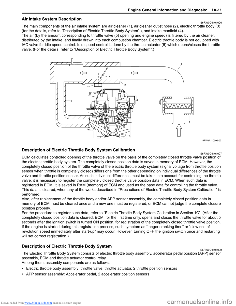
Air Intake System DescriptionS6RW0D1101006
The main components of the air intake system are air cleaner (1), air cleaner outlet hose (2), electric throttle body (3)
(for the details, refer to “Description of Electric Throttle Body System”.), and intake manifold (4).
The air (by the amount corresponding to throttle valve (5) opening and engine speed) is filtered by the air cleaner,
distributed by the intake, and finally drawn into each combustion chamber. Electric throttle body is not equipped with
IAC valve for idle speed control. Idle speed control is done by the throttle actuator (6) which opens/closes the throttle
valve. (For the details, refer to “Description of Electric Throttle Body System”.)
Description of Electric Throttle Body System CalibrationS6RW0D1101007
ECM calculates controlled opening of the throttle valve on the basis of the completely closed throttle valve position of
the electric throttle body system. The completely closed position data is saved in memory of ECM. However, the
completely closed position of the throttle valve of the electric throttle body system (signal voltage from throttle position
sensor when throttle is completely closed) differs one from the other depending on individual differences of the throttle
valve and throttle position sensor. As such individual differences must be taken into account for controlling the throttle
valve, it is necessary to register the completely closed throttle valve position data in ECM. When such data is
registered in ECM, it is saved in RAM (memory) of ECM and used as the base data for controlling the throttle valve.
This data is cleared, when any of the works described in “Precautions of Electric Throttle Body System Calibration” is
performed.
Also, after replacement of the throttle body and/or APP sensor assembly, the completely closed position data in
memory of ECM must be cleared once and a new one must be registered, or ECM cannot judge the complete closure
position properly.
For the procedure to register such data, refer to “Electric Throttle Body System Calibration in Section 1C”. (After the
completely closed position data is cleared, ECM, for the first time only, opens and closes the throttle valve for about 5
seconds after the ignition switch is turned ON position, for registration of the completely closed throttle valve position.
If the engine is started during this registration process, such symptom as “longer cranking time” or “slow rise of
revolution speed immediately after start-up” may occur. However, turning OFF the ignition switch once and restarting
will set correct registration.)
Description of Electric Throttle Body SystemS6RW0D1101009
The Electric Throttle Body System consists of electric throttle body assembly, accelerator pedal position (APP) sensor
assembly, ECM and throttle actuator control relay.
Among them, assembly components are as follows.
• Electric throttle body assembly: throttle valve, throttle actuator, 2 throttle position sensors
• APP sensor assembly: Accelerator pedal, 2 accelerator position sensors
42
1
3
5
6
I5RW0A110006-02
Page 62 of 1556
Downloaded from www.Manualslib.com manuals search engine 1A-12 Engine General Information and Diagnosis:
Operation Description
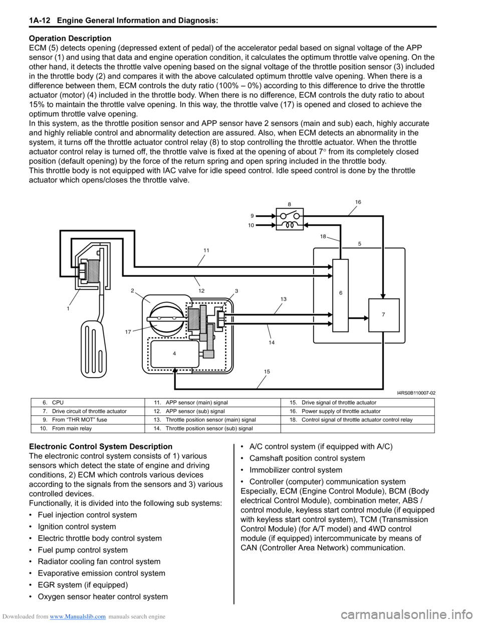
ECM (5) detects opening (depressed extent of pedal) of the accelerator pedal based on signal voltage of the APP
sensor (1) and using that data and engine operation condition, it calculates the optimum throttle valve opening. On the
other hand, it detects the throttle valve opening based on the signal voltage of the throttle position sensor (3) included
in the throttle body (2) and compares it with the above calculated optimum throttle valve opening. When there is a
difference between them, ECM controls the duty ratio (100% – 0%) according to this difference to drive the throttle
actuator (motor) (4) included in the throttle body. When there is no difference, ECM controls the duty ratio to about
15% to maintain the throttle valve opening. In this way, the throttle valve (17) is opened and closed to achieve the
optimum throttle valve opening.
In this system, as the throttle position sensor and APP sensor have 2 sensors (main and sub) each, highly accurate
and highly reliable control and abnormality detection are assured. Also, when ECM detects an abnormality in the
system, it turns off the throttle actuator control relay (8) to stop controlling the throttle actuator. When the throttle
actuator control relay is turned off, the throttle valve is fixed at the opening of about 7° from its completely closed
position (default opening) by the force of the return spring and open spring included in the throttle body.
This throttle body is not equipped with IAC valve for idle speed control. Idle speed control is done by the throttle
actuator which opens/closes the throttle valve.
Electronic Control System Description
The electronic control system consists of 1) various
sensors which detect the state of engine and driving
conditions, 2) ECM which controls various devices
according to the signals from the sensors and 3) various
controlled devices.
Functionally, it is divided into the following sub systems:
• Fuel injection control system
• Ignition control system
• Electric throttle body control system
• Fuel pump control system
• Radiator cooling fan control system
• Evaporative emission control system
• EGR system (if equipped)
• Oxygen sensor heater control system• A/C control system (if equipped with A/C)
• Camshaft position control system
• Immobilizer control system
• Controller (computer) communication system
Especially, ECM (Engine Control Module), BCM (Body
electrical Control Module), combination meter, ABS /
control module, keyless start control module (if equipped
with keyless start control system), TCM (Transmission
Control Module) (for A/T model) and 4WD control
module (if equipped) intercommunicate by means of
CAN (Controller Area Network) communication.
4 12
1735
6
7 8
9
10
11
12
13
14
1516
18
I4RS0B110007-02
6. CPU 11. APP sensor (main) signal 15. Drive signal of throttle actuator
7. Drive circuit of throttle actuator 12. APP sensor (sub) signal 16. Power supply of throttle actuator
9. From “THR MOT” fuse 13. Throttle position sensor (main) signal 18. Control signal of throttle actuator control relay
10. From main relay 14. Throttle position sensor (sub) signal
Page 64 of 1556
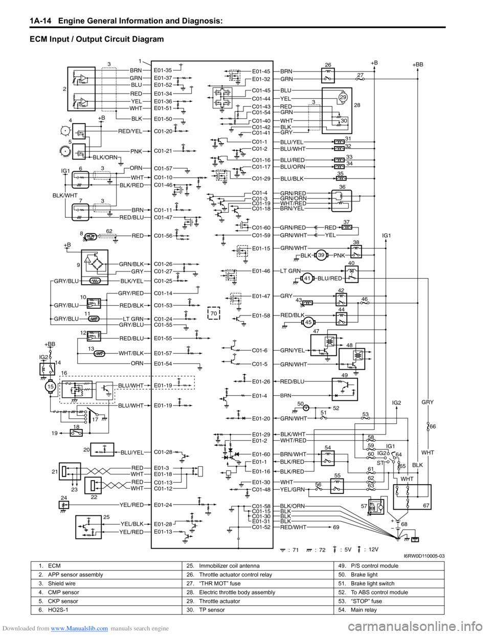
Downloaded from www.Manualslib.com manuals search engine 1A-14 Engine General Information and Diagnosis:
ECM Input / Output Circuit Diagram
51 50
+B
54
IG1+BB
ST64
65
67
BLK/WHTWHT/RED
BRN/WHTBLK/RED
BLK/RED
57
: 71
: 72 : 5V : 12V68 IG1
BLK
WHT
GRY
YEL/GRNWHT
66
58
61
62
63 55
70
60 59
53
WHT
4+B
5
PNK
RED/YEL
BLK/ORN
C01-20
C01-21
8RED62C01-56
13WHT/BLKE01-57
ORNE01-54
21
23WHTRED
WHTRED
22
E01-3E01-18
C01-13C01-12
YEL/RED 24E01-24
YEL/BLK
YEL/RED 25E01-28E01-13
E01-30
E01-16
E01-60E01-1
E01-29
GRN/WHTE01-20
C01-48
E01-2
GRN/YEL47
48
GRN/WHTC01-5
C01-6
44
45RED/BLKE01-58
42
43GRY46E01-47
40LT GRN41BLU/REDE01-46
38
39
PNKBLKGRN/WHTE01-15
GRN/REDGRN/WHT37YELREDC01-59C01-60
35BLU/BLKC01-29
31
32
33
34BLU/YELBLU/WHT
BLU/REDBLU/ORNC01-17C01-16
C01-1C01-2
BLK/ORNBLKC01-30
C01-58C01-15
E01-31BLKBLK
49RED/BLU
BRNE01-4
E01-26 9
GRY
BLK/YELGRY/BLU
GRN/BLKC01-26C01-27
C01-25 +B
IG16
7WHT
BRNRED/BLU
BLK/WHT
3 3
ORN
BLK/RED
C01-57
C01-10
C01-11
C01-46
C01-47
GRY/REDC01-14
11LT GRNGRY/BLUGRY/BLU12RED/BLU
C01-55
E01-55
C01-24
10
RED/BLKGRY/BLUC01-53
IG2
IG2
69RED/WHTC01-52
26
RED
BRNGRN
BLU
GRN
WHTBLK
28
30 2927
3YEL
GRYC01-41C01-42C01-40
C01-43C01-44
C01-45
E01-45E01-32
C01-54
BRN/YELWHT/RED
GRN/REDGRN/ORN
C01-18C01-1936C01-3C01-4
56
1
52
IG2+BB
BLU/WHT
BLU/WHT
14
15
17
16
E01-19
E01-19
18
19
BRNGRNBLU
REDYELWHT
E01-353
BLK
E01-37E01-52
E01-34E01-36E01-51
E01-50
2
20BLU/YELC01-28
I6RW0D110005-03
1. ECM 25. Immobilizer coil antenna 49. P/S control module
2. APP sensor assembly 26. Throttle actuator control relay 50. Brake light
3. Shield wire 27. “THR MOT” fuse 51. Brake light switch
4. CMP sensor 28. Electric throttle body assembly 52. To ABS control module
5. CKP sensor 29. Throttle actuator 53. “STOP” fuse
6. HO2S-1 30. TP sensor 54. Main relay
Page 65 of 1556
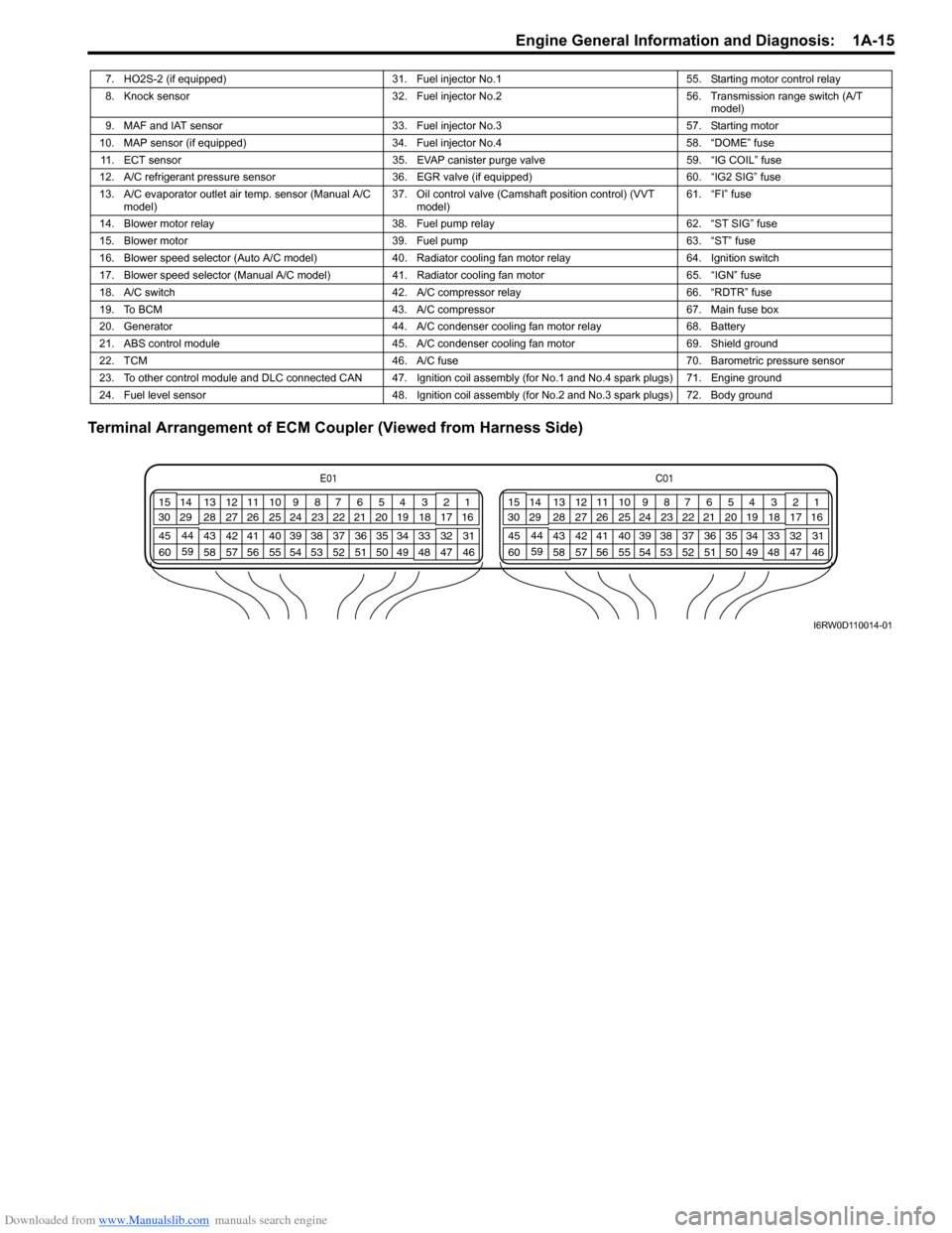
Downloaded from www.Manualslib.com manuals search engine Engine General Information and Diagnosis: 1A-15
Terminal Arrangement of ECM Coupler (Viewed from Harness Side)
7. HO2S-2 (if equipped) 31. Fuel injector No.1 55. Starting motor control relay
8. Knock sensor 32. Fuel injector No.2 56. Transmission range switch (A/T
model)
9. MAF and IAT sensor 33. Fuel injector No.3 57. Starting motor
10. MAP sensor (if equipped) 34. Fuel injector No.4 58. “DOME” fuse
11. ECT sensor 35. EVAP canister purge valve 59. “IG COIL” fuse
12. A/C refrigerant pressure sensor 36. EGR valve (if equipped) 60. “IG2 SIG” fuse
13. A/C evaporator outlet air temp. sensor (Manual A/C
model)37. Oil control valve (Camshaft position control) (VVT
model)61. “FI” fuse
14. Blower motor relay 38. Fuel pump relay 62. “ST SIG” fuse
15. Blower motor 39. Fuel pump 63. “ST” fuse
16. Blower speed selector (Auto A/C model) 40. Radiator cooling fan motor relay 64. Ignition switch
17. Blower speed selector (Manual A/C model) 41. Radiator cooling fan motor 65. “IGN” fuse
18. A/C switch 42. A/C compressor relay 66. “RDTR” fuse
19. To BCM 43. A/C compressor 67. Main fuse box
20. Generator 44. A/C condenser cooling fan motor relay 68. Battery
21. ABS control module 45. A/C condenser cooling fan motor 69. Shield ground
22. TCM 46. A/C fuse 70. Barometric pressure sensor
23. To other control module and DLC connected CAN 47. Ignition coil assembly (for No.1 and No.4 spark plugs) 71. Engine ground
24. Fuel level sensor 48. Ignition coil assembly (for No.2 and No.3 spark plugs) 72. Body ground
E01C01
3 4
18 19 5 6 7 10 11
17 20
47 46 49 50 51 21 22
5216 259
24 14
29
55 57 54 53 59
60 582
26 27 28 15
30
56 4832 31 34 35 36 37 40 42 39 38 44
45 43 41 331 12 13
238 3 4
18 19 5 6 7 10 11
17 20
47 46 49 50 51 21 22
5216 259
24 14
29
55 57 54 53 59
60 582
26 27 28 15
30
56 4832 31 34 35 36 37 40 42 39 38 44
45 43 41 331 12 13
238
I6RW0D110014-01