Cam angle SUZUKI SX4 2006 1.G Service Workshop Manual
[x] Cancel search | Manufacturer: SUZUKI, Model Year: 2006, Model line: SX4, Model: SUZUKI SX4 2006 1.GPages: 1556, PDF Size: 37.31 MB
Page 285 of 1556
Downloaded from www.Manualslib.com manuals search engine Engine Mechanical: 1D-3
Camshaft Position Control (VVT Variable Valve Timing) System DescriptionS6RW0D1401002
System Description
The VVT system is an electronic control system which continuously vary and optimize the intake valve timing in
response to the engine operating condition.
The optimized intake valve timing produce such an air intake with high efficiency that both the higher power generation
and lower fuel consumption can be attained in the whole engine speed range from low to high. In the area of the
average engine load, low emission of nitrogen oxides (NOx) and high fuel efficiency can also be attained by making
the valve opening overlap between the intake and exhaust valves longer.
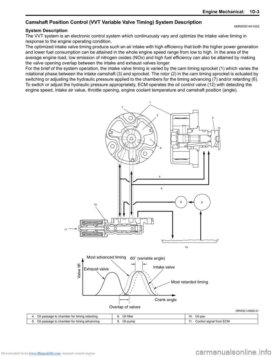
For the brief of the system operation, the intake valve timing is varied by the cam timing sprocket (1) which varies the
rotational phase between the intake camshaft (3) and sprocket. The rotor (2) in the cam timing sprocket is actuated by
switching or adjusting the hydraulic pressure applied to the chambers for the timing advancing (7) and/or retarding (6).
To switch or adjust the hydraulic pressure appropriately, ECM operates the oil control valve (12) with detecting the
engine speed, intake air value, throttle opening, engine coolant temperature and camshaft position (angle).
1
4
5
10
8
9
2
7
6
12
11
3
60˚ (variable angle)
Most retarded timing Most advanced timing
Exhaust valveIntake valve
Crank angle
Overlap of valves
Valve lift
I5RW0C140002-01
4. Oil passage to chamber for timing retarding 8. Oil filter 10. Oil pan
5. Oil passage to chamber for timing advancing 9. Oil pump 11. Control signal from ECM
Page 310 of 1556

Downloaded from www.Manualslib.com manuals search engine 1D-28 Engine Mechanical:
Installation
CAUTION!
After timing chain is removed, never turn
crankshaft and camshafts independently
more than such an extent (“a”, “b”) as shown
in figure.
If turned, interference may occur between
piston and valves and valves themselves,
and parts related to piston and valves may be
damaged.
1) Check that match marks (1) on intake and exhaust
camshaft timing sprockets are in match with notches
(2) on cylinder head as shown in figure.
2) Set key (3) and turn crankshaft to position key on
upside of crankshaft.3) Install timing chain to camshaft timing sprockets as
follows.
• For engine with VVT
Install timing chain by aligning dark blue plates (1)
of timing chain and triangle mark (2) on camshaft
timing sprockets.
• For engine without VVT
Install timing chain by aligning dark blue plates (1)
of timing chain and circle mark (5) on intake
camshaft timing sprocket and triangle mark (5) on
exhaust camshaft timing sprocket.
4) Fit crankshaft timing sprocket to timing chain by
aligning gold plate (3) of timing chain and circle mark
(4) on crankshaft timing sprocket. Then install
crankshaft timing sprocket fitted with chain to
crankshaft.
“a”: 90°4. Camshaft (IN and EX) allowable turning range.
By marks on camshaft timing sprocket within 15° from notches
on cylinder head on both right and left.
“b”: 15°5. Crankshaft allowable turning range.
By key on crankshaft, within 90° from top on both right and left.
“a”
“b” “b”“b” “b”
“a”
1
12
4
3
5
I4RS0A140021-01
[A]: For engine with VVT [B]: For engine without VVT
34
1 1
Approx. 60 Approx. 30 [A]
1
Appro x. 60 Approx. 30 1 [B]
2
2
2
5
I5RW0C140018-01
Page 311 of 1556

Downloaded from www.Manualslib.com manuals search engine Engine Mechanical: 1D-29
5) Apply engine oil to sliding surface of timing chain
No.1 guide (1) and install it as shown in figure.
Tighten guide bolts to specified torque.
Tightening torque
Timing chain No.1 guide bolt (a): 11 N·m (1.1
kgf-m, 8.0 lb-ft)
6) Apply engine oil to sliding surface of chain tensioner
(1) and install chain tensioner and spacer.
Tighten tensioner bolt to specified torque.
Tightening torque
Timing chain tensioner bolt (a): 25 N·m (2.5 kgf-
m, 18.0 lb-ft)7) Check that triangle mark (2) and/or circle mark (5) on
intake and exhaust camshaft timing sprockets are in
match with dark blue plates (1) of timing chain and
match mark (4) on crankshaft timing sprocket is in
match with gold plate (3) of timing chain.
I2RH0B140062-01
I2RH0B140063-01
[A]: For engine with VVT [B]: For engine without VVT
2
1
Appro x. Approx.
1 [B]
34
1 12
2
Approx. Approx.
C [A]
[C]
I4RS0B140012-04
Page 322 of 1556
Downloaded from www.Manualslib.com manuals search engine 1D-40 Engine Mechanical:
Valves and Cylinder Head Removal and
Installation
S6RW0D1406026
Removal
1) Remove engine assembly from vehicle referring to
“Engine Assembly Removal and Installation”.
2) Remove oil pan referring to “Oil Pan and Oil Pump
Strainer Removal and Installation in Section 1E”.
3) Remove cylinder head cover referring to “Cylinder
Head Cover Removal and Installation”.
4) Remove timing chain cover referring to Steps 2) to
11) of “Removal” in “Timing Chain Cover Removal
and Installation”.
5) Remove timing chain referring to Steps 2) to 6) of
“Removal” in “Timing Chain and Chain Tensioner
Removal and Installation”.
6) Remove intake and exhaust camshafts referring to
Steps 3) to 8) of “Removal” in “Camshaft, Tappet and
Shim Removal and Installation”.
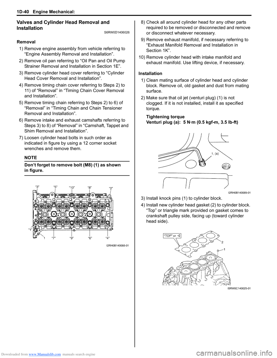
7) Loosen cylinder head bolts in such order as
indicated in figure by using a 12 corner socket
wrenches and remove them.
NOTE
Don’t forget to remove bolt (M8) (1) as shown
in figure.
8) Check all around cylinder head for any other parts
required to be removed or disconnected and remove
or disconnect whatever necessary.
9) Remove exhaust manifold, if necessary referring to
“Exhaust Manifold Removal and Installation in
Section 1K”.
10) Remove cylinder head with intake manifold and
exhaust manifold. Use lifting device, if necessary.
Installation
1) Clean mating surface of cylinder head and cylinder
block. Remove oil, old gasket and dust from mating
surface.
2) Make sure that oil jet (venturi plug) (1) is not
clogged. If it is not installed, install it as specified
torque.
Tightening torque
Venturi plug (a): 5 N·m (0.5 kgf-m, 3.5 lb-ft)
3) Install knock pins (1) to cylinder block.
4) Install new cylinder head gasket (2) to cylinder block.
“Top” or triangle mark provided on gasket comes to
crankshaft pulley side, facing up (toward cylinder
head side).
I2RH0B140088-01
I2RH0B140089-01
I5RW0C140025-01
Page 396 of 1556
Downloaded from www.Manualslib.com manuals search engine 1H-1 Ignition System:
Engine
Ignition System
General Description
Ignition System ConstructionS6RW0D1801001
The ignition system is an electronic (distributorless) ignition system. It consists of the parts as described below.
•ECM
It detects the engine and vehicle conditions through the signals from the sensors, determines the most suitable
ignition timing and time for electricity to flow to the primary coil and sends a signal to the ignitor (power unit) in the
ignition coil assembly.
•Ignition coil assembly (including an ignitor)
The ignition coil assembly has a built-in ignitor which turns ON and OFF the current flow to the primary coil
according to the signal from ECM. When the current flow to the primary coil is turned OFF, a high voltage is induced
in the secondary coil.
•High-tension cords and spark plugs
•CMP sensor (Camshaft position sensor) and CKP sensor (Crankshaft position sensor)
Using signals from these sensors, ECM identifies the specific cylinder whose piston is in the compression stroke,
detects the crank angle and adjusts initial ignition timing automatically.
•TP sensor, ECT sensor, MAP sensor, MAF sensor, IAT sensor, knock sensor and other sensors / switches
Although this ignition system does not have a distributor, it has two ignition coil assemblies (one is for No.1 and No.4
spark plugs and the other is for No.2 and No.3 spark plugs). When an ignition signal is sent from ECM to the ignitor in
the ignition coil assembly for No.1 and No.4 spark plugs, a high voltage is induced in the secondary coil and that
passes through the high-tension cords and causes No.1 and No.4 spark plugs to spark simultaneously. Likewise,
when an ignition signal is sent to the ignitor in the other ignition coil assembly, No.2 and No.3 spark plugs spark
simultaneously.
Page 437 of 1556
Downloaded from www.Manualslib.com manuals search engine Suspension General Diagnosis: 2A-3
Specifications
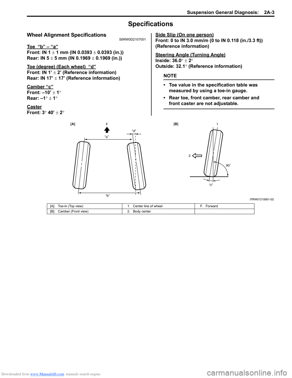
Wheel Alignment SpecificationsS6RW0D2107001
To e “b” – “a”
Front: IN 1 ± 1 mm (IN 0.0393 ± 0.0393 (in.))
Rear: IN 5 ± 5 mm (IN 0.1969 ± 0.1969 (in.))
Toe (degree) (Each wheel)
“d”
Front: IN 1’ ± 2’ (Reference information)
Rear: IN 17’ ± 17’ (Reference information)
Camber
“c”
Front: –10’ ± 1°
Rear: –1° ± 1°
Caster
Front: 3° 40’ ± 2°Side Slip (On one person)
Front: 0 to IN 3.0 mm/m (0 to IN 0.118 (in./3.3 ft))
(Reference information)
Steering Angle (Turning Angle)
Inside: 36.0° ± 2°
Outside: 32.1° (Reference information)
NOTE
• Toe value in the specification table was
measured by using a toe-in gauge.
• Rear toe, front camber, rear camber and
front caster are not adjustable.
“a”“d”
“b”F [A]
21
90
“c” [B]
I7RW01210001-02
[A]: Toe-in (Top view) 1. Center line of wheel F. Forward
[B]: Camber (Front view) 2. Body center