Coolant Circulation SUZUKI SX4 2006 1.G Service Workshop Manual
[x] Cancel search | Manufacturer: SUZUKI, Model Year: 2006, Model line: SX4, Model: SUZUKI SX4 2006 1.GPages: 1556, PDF Size: 37.31 MB
Page 24 of 1556
Downloaded from www.Manualslib.com manuals search engine 0A-1 General Information:
General Information
General Information
General Description
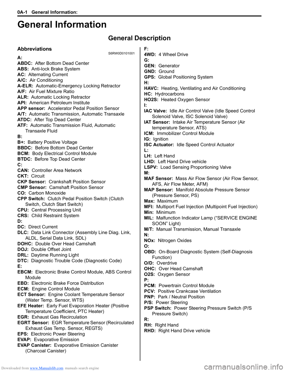
AbbreviationsS6RW0D0101001
A:
ABDC: After Bottom Dead Center
ABS: Anti-lock Brake System
AC: Alternating Current
A/C: Air Conditioning
A-ELR: Automatic-Emergency Locking Retractor
A/F: Air Fuel Mixture Ratio
ALR: Automatic Locking Retractor
API: American Petroleum Institute
APP sensor: Accelerator Pedal Position Sensor
A/T: Automatic Transmission, Automatic Transaxle
AT D C : After Top Dead Center
ATF: Automatic Transmission Fluid, Automatic
Transaxle Fluid
B:
B+: Battery Positive Voltage
BBDC: Before Bottom Dead Center
BCM: Body Electrical Control Module
BTDC: Before Top Dead Center
C:
CAN: Controller Area Network
CKT: Circuit
CKP Sensor: Crankshaft Position Sensor
CMP Sensor: Camshaft Position Sensor
CO: Carbon Monoxide
CPP Switch: Clutch Pedal Position Switch (Clutch
Switch, Clutch Start Switch)
CPU: Central Processing Unit
CRS: Child Restraint System
D:
DC: Direct Current
DLC: Data Link Connector (Assembly Line Diag. Link,
ALDL, Serial Data Link, SDL)
DOHC: Double Over Head Camshaft
DOJ: Double Offset Joint
DRL: Daytime Running Light
DTC: Diagnostic Trouble Code (Diagnostic Code)
E:
EBCM: Electronic Brake Control Module, ABS Control
Module
EBD: Electronic Brake Force Distribution
ECM: Engine Control Module
ECT Sensor: Engine Coolant Temperature Sensor
(Water Temp. Sensor, WTS)
EFE Heater: Early Fuel Evaporation Heater (Positive
Temperature Coefficient, PTC Heater)
EGR: Exhaust Gas Recirculation
EGRT Sensor: EGR Temperature Sensor (Recirculated
Exhaust Gas Temp. Sensor, REGTS)
EPS: Electronic Power Steering
EVAP: Evaporative Emission
EVAP Canister: Evaporative Emission Canister
(Charcoal Canister)F:
4WD: 4 Wheel Drive
G:
GEN: Generator
GND: Ground
GPS: Global Positioning System
H:
HAVC: Heating, Ventilating and Air Conditioning
HC: Hydrocarbons
HO2S: Heated Oxygen Sensor
I:
IAC Valve: Idle Air Control Valve (Idle Speed Control
Solenoid Valve, ISC Solenoid Valve)
IAT Sensor: Intake Air Temperature Sensor (Air
temperature Sensor, ATS)
ICM: Immobilizer Control Module
IG: Ignition
ISC Actuator: Idle Speed Control Actuator
L:
LH: Left Hand
LHD: Left Hand Drive vehicle
LSPV: Load Sensing Proportioning Valve
M:
MAF Sensor: Mass Air Flow Sensor (Air Flow Sensor,
AFS, Air Flow Meter, AFM)
MAP Sensor: Manifold Absolute Pressure Sensor
(Pressure Sensor, PS)
Max: Maximum
MFI: Multiport Fuel Injection (Multipoint Fuel Injection)
Min: Minimum
MIL: Malfunction Indicator Lamp (“SERVICE ENGINE
SOON” Light)
M/T: Manual Transmission, Manual Transaxle
N:
NOx: Nitrogen Oxides
O:
OBD: On-Board Diagnostic System (Self-Diagnosis
Function)
O/D: Overdrive
OHC: Over Head Camshaft
O2S: Oxygen Sensor
P:
PCM: Powertrain Control Module
PCV: Positive Crankcase Ventilation
PNP: Park / Neutral Position
P/S: Power Steering
PSP Switch: Power Steering Pressure Switch (P/S
Pressure Switch)
R:
RH: Right Hand
RHD: Right Hand Drive vehicle
Page 48 of 1556
Downloaded from www.Manualslib.com manuals search engine 1-iv Table of Contents
Crankshaft Inspection .......................................1D-63
Main Bearings Inspection ..................................1D-65
Sensor Plate Inspection ....................................1D-70
Rear Oil Seal Inspection ...................................1D-70
Flywheel Inspection...........................................1D-70
Cylinder Block Inspection ..................................1D-70
Specifications .....................................................1D-71
Tightening Torque Specifications ......................1D-71
Special Tools and Equipment ...........................1D-73
Recommended Service Material .......................1D-73
Special Tool ......................................................1D-73
Engine Lubrication System.....................1E-1
General Description ............................................. 1E-1
Engine Lubrication Description ........................... 1E-1
Diagnostic Information and Procedures ............ 1E-2
Oil Pressure Check ............................................. 1E-2
Repair Instructions .............................................. 1E-3
Oil Pan and Oil Pump Strainer Components....... 1E-3
Oil Pan and Oil Pump Strainer Removal and
Installation ......................................................... 1E-4
Oil Pan and Oil Pump Strainer Cleaning ............. 1E-5
Oil Pump Components ........................................ 1E-6
Oil Pump Removal and Installation ..................... 1E-6
Oil Pump Disassembly and Reassembly ............ 1E-6
Oil Pump Inspection ............................................ 1E-7
Specifications ....................................................... 1E-9
Tightening Torque Specifications ........................ 1E-9
Special Tools and Equipment ............................. 1E-9
Recommended Service Material ......................... 1E-9
Special Tool ........................................................ 1E-9
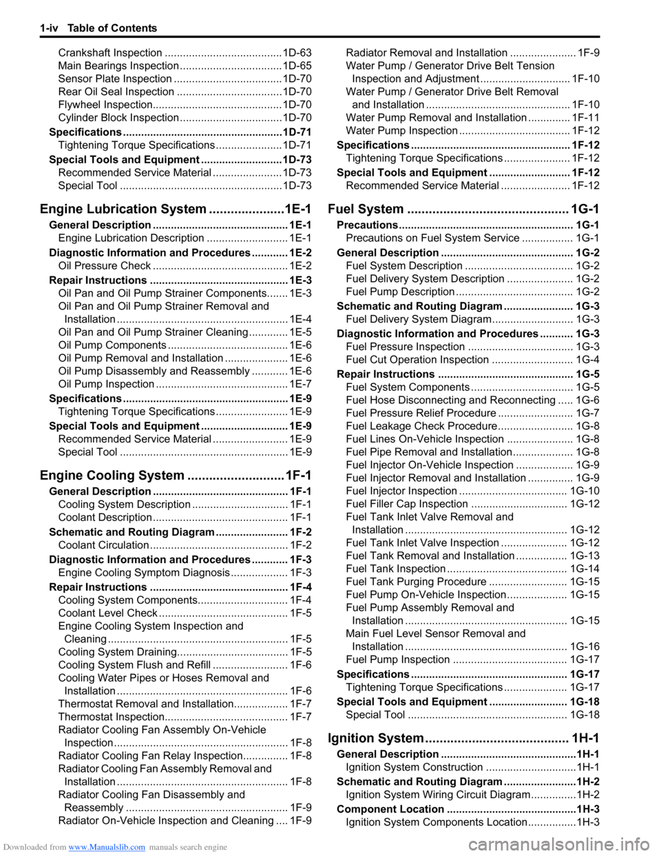
Engine Cooling System ........................... 1F-1
General Description ............................................. 1F-1
Cooling System Description ................................ 1F-1
Coolant Description ............................................. 1F-1
Schematic and Routing Diagram ........................ 1F-2
Coolant Circulation .............................................. 1F-2
Diagnostic Information and Procedures ............ 1F-3
Engine Cooling Symptom Diagnosis ................... 1F-3
Repair Instructions .............................................. 1F-4
Cooling System Components.............................. 1F-4
Coolant Level Check ........................................... 1F-5
Engine Cooling System Inspection and
Cleaning ............................................................ 1F-5
Cooling System Draining..................................... 1F-5
Cooling System Flush and Refill ......................... 1F-6
Cooling Water Pipes or Hoses Removal and
Installation ......................................................... 1F-6
Thermostat Removal and Installation.................. 1F-7
Thermostat Inspection......................................... 1F-7
Radiator Cooling Fan Assembly On-Vehicle
Inspection .......................................................... 1F-8
Radiator Cooling Fan Relay Inspection............... 1F-8
Radiator Cooling Fan Assembly Removal and
Installation ......................................................... 1F-8
Radiator Cooling Fan Disassembly and
Reassembly ...................................................... 1F-9
Radiator On-Vehicle Inspection and Cleaning .... 1F-9Radiator Removal and Installation ...................... 1F-9
Water Pump / Generator Drive Belt Tension
Inspection and Adjustment.............................. 1F-10
Water Pump / Generator Drive Belt Removal
and Installation ................................................ 1F-10
Water Pump Removal and Installation .............. 1F-11
Water Pump Inspection ..................................... 1F-12
Specifications ..................................................... 1F-12
Tightening Torque Specifications ...................... 1F-12
Special Tools and Equipment ........................... 1F-12
Recommended Service Material ....................... 1F-12
Fuel System ............................................. 1G-1
Precautions .......................................................... 1G-1
Precautions on Fuel System Service ................. 1G-1
General Description ............................................ 1G-2
Fuel System Description .................................... 1G-2
Fuel Delivery System Description ...................... 1G-2
Fuel Pump Description ....................................... 1G-2
Schematic and Routing Diagram ....................... 1G-3
Fuel Delivery System Diagram........................... 1G-3
Diagnostic Information and Procedures ........... 1G-3
Fuel Pressure Inspection ................................... 1G-3
Fuel Cut Operation Inspection ........................... 1G-4
Repair Instructions ............................................. 1G-5
Fuel System Components .................................. 1G-5
Fuel Hose Disconnecting and Reconnecting ..... 1G-6
Fuel Pressure Relief Procedure ......................... 1G-7
Fuel Leakage Check Procedure......................... 1G-8
Fuel Lines On-Vehicle Inspection ...................... 1G-8
Fuel Pipe Removal and Installation.................... 1G-8
Fuel Injector On-Vehicle Inspection ................... 1G-9
Fuel Injector Removal and Installation ............... 1G-9
Fuel Injector Inspection .................................... 1G-10
Fuel Filler Cap Inspection ................................ 1G-12
Fuel Tank Inlet Valve Removal and
Installation ...................................................... 1G-12
Fuel Tank Inlet Valve Inspection ...................... 1G-12
Fuel Tank Removal and Installation ................. 1G-13
Fuel Tank Inspection ........................................ 1G-14
Fuel Tank Purging Procedure .......................... 1G-15
Fuel Pump On-Vehicle Inspection.................... 1G-15
Fuel Pump Assembly Removal and
Installation ...................................................... 1G-15
Main Fuel Level Sensor Removal and
Installation ...................................................... 1G-16
Fuel Pump Inspection ...................................... 1G-17
Specifications .................................................... 1G-17
Tightening Torque Specifications ..................... 1G-17
Special Tools and Equipment .......................... 1G-18
Special Tool ..................................................... 1G-18
Ignition System ........................................ 1H-1
General Description .............................................1H-1
Ignition System Construction ..............................1H-1
Schematic and Routing Diagram ........................1H-2
Ignition System Wiring Circuit Diagram...............1H-2
Component Location ...........................................1H-3
Ignition System Components Location................1H-3
Page 83 of 1556
Downloaded from www.Manualslib.com manuals search engine Engine General Information and Diagnosis: 1A-33
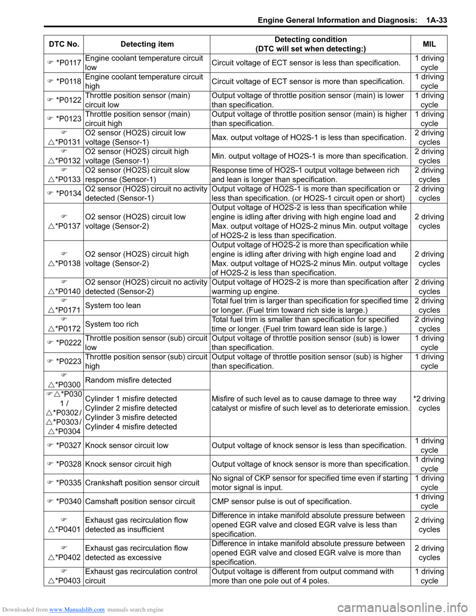
�) *P0117Engine coolant temperature circuit
lowCircuit voltage of ECT sensor is less than specification.1 driving
cycle
�) *P0118Engine coolant temperature circuit
highCircuit voltage of ECT sensor is more than specification.1 driving
cycle
�) *P0122Throttle position sensor (main)
circuit lowOutput voltage of throttle position sensor (main) is lower
than specification.1 driving
cycle
�) *P0123Throttle position sensor (main)
circuit highOutput voltage of throttle position sensor (main) is higher
than specification.1 driving
cycle
�)
�U*P0131O2 sensor (HO2S) circuit low
voltage (Sensor-1)Max. output voltage of HO2S-1 is less than specification.2 driving
cycles
�)
�U*P0132O2 sensor (HO2S) circuit high
voltage (Sensor-1)Min. output voltage of HO2S-1 is more than specification.2 driving
cycles
�)
�U*P0133O2 sensor (HO2S) circuit slow
response (Sensor-1)Response time of HO2S-1 output voltage between rich
and lean is longer than specification.2 driving
cycles
�) *P0134O2 sensor (HO2S) circuit no activity
detected (Sensor-1)Output voltage of HO2S-1 is more than specification or
less than specification. (or HO2S-1 circuit open or short)2 driving
cycles
�)
�U*P0137O2 sensor (HO2S) circuit low
voltage (Sensor-2)Output voltage of HO2S-2 is less than specification while
engine is idling after driving with high engine load and
Max. output voltage of HO2S-2 minus Min. output voltage
of HO2S-2 is less than specification.2 driving
cycles
�)
�U*P0138O2 sensor (HO2S) circuit high
voltage (Sensor-2)Output voltage of HO2S-2 is more than specification while
engine is idling after driving with high engine load and
Max. output voltage of HO2S-2 minus Min. output voltage
of HO2S-2 is less than specification.2 driving
cycles
�)
�U*P0140O2 sensor (HO2S) circuit no activity
detected (Sensor-2)Output voltage of HO2S-2 is more than specification after
warming up engine.
2 driving
cycles
�)
�U*P0171System too leanTotal fuel trim is larger than specification for specified time
or longer. (Fuel trim toward rich side is large.)2 driving
cycles
�)
�U*P0172System too richTotal fuel trim is smaller than specification for specified
time or longer. (Fuel trim toward lean side is large.)2 driving
cycles
�) *P0222Throttle position sensor (sub) circuit
lowOutput voltage of throttle position sensor (sub) is lower
than specification.1 driving
cycle
�) *P0223Throttle position sensor (sub) circuit
highOutput voltage of throttle position sensor (sub) is higher
than specification.1 driving
cycle
�)
�U*P0300Random misfire detected
Misfire of such level as to cause damage to three way
catalyst or misfire of such level as to deteriorate emission.*2 driving
cycles �)�U*P030
1 /
�U*P0302 /
�U*P0303 /
�U*P0304Cylinder 1 misfire detected
Cylinder 2 misfire detected
Cylinder 3 misfire detected
Cylinder 4 misfire detected
�) *P0327 Knock sensor circuit low Output voltage of knock sensor is less than specification.1 driving
cycle
�) *P0328 Knock sensor circuit high Output voltage of knock sensor is more than specification.1 driving
cycle
�) *P0335 Crankshaft position sensor circuitNo signal of CKP sensor for specified time even if starting
motor signal is input.1 driving
cycle
�) *P0340 Camshaft position sensor circuit CMP sensor pulse is out of specification.1 driving
cycle
�)
�U*P0401Exhaust gas recirculation flow
detected as insufficientDifference in intake manifold absolute pressure between
opened EGR valve and closed EGR valve is less than
specification.2 driving
cycles
�)
�U*P0402Exhaust gas recirculation flow
detected as excessive
Difference in intake manifold absolute pressure between
opened EGR valve and closed EGR valve is more than
specification.2 driving
cycles
�)
�U*P0403Exhaust gas recirculation control
circuitOutput voltage is different from output command with
more than one pole out of 4 poles.1 driving
cycle DTC No. Detecting itemDetecting condition
(DTC will set when detecting:)MIL
Page 287 of 1556
Downloaded from www.Manualslib.com manuals search engine Engine Mechanical: 1D-5
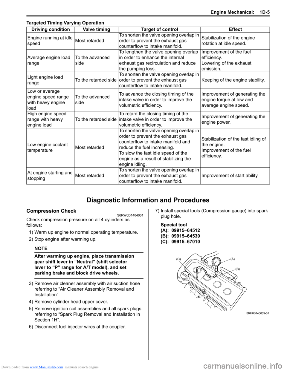
Targeted Timing Varying Operation
Diagnostic Information and Procedures
Compression CheckS6RW0D1404001
Check compression pressure on all 4 cylinders as
follows:
1) Warm up engine to normal operating temperature.
2) Stop engine after warming up.
NOTE
After warming up engine, place transmission
gear shift lever in “Neutral” (shift selector
lever to “P” range for A/T model), and set
parking brake and block drive wheels.
3) Remove air cleaner assembly with air suction hose
referring to “Air Cleaner Assembly Removal and
Installation”.
4) Remove cylinder head upper cover.
5) Remove ignition coil assemblies and all spark plugs
referring to “Spark Plug Removal and Installation in
Section 1H”.
6) Disconnect fuel injector wires at the coupler.7) Install special tools (Compression gauge) into spark
plug hole.
Special tool
(A): 09915–64512
(B): 09915–64530
(C): 09915–67010 Driving condition Valve timing Target of control Effect
Engine running at idle
speedMost retardedTo shorten the valve opening overlap in
order to prevent the exhaust gas
counterflow to intake manifold.Stabilization of the engine
rotation at idle speed.
Average engine load
rangeTo the advanced
sideTo lengthen the valve opening overlap
in order to enhance the internal
exhaust gas recirculation and reduce
the pumping loss.Improvement of the fuel
efficiency.
Lowering of the exhaust
emission.
Light engine load
rangeTo the retarded sideTo shorten the valve opening overlap in
order to prevent the exhaust gas
counterflow to intake manifold.Keeping of the engine stability.
Low or average
engine speed range
with heavy engine
loadTo the advanced
sideTo advance the closing timing of the
intake valve in order to improve the
volumetric efficiency.Improvement of generating the
engine torque at low and
average engine speed.
High engine speed
range with heavy
engine loadTo the retarded sideTo retard the closing timing of the
intake valve in order to improve the
volumetric efficiency.Improvement of generating the
engine power.
Low engine coolant
temperatureMost retardedTo shorten the valve opening overlap in
order to prevent the exhaust gas
counterflow to intake manifold and
reduce the fuel increasing.
To slow the fast idle speed of the
engine as a result of stabilizing the
engine idling.Stabilization of the fast idling of
the engine.
Improvement of the fuel
efficiency.
At engine starting and
stoppingMost retardedTo shorten the valve opening overlap in
order to prevent the exhaust gas
counterflow to intake manifold.Improvement of start ability.
(A)
(C)
(B)
I3RH0B140009-01
Page 367 of 1556
Downloaded from www.Manualslib.com manuals search engine Engine Cooling System: 1F-2
Schematic and Routing Diagram
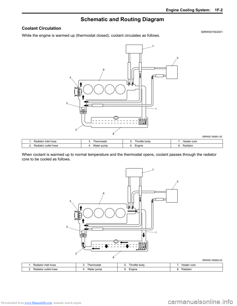
Coolant CirculationS6RW0D1602001
While the engine is warmed up (thermostat closed), coolant circulates as follows.
When coolant is warmed up to normal temperature and the thermostat opens, coolant passes through the radiator
core to be cooled as follows.
7
5
6
4
3
2
81
I5RW0C160001-02
1. Radiator inlet hose 3. Thermostat 5. Throttle body 7. Heater core
2. Radiator outlet hose 4. Water pump 6. Engine 8. Radiator
7
5
6
4
3
2
81
I5RW0C160002-02
1. Radiator inlet hose 3. Thermostat 5. Throttle body 7. Heater core
2. Radiator outlet hose 4. Water pump 6. Engine 8. Radiator
Page 980 of 1556
Downloaded from www.Manualslib.com manuals search engine 7B-40 Air Conditioning System: Automatic Type
HVAC Control DescriptionS6RW0D7221002
Temperature Control
HVAC control module calculates the target temperature
control door position based on signals from the
temperature selector, inside air temperature sensor,
outside air temperature sensor and sunload sensor and
controls the temperature control actuator so that the
current position of the temperature control door matches
its target position.
Fan Speed Control
HVAC control module calculates the target blower fan
speed based on signals from the temperature selector,
inside air temperature sensor, outside air temperature
sensor, ECT sensor and sunload sensor, compares it
with the current blower fan speed inputted from the
blower motor controller to control the current blower fan
speed to the target level.
Air Flow Outlet Control
HVAC control module calculates the target temperature
control door position based on signals from the
temperature selector, inside air temperature sensor,
outside air temperature sensor, ECT sensor and sunload
sensor. Using thus obtained target temperature control
door position, it further calculates the target air flow
control door position and controls the air flow control
actuator so that the current air flow control door position
becomes the target position.
Air Intake Position Control
HVAC control module determines the position of the air
intake control door based on signals from the
temperature selector, inside air temperature sensor,
outside air temperature sensor and sunload sensor and
selects any of the following positions by controlling the
position of the air intake control door.
• FRESH position (FRE)
• RECIRCULATION position (REC)
• MIX position (MIX)A/C Compressor Relay Control
HVAC control module outputs A/C switch ON signal to
ECM via BCM when the vehicle state satisfy conditions
described below.
• A/C switch is ON
• Evaporator temperature is higher than specified value
• Evaporator temperature sensor malfunction is not
detected
Communication of ECM and BCM is established by CAN
(Controller Area Network). (For more detail of CAN
communication, refer to “CAN Communication System
Description in Section 1A”).
ECM turns ON the A/C compressor relay when the
vehicle state satisfy conditions described below.
• A/C switch ON signal is inputted
• A/C refrigerant pressure is within specified range
• Engine speed is within specified range
• Engine coolant temperature is lower than specified
value
• Throttle opening is lower than specified value
• Vehicle is not in either state of starting or quick
acceleration
• ECT sensor malfunction is not detected
• A/C refrigerant pressure sensor malfunction is not
detected
Condenser Cooling Fan Relay Control
ECM turn ON the condenser cooling fan relay at the
same time when ECM turn ON the A/C compressor
relay.
Sub-Cool A/C System DescriptionS6RW0D7221003
Refer to “Sub-Cool A/C System Description”.
Page 996 of 1556
Downloaded from www.Manualslib.com manuals search engine 7B-56 Air Conditioning System: Automatic Type
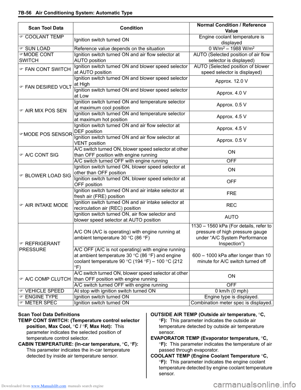
Scan Tool Data Definitions
TEMP CONT SWITCH: (Temperature control selector
position, Max Cool, °C / °F, Max Hot): This
parameter indicates the selected position of
temperature control selector.
CABIN TEMPERATURE: (In-car temperature, °C, °F):
This parameter indicates the in-car temperature
detected by inside air temperature sensor.OUTSIDE AIR TEMP (Outside air temperature, °C,
°F): This parameter indicates the outside air
temperature detected by outside air temperature
sensor.
EVAPORATOR TEMP (Evaporator temperature, °C,
°F): This parameter indicates the temperature of air
passed through evaporator.
COOLANT TEMP (Engine Coolant Temperature °C,
°F): This parameter indicates the engine coolant
temperature detected by engine coolant temperature
sensor. �) COOLANT TEMP
Ignition switch turned ONEngine coolant temperature is
displayed
�) SUN LOAD Reference value depends on the situation 0 W/m
2 – 1988 W/m2
�)MODE CONT
SWITCHIgnition switch turned ON and air flow selector at
AUTO positionAUTO (Selected position of air flow
selector is displayed)
�) FAN CONT SWITCHIgnition switch turned ON and blower speed selector
at AUTO positionAUTO (Selected position of blower
speed selector is displayed)
�) FAN DESIRED VOLTIgnition switch turned ON and blower speed selector
at HighApprox. 12.0 V
Ignition switch turned ON and blower speed selector
at LowApprox. 4.0 V
�) AIR MIX POS SENIgnition switch turned ON and temperature selector
at maximum cool positionApprox. 0.5 V
Ignition switch turned ON and temperature selector
at maximum hot positionApprox. 4.5 V
�)MODE POS SENSORIgnition switch turned ON and air flow selector at
DEF positionApprox. 4.5 V
Ignition switch turned ON and air flow selector at
VENT positionApprox. 0.5 V
�) A/C CONT SIGA/C switch turned ON, blower speed selector at other
than OFF position with engine runningON
A/C switch turned OFF with engine running OFF
�) BLOWER LOAD SIGIgnition switch turned ON, blower speed selector at
other than OFF positionON
Ignition switch turned ON, blower speed selector at
OFF positionOFF
�) AIR INTAKE MODEIgnition switch turned ON and air intake selector at
fresh air (FRE) positionFRE
Ignition switch turned ON and air intake selector at
recirculation air (REC) positionREC
Ignition switch turned ON, air flow selector and
blower speed selector at AUTO positionAUTO
�) REFRIGERANT
PRESSUREA/C ON (A/C is operating) with engine running at
ambient temperature 30 °C (86 °F)1130 – 1560 kPa (For details, refer to
pressure of high pressure gauge
under “A/C System Performance
Inspection”)
A/C OFF (A/C is not operating) with engine running
at ambient temperature 30 °C (86 °F) and engine
coolant temperature 90 °C (194 °F) – 100 °C (212
°F)600 – 1000 kPa after longer than 10
minute for A/C switch turned off
�) A/C COMP CLUTCHA/C switch turned ON, blower speed selector at other
than OFF position with engine runningON
A/C switch turned OFF with engine running OFF
�) VEHICLE SPEED At stop with ignition switch turned ON 0 km/h (0 mph)
�) ENGINE TYPE Ignition switch turned ON Engine type is displayed.
�) METER SPEC Ignition switch turned ONCombination meter spec is displayed. Scan Tool Data ConditionNormal Condition / Reference
Va l u e