SUZUKI SX4 2010 1.G Owner's Guide
Manufacturer: SUZUKI, Model Year: 2010, Model line: SX4, Model: SUZUKI SX4 2010 1.GPages: 297, PDF Size: 4.51 MB
Page 31 of 297
2-14
BEFORE DRIVING
80J23-03E
The turn signal lights will flash once when
the doors are locked.
When the doors are unlocked:
The turn signal lights will flash twice.
If the interior light switch is in the
“DOOR” position, the interior light will
turn on for about 15 seconds and then
fade out. If you insert the key into the
ignition switch during this time, the light
will start to fade out immediately.
Be sure the doors are locked after you
operate the “LOCK” button (1).
If no door is opened within about 30 sec-
onds after the “UNLOCK” button (2) is
operated, the doors will automatically lock
again.
NOTE:
The maximum operating distance of the
keyless entry system transmitter is about
5 m (16 ft.), but this can vary depending
on the surroundings, especially near
other transmitting devices such as radio
towers or CB (Citizen’s Band) radios.
The door locks cannot be operated with
the transmitter, if the ignition key is
inserted in the ignition switch.
If you lose one of the transmitters, ask
your SUZUKI dealer as soon as possible
for a replacement. Be sure to have your
dealer program the new transmitter code
in your vehicle’s memory so that the old
code is erased, or perform the program-
ming procedure yourself according to the
instructions in this section.“PANIC” button (3) function
This function is to get the attention of oth-
ers.
Press the “PANIC” button (3) for more than
1 second. The headlights and taillights will
blink for about 30 seconds. Also, the horn
will sound intermittently for about 30 sec-
onds at the same time.
To cancel the “PANIC” mode, press any
button (PANIC, LOCK or UNLOCK) on the
transmitter. You can also insert the key in
the ignition switch and turn to the “ON”
position to cancel the “PANIC” mode.
NOTE:
The “PANIC” button function will not acti-
vate when the key is in the ignition switch.Replacement of the battery
If the transmitter becomes unreliable,
replace the battery.
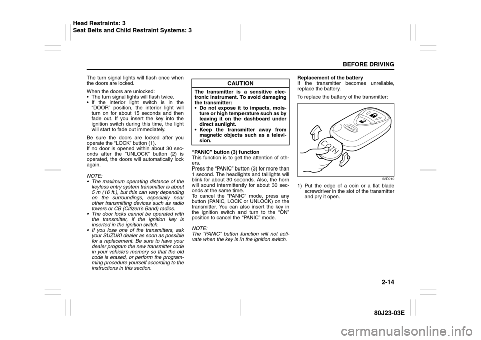
To replace the battery of the transmitter:
52D210
1) Put the edge of a coin or a flat blade
screwdriver in the slot of the transmitter
and pry it open.
CAUTION
The transmitter is a sensitive elec-
tronic instrument. To avoid damaging
the transmitter:
Do not expose it to impacts, mois-
ture or high temperature such as by
leaving it on the dashboard under
direct sunlight.
Keep the transmitter away from
magnetic objects such as a televi-
sion.
Head Restraints: 3
Seat Belts and Child Restraint Systems: 3
Page 32 of 297
2-15BEFORE DRIVING
80J23-03E
80J2077
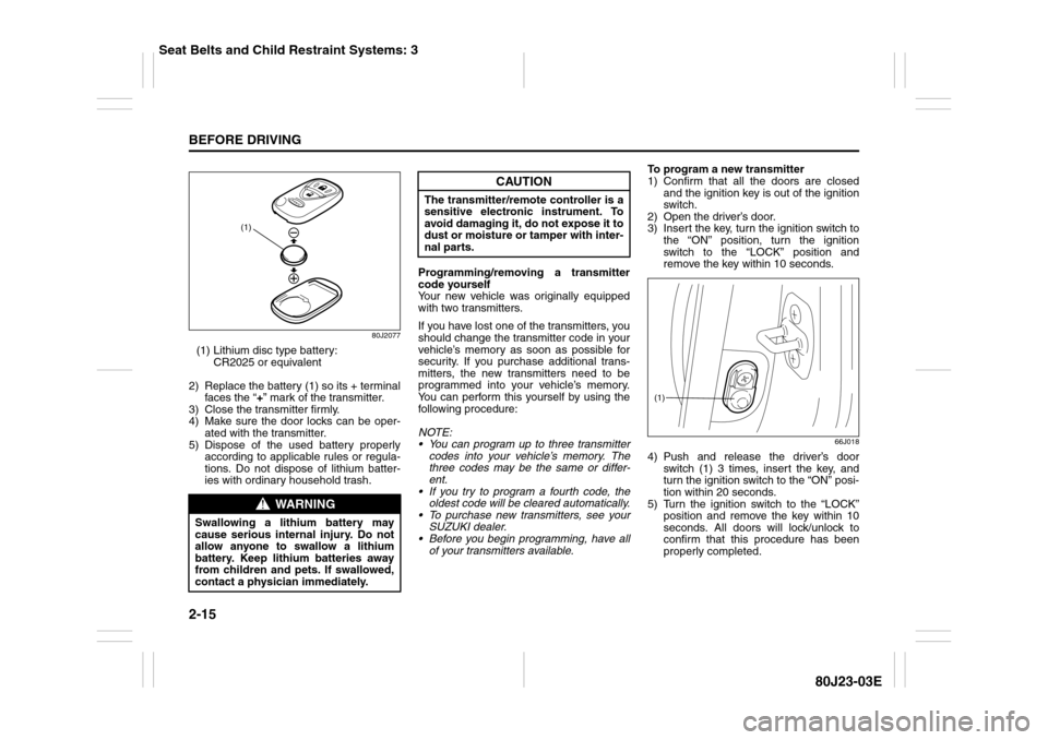
(1) Lithium disc type battery:
CR2025 or equivalent
2) Replace the battery (1) so its + terminal
faces the “+” mark of the transmitter.
3) Close the transmitter firmly.
4) Make sure the door locks can be oper-
ated with the transmitter.
5) Dispose of the used battery properly
according to applicable rules or regula-
tions. Do not dispose of lithium batter-
ies with ordinary household trash.Programming/removing a transmitter
code yourself
Your new vehicle was originally equipped
with two transmitters.
If you have lost one of the transmitters, you
should change the transmitter code in your
vehicle’s memory as soon as possible for
security. If you purchase additional trans-
mitters, the new transmitters need to be
programmed into your vehicle’s memory.
You can perform this yourself by using the
following procedure:
NOTE:
You can program up to three transmitter
codes into your vehicle’s memory. The
three codes may be the same or differ-
ent.
If you try to program a fourth code, the
oldest code will be cleared automatically.
To purchase new transmitters, see your
SUZUKI dealer.
Before you begin programming, have all
of your transmitters available.To program a new transmitter
1) Confirm that all the doors are closed
and the ignition key is out of the ignition
switch.
2) Open the driver’s door.
3) Insert the key, turn the ignition switch to
the “ON” position, turn the ignition
switch to the “LOCK” position and
remove the key within 10 seconds.
66J018
4) Push and release the driver’s door
switch (1) 3 times, insert the key, and
turn the ignition switch to the “ON” posi-
tion within 20 seconds.
5) Turn the ignition switch to the “LOCK”
position and remove the key within 10
seconds. All doors will lock/unlock to
confirm that this procedure has been
properly completed.
WARNING
Swallowing a lithium battery may
cause serious internal injury. Do not
allow anyone to swallow a lithium
battery. Keep lithium batteries away
from children and pets. If swallowed,
contact a physician immediately.
(1)
CAUTION
The transmitter/remote controller is a
sensitive electronic instrument. To
avoid damaging it, do not expose it to
dust or moisture or tamper with inter-
nal parts.
(1)
Seat Belts and Child Restraint Systems: 3
Page 33 of 297
2-16
BEFORE DRIVING
80J23-03E
52D212
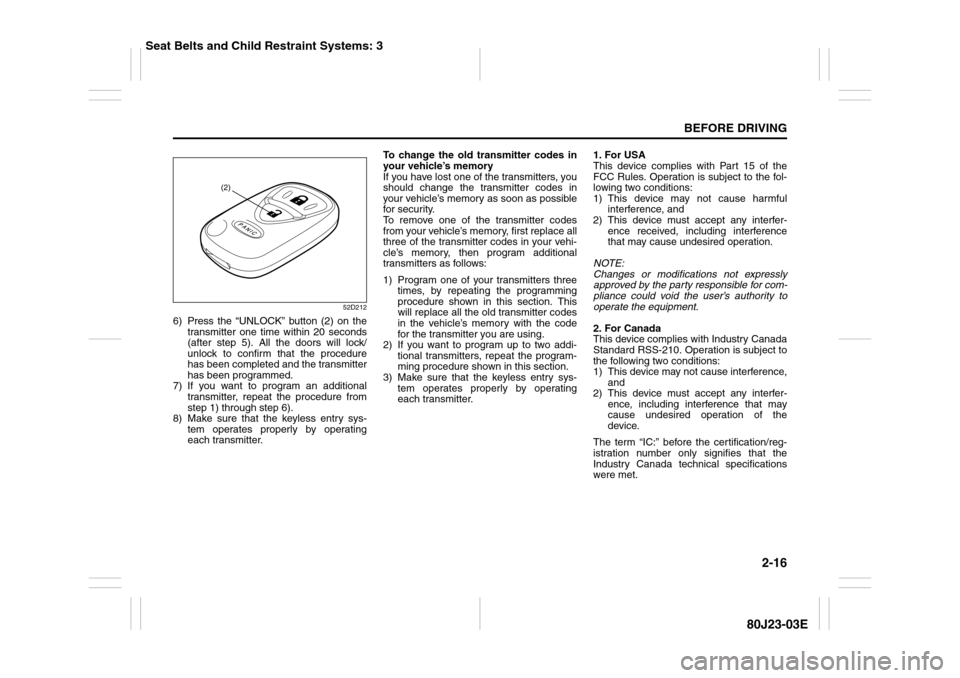
6) Press the “UNLOCK” button (2) on the
transmitter one time within 20 seconds
(after step 5). All the doors will lock/
unlock to confirm that the procedure
has been completed and the transmitter
has been programmed.
7) If you want to program an additional
transmitter, repeat the procedure from
step 1) through step 6).
8) Make sure that the keyless entry sys-
tem operates properly by operating
each transmitter.To change the old transmitter codes in
your vehicle’s memory
If you have lost one of the transmitters, you
should change the transmitter codes in
your vehicle’s memory as soon as possible
for security.
To remove one of the transmitter codes
from your vehicle’s memory, first replace all
three of the transmitter codes in your vehi-
cle’s memory, then program additional
transmitters as follows:
1) Program one of your transmitters three
times, by repeating the programming
procedure shown in this section. This
will replace all the old transmitter codes
in the vehicle’s memory with the code
for the transmitter you are using.
2) If you want to program up to two addi-
tional transmitters, repeat the program-
ming procedure shown in this section.
3) Make sure that the keyless entry sys-
tem operates properly by operating
each transmitter.1. For USA
This device complies with Part 15 of the
FCC Rules. Operation is subject to the fol-
lowing two conditions:
1) This device may not cause harmful
interference, and
2) This device must accept any interfer-
ence received, including interference
that may cause undesired operation.
NOTE:
Changes or modifications not expressly
approved by the party responsible for com-
pliance could void the user’s authority to
operate the equipment.
2. For Canada
This device complies with Industry Canada
Standard RSS-210. Operation is subject to
the following two conditions:
1) This device may not cause interference,
and
2) This device must accept any interfer-
ence, including interference that may
cause undesired operation of the
device.
The term “IC:” before the certification/reg-
istration number only signifies that the
Industry Canada technical specifications
were met.
(2)
Seat Belts and Child Restraint Systems: 3
Page 34 of 297
2-17BEFORE DRIVING
80J23-03E
Theft Deterrent Light
80JM022
This light will blink with the ignition switch
in the “OFF” or “ACC” position. The blink-
ing light is intended to deter theft by lead-
ing others to believe that the vehicle is
equipped with a security system.
WindowsPower Window ControlsDriver’s side
80JC095
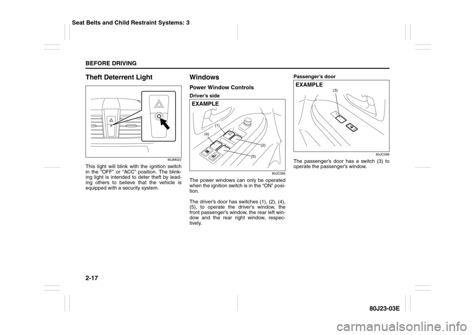
The power windows can only be operated
when the ignition switch is in the “ON” posi-
tion.
The driver’s door has switches (1), (2), (4),
(5), to operate the driver’s window, the
front passenger’s window, the rear left win-
dow and the rear right window, respec-
tively.Passenger’s door
80JC096
The passenger’s door has a switch (3) to
operate the passenger’s window.
(1)
(2)
(4)
(5)
EXAMPLE
(3)
EXAMPLE
Seat Belts and Child Restraint Systems: 3
Page 35 of 297
2-18
BEFORE DRIVING
80J23-03E
81A009
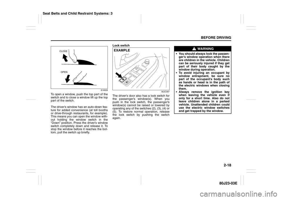
To open a window, push the top part of the
switch and to close a window lift up the top
part of the switch.
The driver’s window has an auto-down fea-
ture for added convenience (at toll booths
or drive-through restaurants, for example).
This means you can open the window with-
out holding the window switch in the
“Down” position. Press the driver’s window
switch completely down and release it. To
stop the window before it reaches the bot-
tom, pull the switch up briefly.Lock switch
80JC097
The driver’s door also has a lock switch for
the passenger’s window(s). When you
push in the lock switch, the passenger’s
window(s) cannot be raised or lowered by
operating any of the switches (2), (3), (4) or
(5). To restore normal operation, release
the lock switch by pushing the switch
again.
CLOSE
OPEN
EXAMPLE
WARNING
You should always lock the passen-
ger’s window operation when there
are children in the vehicle. Children
can be seriously injured if they get
part of their body caught by the
window during operation.
To avoid injuring an occupant by
window entrapment, be sure no
part of the occupant’s body such
as hands or head is in the path of
the electric windows when closing
them.
Always remove the ignition key
when leaving the vehicle even if
only for a short time. Also do not
leave children alone in a parked
vehicle. Unattended children could
use the electric window switches
and get trapped by the window.
Seat Belts and Child Restraint Systems: 3
Page 36 of 297
2-19BEFORE DRIVING
80J23-03E
52LM012
NOTE:
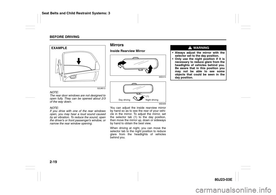
The rear door windows are not designed to
open fully. They can be opened about 2/3
of the way down.
NOTE:
If you drive with one of the rear windows
open, you may hear a loud sound caused
by air vibration. To reduce the sound, open
the driver’s or front passenger’s window, or
narrow the rear window opening.
MirrorsInside Rearview Mirror
65D410
65D409
You can adjust the inside rearview mirror
by hand so as to see the rear of your vehi-
cle in the mirror. To adjust the mirror, set
the selector tab (1) to the day position,
then move the mirror up, down or sideways
by hand to obtain the best view.
When driving at night, you can move the
selector tab to the night position to reduce
glare from the headlights of vehicles
behind you.
EXAMPLE
(1)
Day driving Night driving
WARNING
Always adjust the mirror with the
selector set to the day position.
Only use the night position if it is
necessary to reduce glare from the
headlights of vehicles behind you.
Be aware that in this position you
may not be able to see some
objects that could be seen in the
day position.
Seat Belts and Child Restraint Systems: 3
Page 37 of 297
2-20
BEFORE DRIVING
80J23-03E
Outside Rearview Mirrors
79J033
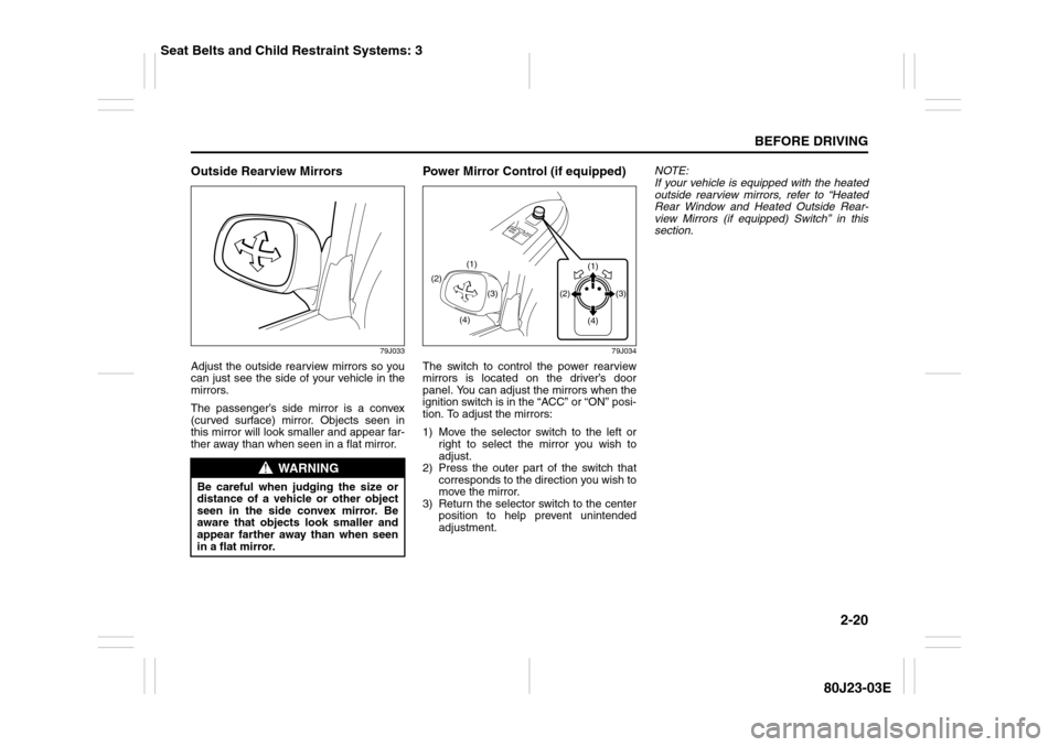
Adjust the outside rearview mirrors so you
can just see the side of your vehicle in the
mirrors.
The passenger’s side mirror is a convex
(curved surface) mirror. Objects seen in
this mirror will look smaller and appear far-
ther away than when seen in a flat mirror.
Power Mirror Control (if equipped)
79J034
The switch to control the power rearview
mirrors is located on the driver’s door
panel. You can adjust the mirrors when the
ignition switch is in the “ACC” or “ON” posi-
tion. To adjust the mirrors:
1) Move the selector switch to the left or
right to select the mirror you wish to
adjust.
2) Press the outer part of the switch that
corresponds to the direction you wish to
move the mirror.
3) Return the selector switch to the center
position to help prevent unintended
adjustment.NOTE:
If your vehicle is equipped with the heated
outside rearview mirrors, refer to “Heated
Rear Window and Heated Outside Rear-
view Mirrors (if equipped) Switch” in this
section.
WARNING
Be careful when judging the size or
distance of a vehicle or other object
seen in the side convex mirror. Be
aware that objects look smaller and
appear farther away than when seen
in a flat mirror.
(2)
(4)(3) (1)
(1)
(3) (2)
(4)
Seat Belts and Child Restraint Systems: 3
Page 38 of 297
2-21BEFORE DRIVING
80J23-03E
Front SeatsSeat AdjustmentAdjusting Seat Position
80JM023
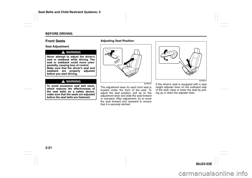
The adjustment lever for each front seat is
located under the front of the seat. To
adjust the seat position, pull up on the
adjustment lever and slide the seat forward
or rearward. After adjustment, try to move
the seat forward and rearward to ensure
that it is securely latched.
80JM024
If the driver’s seat is equipped with a seat
height adjuster lever on the outboard side
of the seat, raise or lower the seat by pull-
ing up or down the adjuster lever.
WARNING
Never attempt to adjust the driver’s
seat or seatback while driving. The
seat or seatback could move unex-
pectedly, causing loss of control.
Make sure that the driver’s seat and
seatback are properly adjusted
before you start driving.
WARNING
To avoid excessive seat belt slack,
which reduces the effectiveness of
the seat belts as a safety device,
make sure that the seats are adjusted
before the seat belts are fastened.
Seat Belts and Child Restraint Systems: 3
Page 39 of 297
2-22
BEFORE DRIVING
80J23-03E
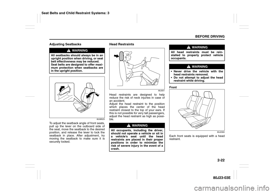
Adjusting Seatbacks
80JM025
To adjust the seatback angle of front seats,
pull up the lever on the outboard side of
the seat, move the seatback to the desired
position, and release the lever to lock the
seatback in place. After adjustment, try
moving the seatback to make sure it is
securely locked.
Head Restraints
80J001
Head restraints are designed to help
reduce the risk of neck injuries in case of
an accident.
Adjust the head restraint to the position
which places the center of the head
restraint closest to the top of your ears. If
this is not possible for very tall passengers,
adjust the head restraint as high as possi-
ble.Front
80J2060
Each front seats is equipped with a head
restraint.
WARNING
All seatbacks should always be in an
upright position when driving, or seat
belt effectiveness may be reduced.
Seat belts are designed to offer maxi-
mum protection when seatbacks are
in the upright position.
WARNING
All occupants, including the driver,
should not operate a vehicle or sit in
a vehicle’s seat until the head
restraints are placed in their proper
positions in order to minimize the
risk of severe injury in the event of a
crash.
WARNING
All head restraints must be rein-
stalled to properly protect vehicle
occupants.
WARNING
Never drive the vehicle with the
head restraints removed.
Do not attempt to adjust the head
restraint while driving.
Seat Belts and Child Restraint Systems: 3
Page 40 of 297
2-23BEFORE DRIVING
80J23-03E
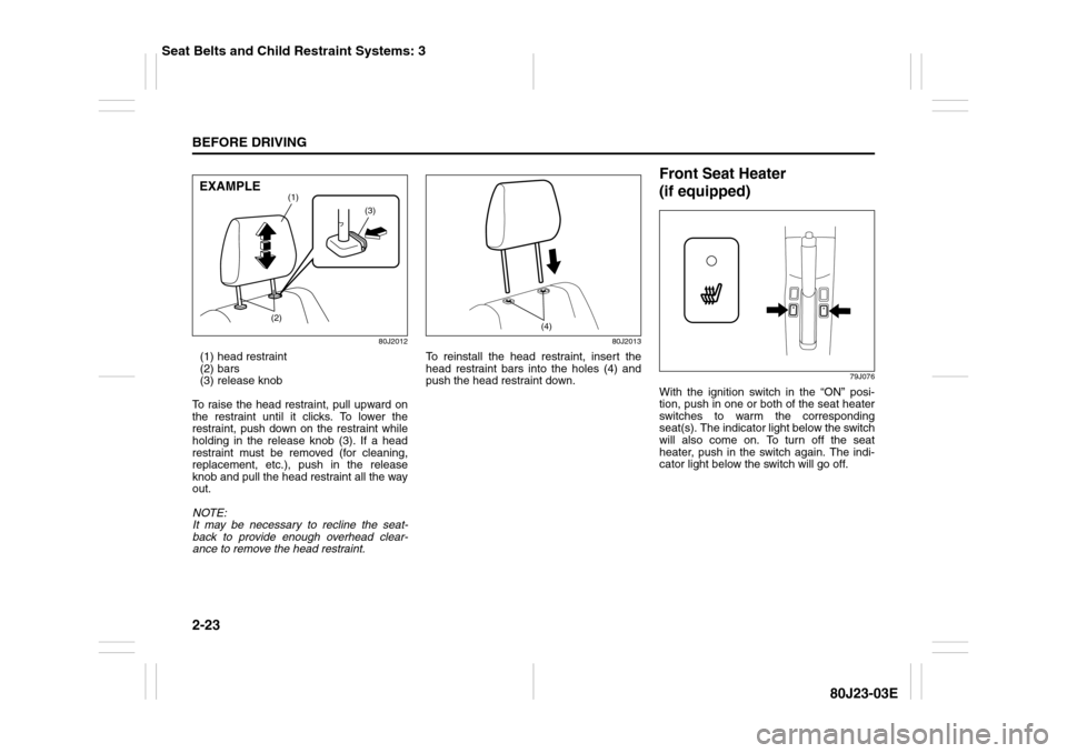
80J2012
(1) head restraint
(2) bars
(3) release knob
To raise the head restraint, pull upward on
the restraint until it clicks. To lower the
restraint, push down on the restraint while
holding in the release knob (3). If a head
restraint must be removed (for cleaning,
replacement, etc.), push in the release
knob and pull the head restraint all the way
out.
NOTE:
It may be necessary to recline the seat-
back to provide enough overhead clear-
ance to remove the head restraint.
80J2013
To reinstall the head restraint, insert the
head restraint bars into the holes (4) and
push the head restraint down.
Front Seat Heater
(if equipped)
79J076
With the ignition switch in the “ON” posi-
tion, push in one or both of the seat heater
switches to warm the corresponding
seat(s). The indicator light below the switch
will also come on. To turn off the seat
heater, push in the switch again. The indi-
cator light below the switch will go off.
(3)
(1)
(2)
EXAMPLE
(4)
Seat Belts and Child Restraint Systems: 3