battery TATA SAFARI 2015 Owners Manual
[x] Cancel search | Manufacturer: TATA, Model Year: 2015, Model line: SAFARI, Model: TATA SAFARI 2015Pages: 161, PDF Size: 2.55 MB
Page 44 of 161
44
INDICATORS AND INSTRUMENTSINDIC INDICINDIC INDIC
INDIC
A AA A
A
T TT T
T
ORS ORSORS ORS
ORS
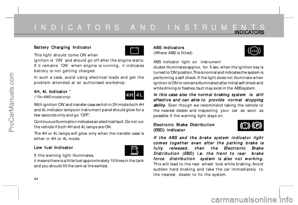
ABS Indicators ABS IndicatorsABS Indicators ABS Indicators
ABS Indicators
( Where ABS is fitted)
ABS indicator light on instrument
cluster illuminates approx. for 5 sec. when the ignition key is
turned to ‘ON’ position. This is normal and indicates the system is
performing a self check. If the light does not illuminate when
ignition is ‘ON’ or remains illuminated after initial self check and
while driving or flashes, fault may exist in the ABS system.
In this case also the normal braking system is still In this case also the normal braking system is stillIn this case also the normal braking system is still In this case also the normal braking system is still
In this case also the normal braking system is still
effective and can able to provide normal stopping effective and can able to provide normal stoppingeffective and can able to provide normal stopping effective and can able to provide normal stopping
effective and can able to provide normal stopping
abilit abilitabilit abilit
abilit
y yy y
y
.. ..
.
Even though we recommend taking the vehicle to
the nearest dealer and inspecting your car as soon as
possible if the warning light stays on.
Electronic Brake Distribution Electronic Brake DistributionElectronic Brake Distribution Electronic Brake Distribution
Electronic Brake Distribution
(EBD) indicator (EBD) indicator(EBD) indicator (EBD) indicator
(EBD) indicator
If the ABS and the brake system indicator light If the ABS and the brake system indicator lightIf the ABS and the brake system indicator light If the ABS and the brake system indicator light
If the ABS and the brake system indicator light
comes together even after the parking brake is comes together even after the parking brake iscomes together even after the parking brake is comes together even after the parking brake is
comes together even after the parking brake is
fully released, then the Electronic Brake fully released, then the Electronic Brakefully released, then the Electronic Brake fully released, then the Electronic Brake
fully released, then the Electronic Brake
Distribution (EBD) i.e. the front to rear brake Distribution (EBD) i.e. the front to rear brakeDistribution (EBD) i.e. the front to rear brake Distribution (EBD) i.e. the front to rear brake
Distribution (EBD) i.e. the front to rear brake
force distribution system is also not working. force distribution system is also not working.force distribution system is also not working. force distribution system is also not working.
force distribution system is also not working.
This will lead to the rear wheel lock while braking. Avoid
sudden hard braking and take the car immediately to
the nearest dealer to fix the system.
ABS ABSABS ABS
ABSBattery Charging Indicator Battery Charging IndicatorBattery Charging Indicator Battery Charging Indicator
Battery Charging Indicator
This light should come ON when
ignition is ‘ON’ and should go off after the engine starts.
If it remains ‘ON’ when engine is running, it indicates
battery is not getting charged.
In such a case, avoid using electrical loads and get the
problem attended at an authorised workshop.
4H, 4L Indicator 4H, 4L Indicator 4H, 4L Indicator 4H, 4L Indicator
4H, 4L Indicator *
(* For 4WD model only)
With ignition ‘ON’ and transfer case switch in 2H mode both 4H
and 4L indicator lamps on instrument panel should glow for a
few seconds only and go ‘OFF’.
Continuous illumination indicates an electrical fault. Do not run
the vehicle if both 4H and 4L lamps are ON.
The 4H or 4L lamps will glow only when the transfer case is
either in 4H or 4L mode.
Low fuel Indicator Low fuel IndicatorLow fuel Indicator Low fuel Indicator
Low fuel Indicator
If this warning light illuminates,
it means there is a little fuel approximately 10 litres in the tank
and you should fill the tank at the earliest.
ProCarManuals.com
Page 61 of 161
61
C CC C
C
igar igarigar igar
igar
ett ettett ett
ett
e Ligh e Lighe Ligh e Ligh
e Ligh
t tt t
t
er and A er and Aer and A er and A
er and A
sh sh sh sh
sh
T TT T
T
r rr r
r
a aa a
a
y (R y (Ry (R y (R
y (R
ear) ear)ear) ear)
ear)
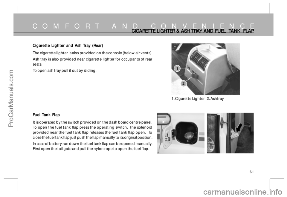
The cigarette lighter is also provided on the console (below air vents).
Ash tray is also provided near cigarette lighter for occupants of rear
seats.
To open ash tray pull it out by sliding.
F FF F
F
uel uel uel uel
uel
T TT T
T
ank F ank Fank F ank F
ank F
lap laplap lap
lap
It is operated by the switch provided on the dash board centre panel.
To open the fuel tank flap press the operating switch. The solenoid
provided near the fuel tank flap releases the fuel tank flap open. To
close the fuel tank flap just push the flap manually to its original position.
In case of battery run down the fuel tank flap can be opened manually.
First open the tail gate and pull the nylon rope to open the fuel flap.
COMFORT AND CONVENIENCE
2
1
1. Cigarette Lighter 2. Ashtray
CIGARET CIGARET CIGARET CIGARET
CIGARET
TE LIGHTER & ASH TE LIGHTER & ASH TE LIGHTER & ASH TE LIGHTER & ASH
TE LIGHTER & ASH
TR TRTR TR
TR
A AA A
A
Y AND FUEL Y AND FUEL Y AND FUEL Y AND FUEL
Y AND FUEL
T TT T
T
ANK FL ANK FLANK FL ANK FL
ANK FL
AP APAP AP
AP
ProCarManuals.com
Page 100 of 161
100
Parking Brake :Lever type, Console
mounted, Cable
operated mechanical
linkages acting on rear
wheels.
9.0 9.09.0 9.0
9.0
FRAME : FRAME :FRAME : FRAME :
FRAME :
Frame :Ladder type cranked frame
with boxed section long
members and welded cross
members
Depth :110 mm (max.)
Width :60mm
10.0 10.010.0 10.0
10.0
SUSPENSION : SUSPENSION :SUSPENSION : SUSPENSION :
SUSPENSION :
Front :Double wishbone type
with Torsion bar springs.
Rear :Coil spring type 5 link
suspension
Shock Absorber : Hydraulic double acting
telescopic type at front
and rear.
Antiroll bar : At both front & rear.
FR FR FR FR
FR
AME AMEAME AME
AME
,, ,,
,
SUSPENSION, SUSPENSION, SUSPENSION, SUSPENSION,
SUSPENSION,
WHEELS & WHEELS & WHEELS & WHEELS &
WHEELS &
T TT T
T
YRES, YRES,YRES, YRES,
YRES,
FUEL FUEL FUEL FUEL
FUEL
T TT T
T
ANK , ANK ,ANK , ANK ,
ANK ,
BOD BOD BOD BOD
BOD
Y AND ELECTRIC Y AND ELECTRICY AND ELECTRIC Y AND ELECTRIC
Y AND ELECTRIC
AL SY AL SYAL SY AL SY
AL SY
STEM STEMSTEM STEM
STEM
11.0 11.011.0 11.0
11.0
WHEELS & WHEELS & WHEELS & WHEELS &
WHEELS &
T TT T
T
YRES : YRES :YRES : YRES :
YRES :
Tyres : 235/70 R 16
Radial with tube
Wheels rims : 6.5 J x 16 Steel rims
No. of wheels : Front 2, Rear 2, Spare -1
12.0 12.012.0 12.0
12.0
FUEL FUEL FUEL FUEL
FUEL
T TT T
T
ANK : ANK :ANK : ANK :
ANK :
Capacity :65 Litres
13.0 13.013.0 13.0
13.0
BODY : BODY :BODY : BODY :
BODY :
Type : Normal control all steel
shell with five doors.
14.0 14.014.0 14.0
14.0
ELECTRICAL SYSTEM : ELECTRICAL SYSTEM :ELECTRICAL SYSTEM : ELECTRICAL SYSTEM :
ELECTRICAL SYSTEM :
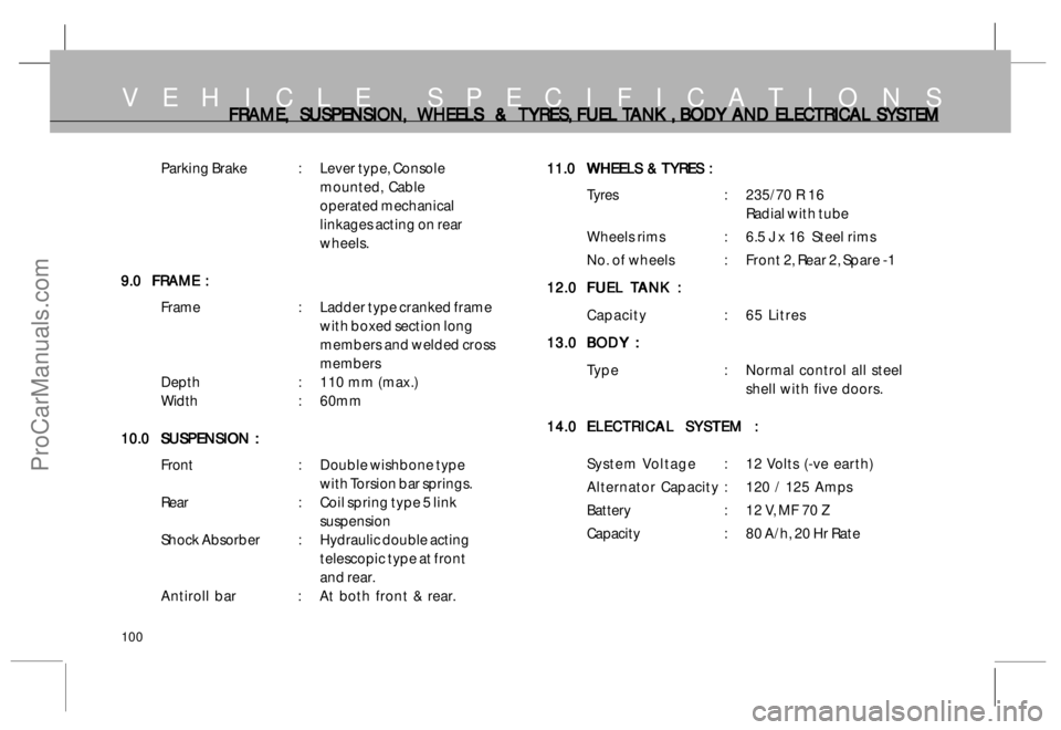
System Voltage : 12 Volts (-ve earth)
Alternator Capacity :120 / 125 Amps
Battery : 12 V, MF 70 Z
Capacity : 80 A/h, 20 Hr Rate
VEHICLE SPECIFICATIONS
ProCarManuals.com
Page 103 of 161
103
MAINTENANCE
• •• •
•Engine Compartment Engine CompartmentEngine Compartment Engine Compartment
Engine Compartment
• •• •
•Air filter Air filterAir filter Air filter
Air filter
• •• •
•Cooling system Cooling systemCooling system Cooling system
Cooling system
• •• •
•Engine oil & oil filter Engine oil & oil filterEngine oil & oil filter Engine oil & oil filter
Engine oil & oil filter
• •• •
•Changing fuel filter Changing fuel filterChanging fuel filter Changing fuel filter
Changing fuel filter
• •• •
•Changing gear box oil Changing gear box oilChanging gear box oil Changing gear box oil
Changing gear box oil
• •• •
•Changing transfer case oil Changing transfer case oilChanging transfer case oil Changing transfer case oil
Changing transfer case oil
• •• •
•Changing front axle & rear axle oil Changing front axle & rear axle oilChanging front axle & rear axle oil Changing front axle & rear axle oil
Changing front axle & rear axle oil
• •• •
•Head lamp & head lamp focus adjustment Head lamp & head lamp focus adjustmentHead lamp & head lamp focus adjustment Head lamp & head lamp focus adjustment
Head lamp & head lamp focus adjustment
• •• •
•Clutch & brake fluid Clutch & brake fluidClutch & brake fluid Clutch & brake fluid
Clutch & brake fluid
• •• •
•Power steering Power steeringPower steering Power steering
Power steering
• •• •
•L LL L
L
CR CRCR CR
CR
V (if fitt V (if fittV (if fitt V (if fitt
V (if fitt
ed) ed)ed) ed)
ed)
• •• •
•Battery BatteryBattery Battery
Battery
• •• •
•Starting the engine with jump leads Starting the engine with jump leadsStarting the engine with jump leads Starting the engine with jump leads
Starting the engine with jump leads
• •• •
•Wheels & tyres Wheels & tyresWheels & tyres Wheels & tyres
Wheels & tyres
• •• •
•V VV V
V
ehicle c ehicle cehicle c ehicle c
ehicle c
ar arar ar
ar
e ee e
e
• •• •
•Fuses & Relays Fuses & RelaysFuses & Relays Fuses & Relays
Fuses & Relays
• •• •
•Catalytic Converter Catalytic ConverterCatalytic Converter Catalytic Converter
Catalytic Converter
• •• •
•EGR system EGR systemEGR system EGR system
EGR system
• •• •
•T TT T
T
urb urburb urb
urb
o oo o
o
char charchar char
char
ger gerger ger
ger
• •• •
•Air Conditioning Air ConditioningAir Conditioning Air Conditioning
Air Conditioning
• •• •
•Belts tension Belts tensionBelts tension Belts tension
Belts tension
Your TATA SAFARI is designed to give you long trouble free service for
thousands of kilometres/miles. However with proper maintenance
care you can get optimum performance from your vehicle. We have
indicated some of the important maintenance operations to be
carried out on the vehicle. Please read the procedure carefully and
get it attended at Authorised Workshop.
ProCarManuals.com
Page 104 of 161
104
M A I N T E N A N C EENGINE C ENGINE CENGINE C ENGINE C
ENGINE C
OMP OMPOMP OMP
OMP
AR ARAR AR
AR
T TT T
T
MENT (RHD) MENT (RHD)MENT (RHD) MENT (RHD)
MENT (RHD)
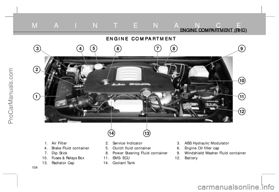
1. Air Filter 2. Service Indicator 3. ABS Hydraulic Modulator
4 . Brake Fluid container 5. Clutch fluid container 6. Engine Oil filler cap
7. Dip Stick 8. Power Steering Fluid container 9. Windshield Washer Fluid container
10. Fuses & Relays Box 11. EMS- ECU 12.Battery
13. Radiator Cap 14. Coolant Tank
ENGINE C ENGINE CENGINE C ENGINE C
ENGINE C
OMP OMPOMP OMP
OMP
AR ARAR AR
AR
T TT T
T
MENT MENTMENT MENT
MENT
38
11
9457
10
14
1
2
6
12
13
ProCarManuals.com
Page 117 of 161
117
L LL L
L
oad C oad Coad C oad C
oad C
onscious P onscious Ponscious P onscious P
onscious P
r rr r
r
essur essuressur essur
essur
e R e Re R e R
e R
educing educing educing educing
educing
V VV V
V
alv alvalv alv
alv
e (I e (Ie (I e (I
e (I
f fitt f fittf fitt f fitt
f fitt
ed) ed)ed) ed)
ed)
( Not applicable in ABS system) ( Not applicable in ABS system)( Not applicable in ABS system) ( Not applicable in ABS system)
( Not applicable in ABS system)
A load conscious pressure reducing valve eliminates the
possibility of rear wheels from locking and achieves optimum
braking in any load condition of the vehicle.
The valve, is fitted on RH long member connecting it to rear
axle through its link and control spring.
If any, alteration is done in rear suspension, the performance
of this valve will be impaired.
R RR R
R
emot emotemot emot
emot
e B e Be B e B
e B
y-pass y-pass y-pass y-pass
y-pass
V VV V
V
alv alvalv alv
alv
e (I e (Ie (I e (I
e (I
f fitt f fittf fitt f fitt
f fitt
ed) ed)ed) ed)
ed)
(Applicable in ABS system) (Applicable in ABS system)(Applicable in ABS system) (Applicable in ABS system)
(Applicable in ABS system)
The by-pass valve is provided in the rear brake circuit between
tandem master cylinder and ABS unit. The by-pass valve
bypasses the ABS unit in rear only braking (i.e. front brake
failed) condition. The feedback of front line pressure is
provided to the by-pass valve. in case of front brake failure,
the low front line presure being sensed by the by-pass valve
and the 100% brake line pressure from tandem master
cylinder is applied on to the rear brakes without reduction
in pressure.
M A I N T E N A N C EL LL L
L
CR CRCR CR
CR
V (IF FIT V (IF FITV (IF FIT V (IF FIT
V (IF FIT
TED), TED),TED), TED),
TED),
REMO REMO REMO REMO
REMO
TE BY P TE BY PTE BY P TE BY P
TE BY P
ASS ASS ASS ASS
ASS
V VV V
V
AL ALAL AL
AL
VE AND ECU VE AND ECUVE AND ECU VE AND ECU
VE AND ECU
ECU : ECU :ECU : ECU :
ECU :
DICOR engine common rail system consists of ECU, sensors
and actuators. The Electronic control unit (ECU) is a 32 bit
microprocessor which controls the injection parameters as well
as some of the vehicle related outputs. The ECU receives input
from various sensors located on the engine and the vehicle to
decide the injected quantity and injection timing best suited
for the engine to work with maximum efficiency and safety.
ECU is fitted inside the engine compartment.
C CC C
C
AUTIONS AUTIONSAUTIONS AUTIONS
AUTIONS
• •• •
•DO NOT DO NOT DO NOT DO NOT
DO NOT wash engine compartment with high
pressure water
• •• •
•DO NOT DO NOTDO NOT DO NOT
DO NOT tamper with ECU sensors and connectors
• •• •
•DO NOT DO NOTDO NOT DO NOT
DO NOT remove battery connections when the ignition
switch is in ‘ON’ position ( This may damage ECU)
• •• •
•AV AVAV AV
AV
OID OIDOID OID
OID jump start/push start, Use fully charged battery.
• •• •
•DO NO DO NODO NO DO NO
DO NO
T T T T
T run the vehicle if ‘CHECK ENGINE’ lamp on
dashboard is ‘ON.
• •• •
•If any abnormality in performance of engine occurs - like
lack of power- the vehicle to be taken to the
T TT T
T
A AA A
A
T TT T
T
A MO A MOA MO A MO
A MO
T TT T
T
ORS ORSORS ORS
ORS
authorised service outlet.
ProCarManuals.com
Page 118 of 161
118
B BB B
B
A AA A
A
T TT T
T
TER TERTER TER
TER
Y YY Y
Y
Battery BatteryBattery Battery
Battery
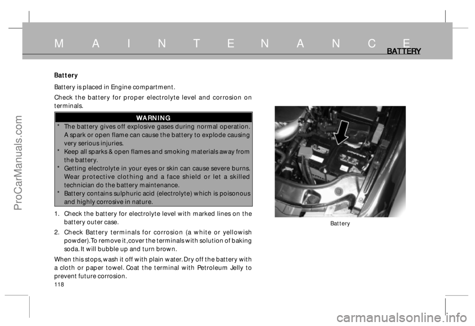
Battery is placed in Engine compartment.
Check the battery for proper electrolyte level and corrosion on
terminals.
W WW W
W
ARNING ARNINGARNING ARNING
ARNING
* The battery gives off explosive gases during normal operation.
A spark or open flame can cause the battery to explode causing
very serious injuries.
* Keep all sparks & open flames and smoking materials away from
the battery.
* Getting electrolyte in your eyes or skin can cause severe burns.
Wear protective clothing and a face shield or let a skilled
technician do the battery maintenance.
* Battery contains sulphuric acid (electrolyte) which is poisonous
and highly corrosive in nature.
1. Check the battery for electrolyte level with marked lines on the
battery outer case.
2. Check Battery terminals for corrosion (a white or yellowish
powder). To remove it, cover the terminals with solution of baking
soda. It will bubble up and turn brown.
When this stops, wash it off with plain water. Dry off the battery with
a cloth or paper towel. Coat the terminal with Petroleum Jelly to
prevent future corrosion.
Battery
M A I N T E N A N C E
ProCarManuals.com
Page 119 of 161
119
B BB B
B
A AA A
A
T TT T
T
TER TERTER TER
TER
Y YY Y
Y
,, ,,
,
ST ST ST ST
ST
AR ARAR AR
AR
TING TING TING TING
TING
THE ENGINE THE ENGINE THE ENGINE THE ENGINE
THE ENGINE
WITH JUMP LEADS WITH JUMP LEADSWITH JUMP LEADS WITH JUMP LEADS
WITH JUMP LEADS
The use of a wrench to loosen and remove cables from the
terminals should be made. Always disconnect the negative
(-ve) cable first and reconnect it last. Clean the battery
terminals with a terminal cleaning tool or wire brush.
Reconnect and tighten the cables, coat the terminals with
petroleum jelly. If you need to connect the battery to a
charger, disconnect both cables to prevent damage to the
vehicle’s electrical system.
NOTICE NOTICENOTICE NOTICE
NOTICE
Charging the battery with the cables connected can
seriously damage your vehicle’s electronic controls.
Detach the battery cables before connecting battery to
a charger.
* Swallowing electrolyte can cause fatal poisoning if
immediate action is not taken.
Starting the Engine with Jump Leads Starting the Engine with Jump LeadsStarting the Engine with Jump Leads Starting the Engine with Jump Leads
Starting the Engine with Jump Leads
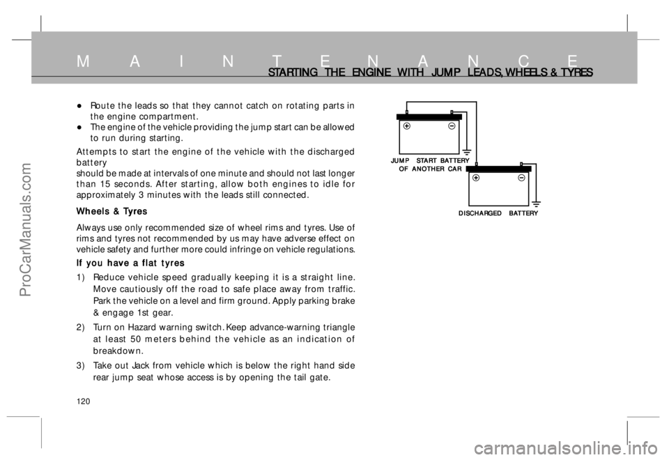
Your Safari with a discharged battery may be started by
transferring electrical power from a battery in another vehicle.
This may be dangerous as any deviation from the following
instructions could lead to personal injury or damage
resulting from battery explosion, as well as the damage to
the electrical systems in both vehicles.• Never expose the battery to open flames or sparks.
• Do not allow battery electrolyte to come in contact with
eyes, skins, fabrics or painted surfaces. The fluid
contains sulphuric acid which can cause injuries and
damage in the event of direct contact.
• To lessen the risk of injury wear eye protection when
working near any battery.
• Make sure that battery providing the jump start has the
same voltage as the battery in your vehicle (12 V). Its
capacity must not be substantially lower than that of the
discharged battery. The voltage and capacity are given
on the batteries.
• Do not disconnect the discharged battery from the vehicle.
• Switch off all unnecessary electrical loads.
• Do not lean over the battery during jump starting.
• Do not allow the terminals of one lead to touch those of
the other lead.
• Apply hand brake. Place gear shift lever to neutral.
Connect Leads in the Order as shown Connect Leads in the Order as shownConnect Leads in the Order as shown Connect Leads in the Order as shown
Connect Leads in the Order as shown
on next page on next page on next page on next page
on next page
•Do not connect lead to negative terminal of discharged
battery.
•The connection point should be as far away from the
discharged battery as possible.
M A I N T E N A N C E
ProCarManuals.com
Page 120 of 161
120
ST STST ST
ST
AR ARAR AR
AR
TING TING TING TING
TING
THE ENGINE THE ENGINE THE ENGINE THE ENGINE
THE ENGINE
WITH JUMP LEADS, WITH JUMP LEADS,WITH JUMP LEADS, WITH JUMP LEADS,
WITH JUMP LEADS,
WHEELS & WHEELS & WHEELS & WHEELS &
WHEELS &
T TT T
T
YRES YRESYRES YRES
YRES
•Route the leads so that they cannot catch on rotating parts in
the engine compartment.
•The engine of the vehicle providing the jump start can be allowed
to run during starting.
Attempts to start the engine of the vehicle with the discharged
battery
should be made at intervals of one minute and should not last longer
than 15 seconds. After starting, allow both engines to idle for
approximately 3 minutes with the leads still connected.
W WW W
W
heels & heels & heels & heels &
heels &
T TT T
T
yr yryr yr
yr
es eses es
es
Always use only recommended size of wheel rims and tyres. Use of
rims and tyres not recommended by us may have adverse effect on
vehicle safety and further more could infringe on vehicle regulations.
If you have a flat tyres If you have a flat tyresIf you have a flat tyres If you have a flat tyres
If you have a flat tyres
1) Reduce vehicle speed gradually keeping it is a straight line.
Move cautiously off the road to safe place away from traffic.
Park the vehicle on a level and firm ground. Apply parking brake
& engage 1st gear.
2) Turn on Hazard warning switch. Keep advance-warning triangle
at least 50 meters behind the vehicle as an indication of
breakdown.
3) Take out Jack from vehicle which is below the right hand side
rear jump seat whose access is by opening the tail gate.
M A I N T E N A N C E
JUMP ST JUMP STJUMP ST JUMP ST
JUMP ST
AR ARAR AR
AR
T B T BT B T B
T B
A AA A
A
T TT T
T
TER TERTER TER
TER
Y YY Y
Y
OF ANOTHER CAR OF ANOTHER CAROF ANOTHER CAR OF ANOTHER CAR
OF ANOTHER CAR
DISCHAR DISCHARDISCHAR DISCHAR
DISCHAR
GED B GED BGED B GED B
GED B
A AA A
A
T TT T
T
TER TERTER TER
TER
Y YY Y
Y
ProCarManuals.com
Page 127 of 161
127
Maintaining the car when not in extended use : Maintaining the car when not in extended use :Maintaining the car when not in extended use : Maintaining the car when not in extended use :
Maintaining the car when not in extended use :
Park the car in covered, dry and if possible well-ventilated
premises.
Engage a gear.
Remove the cables from the battery terminals (first remove
the cable from the negative terminal).
Make sure the handbrake is not engaged.
Clean and protect the painted parts using protective wax.
Clean and protect the shiny metal parts using commercially
available special compounds.
Sprinkle talcum powder on the rubber windscreen wiper and
rear window wiper blades and lift them off the glass.
Slightly open the windows.
Cover the car with a cloth or perforated plastic sheet. Do
not use sheets of imperforated plastic as they do not allow
moisture on the car body to evaporate.
Inflate the tyres to 0.5 bar above the normal specified
pressure and check it at regular intervals.
Check the battery charge every six weeks.
Do not drain the engine cooling system.
VEHICLE C VEHICLE CVEHICLE C VEHICLE C
VEHICLE C
ARE AREARE ARE
ARE
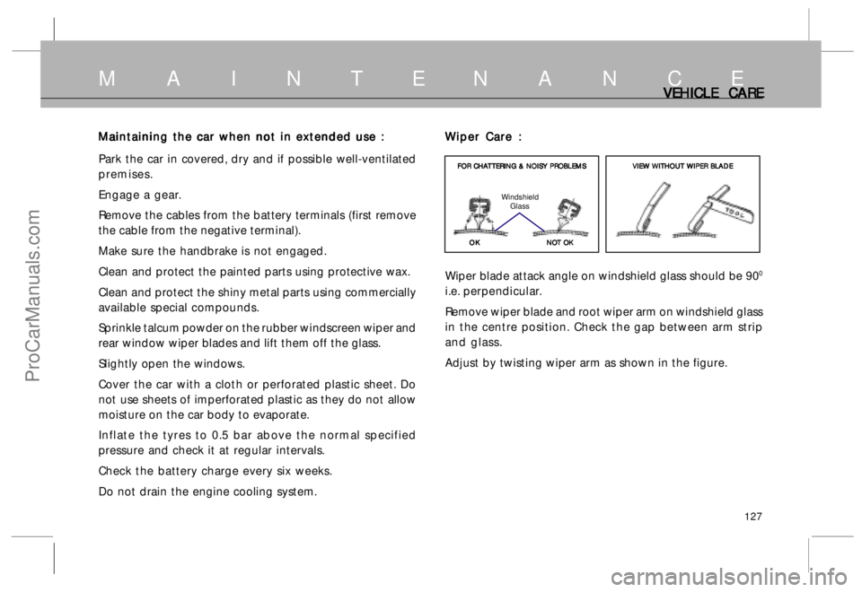
Wiper Care : Wiper Care :Wiper Care : Wiper Care :
Wiper Care :
Wiper blade attack angle on windshield glass should be 90
0
i.e. perpendicular.
Remove wiper blade and root wiper arm on windshield glass
in the centre position. Check the gap between arm strip
and glass.
Adjust by twisting wiper arm as shown in the figure.
OK OKOK OK
OK FOR CHA FOR CHAFOR CHA FOR CHA
FOR CHA
T TT T
T
TERING & NOISY PR TERING & NOISY PRTERING & NOISY PR TERING & NOISY PR
TERING & NOISY PR
OBLEMS OBLEMSOBLEMS OBLEMS
OBLEMS
NO NONO NO
NO
T OK T OKT OK T OK
T OK Windshield
GlassVIE VIEVIE VIE
VIE
W W W W
W
WITHOUT WITHOUT WITHOUT WITHOUT
WITHOUT
WIPER BL WIPER BLWIPER BL WIPER BL
WIPER BL
ADE ADEADE ADE
ADE
M A I N T E N A N C E
ProCarManuals.com