audio TOYOTA 4RUNNER 2022 Owners Manual
[x] Cancel search | Manufacturer: TOYOTA, Model Year: 2022, Model line: 4RUNNER, Model: TOYOTA 4RUNNER 2022Pages: 616, PDF Size: 12.01 MB
Page 7 of 616
7
1
8 7
6
5
4
3
2
9
4RUNNER (U)What to do if...
(Troubleshooting) .................... 586
Alphabetical index...................... 591
Index
For vehicles with a audio/navigation system, refer to the “NAVI GATION
AND MULTIMEDIA SYSTEM OWNER’S MANUAL” for information regard-
ing the audio/navigation system.
Page 19 of 616
19Pictorial index
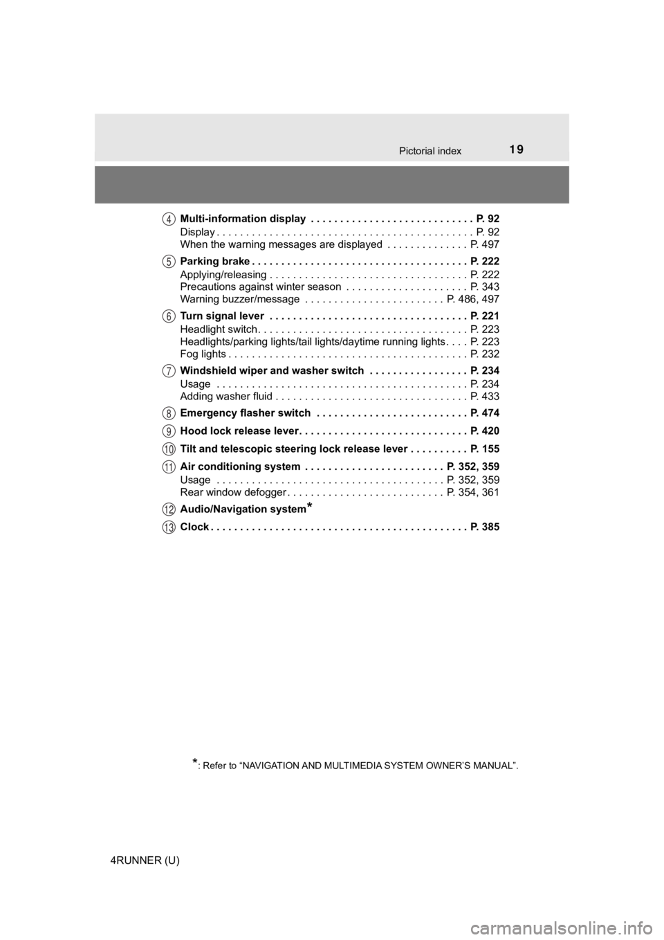
4RUNNER (U)Multi-information display . . . . . . . . . . . . . . . . . . . . . . . . . . . . P. 92
Display . . . . . . . . . . . . . . . . . . . . . . . . . . . . . . . . . . . . . . . . . . . . P. 92
When the warning messages are displayed . . . . . . . . . . . . . . P. 497
Parking brake . . . . . . . . . . . . . . . . . . . . . . . . . . . . . . . . . . . . . P. 222
Applying/releasing . . . . . . . . . . . . . . . . . . . . . . . . . . . . . . . . . . P. 222
Precautions against winter season . . . . . . . . . . . . . . . . . . . . . P. 343
Warning buzzer/message . . . . . . . . . . . . . . . . . . . . . . . . P. 486, 497
Turn signal lever . . . . . . . . . . . . . . . . . . . . . . . . . . . . . . . . . . P. 221
Headlight switch . . . . . . . . . . . . . . . . . . . . . . . . . . . . . . . . . . . . P. 223
Headlights/parking lights/tail lights/daytime running lights . .
. . P. 223
Fog lights . . . . . . . . . . . . . . . . . . . . . . . . . . . . . . . . . . . . . . . . . P. 232
Windshield wiper and washer switch . . . . . . . . . . . . . . . . . P. 234
Usage . . . . . . . . . . . . . . . . . . . . . . . . . . . . . . . . . . . . . . . . . . . P. 234
Adding washer fluid . . . . . . . . . . . . . . . . . . . . . . . . . . . . . . . . . P. 433
Emergency flasher switch . . . . . . . . . . . . . . . . . . . . . . . . . . P. 474
Hood lock release lever. . . . . . . . . . . . . . . . . . . . . . . . . . . . . P. 420
Tilt and telescopic steering lock release lever . . . . . . . . . . P. 155
Air conditioning system . . . . . . . . . . . . . . . . . . . . . . . . P. 352, 359
Usage . . . . . . . . . . . . . . . . . . . . . . . . . . . . . . . . . . . . . . . P. 352, 359
Rear window defogger . . . . . . . . . . . . . . . . . . . . . . . . . . . P. 354, 361
Audio/Navigation system
*
Clock . . . . . . . . . . . . . . . . . . . . . . . . . . . . . . . . . . . . . . . . . . . . P. 385
*: Refer to “NAVIGATION AND MULT IMEDIA SYSTEM OWNER’S MANUAL”.
4
5
6
7
8
9
10
11
12
13
Page 22 of 616
22Pictorial index
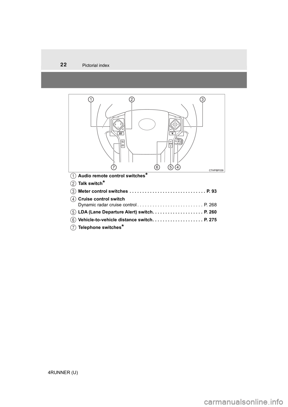
4RUNNER (U)Audio remote control switches
*
Talk switch*
Meter control switches . . . . . . . . . . . . . . . . . . . . . . . . . . . . . . P. 93
Cruise control switch
Dynamic radar cruise control . . . . . . . . . . . . . . . . . . . . . . . . . . P. 268
LDA (Lane Departure Alert) switch. . . . . . . . . . . . . . . . . . . . P. 260
Vehicle-to-vehicle distance switch . . . . . . . . . . . . . . . . . . . . P. 275
Telephone switches
*
1
2
3
4
5
6
7
Page 94 of 616
942. Instrument cluster
4RUNNER (U)
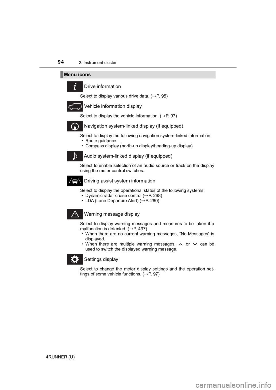
Drive information
Select to display various drive data. (P. 95)
Vehicle information display
Select to display the vehicle information. ( P. 97)
Navigation system-linked display (if equipped)
Select to display the following navigation system-linked information.
• Route guidance
• Compass display (north-up display/heading-up display)
Audio system-linked display (if equipped)
Select to enable selection of an audio source or track on the d isplay
using the meter control switches.
Driving assist system information
Select to display the operational status of the following syste ms:
• Dynamic radar cruise control ( P. 268)
• LDA (Lane Departure Alert) ( P. 260)
Warning message display
Select to display warning messages and measures to be taken if a
malfunction is detected. ( P. 497)
• When there are no current warning messages, “No Messages” is displayed.
• When there are multiple warning messages, or can be used to switch the displayed warning message.
Settings display
Select to change the meter display settings and the operation set-
tings of some vehicle functions. ( P. 97)
Menu icons
Page 109 of 616
1093-1. Key information
3
Operation of each component
4RUNNER (U)■
Replacing the battery
P. 455
■ Confirmation of the registered key number
The number of keys already registered to the vehicle can be confirmed. Ask
your Toyota dealer for details.
■ If a wrong key is used (vehicles with a smart key system)
The key cylinder rotates freely to isolate inside mechanism.
NOTICE
■To prevent key damage
● Do not drop the keys, subject them to strong shocks or bend them.
● Do not expose the keys to high temperatures for long periods of time.
● Do not get the keys wet or wash them in an ultrasonic washer etc.
● Do not attach metallic or magnetic materials to the keys or place the keys
close to such materials.
● Do not disassemble the keys.
● Do not attach a sticker or anything else to the surface of the electronic key
and key (with a wireless remote control function).
● Vehicles with a smart key system: Do not place the keys near objects that
produce magnetic fields, such as TVs, audio systems and induction cook-
ers, or medical electrical equipment, such as low-frequency therapy equip-
ment.
■ Carrying the electronic key on your person (vehicles with a sma rt key
system)
Carry the electronic key 3.9 in. (10 cm) or more away from electric appli-
ances that are turned on. Radio waves emitted from electric app liances
within 3.9 in. (10 cm) of the electronic key may interfere with the key, caus-
ing the key to not function properly.
■ In case of a smart key system malfunction or other key-related prob-
lems (vehicles with a smart key system)
Take your vehicle with all the electronic keys provided with your vehicle to
your Toyota dealer.
■ When an electronic key is lost (vehicles with a smart key system)
If the electronic key remains lost, the risk of vehicle theft i ncreases signifi-
cantly. Visit your Toyota dealer immediately with all remaining electronic
keys that was provided with your vehicle.
Page 123 of 616

1233-2. Opening, closing and locking the doors
3
Operation of each component
4RUNNER (U)■
Conditions affecting operation
The smart key system uses weak radio waves. In the following si tuations, the
communication between the electronic key and the vehicle may be affected,
preventing the smart key system, wireless remote control and en gine immobi-
lizer system from operating properly. (Ways of coping: P. 520)
● When the electronic key battery is depleted
● Near a TV tower, electric power plant, gas station, radio stati on, large dis-
play, airport or other facility that generates strong radio wav es or electrical
noise
● When carrying a portable radio, cellular phone, cordless phone or other
wireless communication device
● When the electronic key is in contact with, or is covered by the following
metallic objects
• Cards to which aluminum foil is attached
• Cigarette boxes that have aluminum foil inside
• Metallic wallets or bags
• Coins
• Hand warmers made of metal
• Media such as CDs and DVDs
● When multiple electronic keys are in the vicinity
● When other wireless keys (that emit radio waves) are being used nearby
● When carrying the electronic key together with the following devices that
emit radio waves
• Another vehicle’s electronic key or a wireless key that emits radio waves
• Personal computers or personal digital assistants (PDAs)
• Digital audio players
• Portable game systems
● If window tint with a metallic content or metallic objects are attached to the
back window
● When the electronic key is placed near a battery charger or ele ctronic
devices
● When the vehicle is parked in a pay parking spot where radio wa ves are
emitted.
If the doors cannot be locked/unlocked using the smart key syst em, lock/
unlock the doors by performing any of the following:
● Bring the electronic key close to either front door handle and operate the
entry function.
● Operate the wireless remote control.
If the doors cannot be locked/unlocked using the above methods, use the
mechanical key. ( P. 520)
If the engine cannot be started using the smart key system, ref er to P. 521.
Page 207 of 616
207
4
Driving
4RUNNER (U)
4-2. Driving procedures
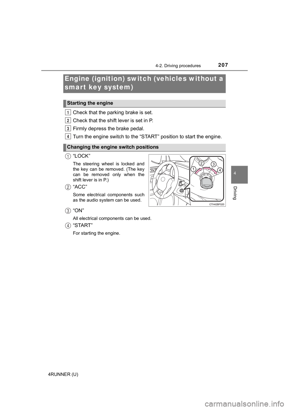
Check that the parking brake is set.
Check that the shift lever is set in P.
Firmly depress the brake pedal.
Turn the engine switch to the “S TART” position to start the engine.
“LOCK”
The steering wheel is locked and
the key can be removed. (The key
can be removed only when the
shift lever is in P.)
“ACC”
Some electrical components such
as the audio system can be used.
“ON”
All electrical components can be used.
“START”
For starting the engine.
Engine (ignition) switch (vehicles without a
smart key system)
Starting the engine
Changing the engine switch positions
1
2
3
4
1
2
3
4
Page 211 of 616
2114-2. Driving procedures
4
Driving
4RUNNER (U)
Stop the vehicle.
Set the parking brake (
P. 222), and shift the shift lever to P.
Press the engine switch.
Release the brake pedal and check that “ACCESSORY” or “IGNI-
TION ON” is not shown on the meter.
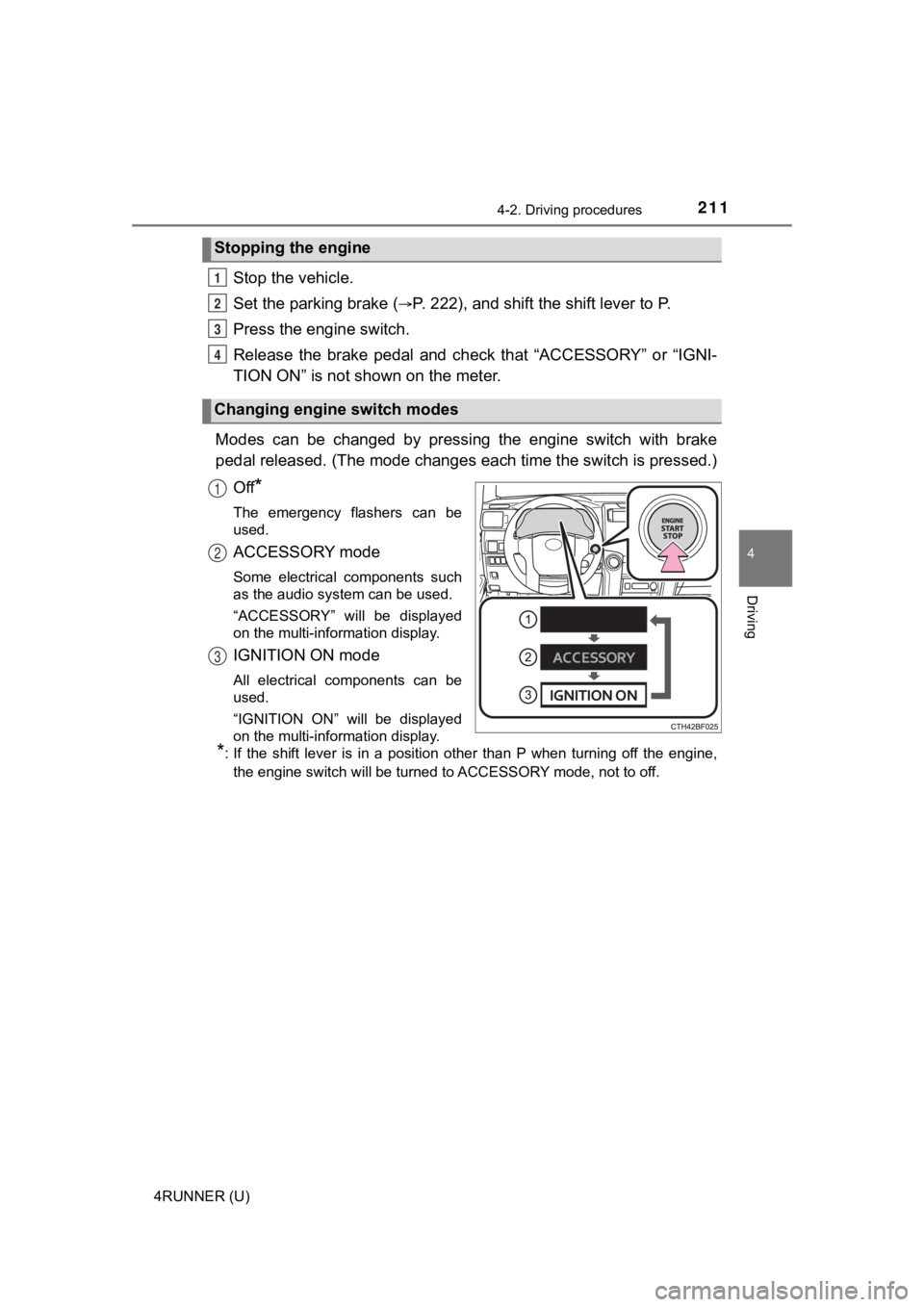
Modes can be changed by pressing the engine switch with brake
pedal released. (The mode changes each time the switch is pressed.)
Off
*
The emergency flashers can be
used.
ACCESSORY mode
Some electrical components such
as the audio system can be used.
“ACCESSORY” will be displayed
on the multi-information display.
IGNITION ON mode
All electrical components can be
used.
“IGNITION ON” will be displayed
on the multi-information display.
*: If the shift lever is in a position other than P when turning off the engine, the engine switch will be turned to ACCESSORY mode, not to off.
Stopping the engine
Changing engine switch modes
1
2
3
4
1
2
3
Page 265 of 616
2654-5. Using the driving support systems
4
Driving
4RUNNER (U)
■Operation conditions of each function
●Lane departure alert function
This function operates when all of the following conditions are met.
• LDA is turned on.
• Vehicle speed is approximately 32 mph (50 km/h) or more.
• System recognizes white (yellow) lines.
• Width of traffic lane is approximately 9.8 ft. (3 m) or more.
• Turn signal lever is not operated.
• Vehicle is driven on a straight road or around a gentle curve with a radius
of more than approximately 492 ft. (150 m).
• No system malfunctions are detected. ( P. 267)
● Vehicle sway warning function
This function operates when all of the following conditions are met.
• Setting for “Sway Warning” in of the multi-information display is set to “On”. ( P. 98)
• Vehicle speed is approximately 32 mph (50 km/h) or more.
• Width of traffic lane is approximately 9.8 ft. (3 m) or more.
• No system malfunctions are detected. ( P. 267)
■ Temporary cancellation of functions
When the operation conditions are no longer met, a function may be tempo-
rarily canceled. However, when the operation conditions are met again, oper-
ation of the function is automatically restored. ( P. 265)
■ Lane departure alert function
The warning buzzer may be difficult to hear due to external noi se, audio play-
back, etc.
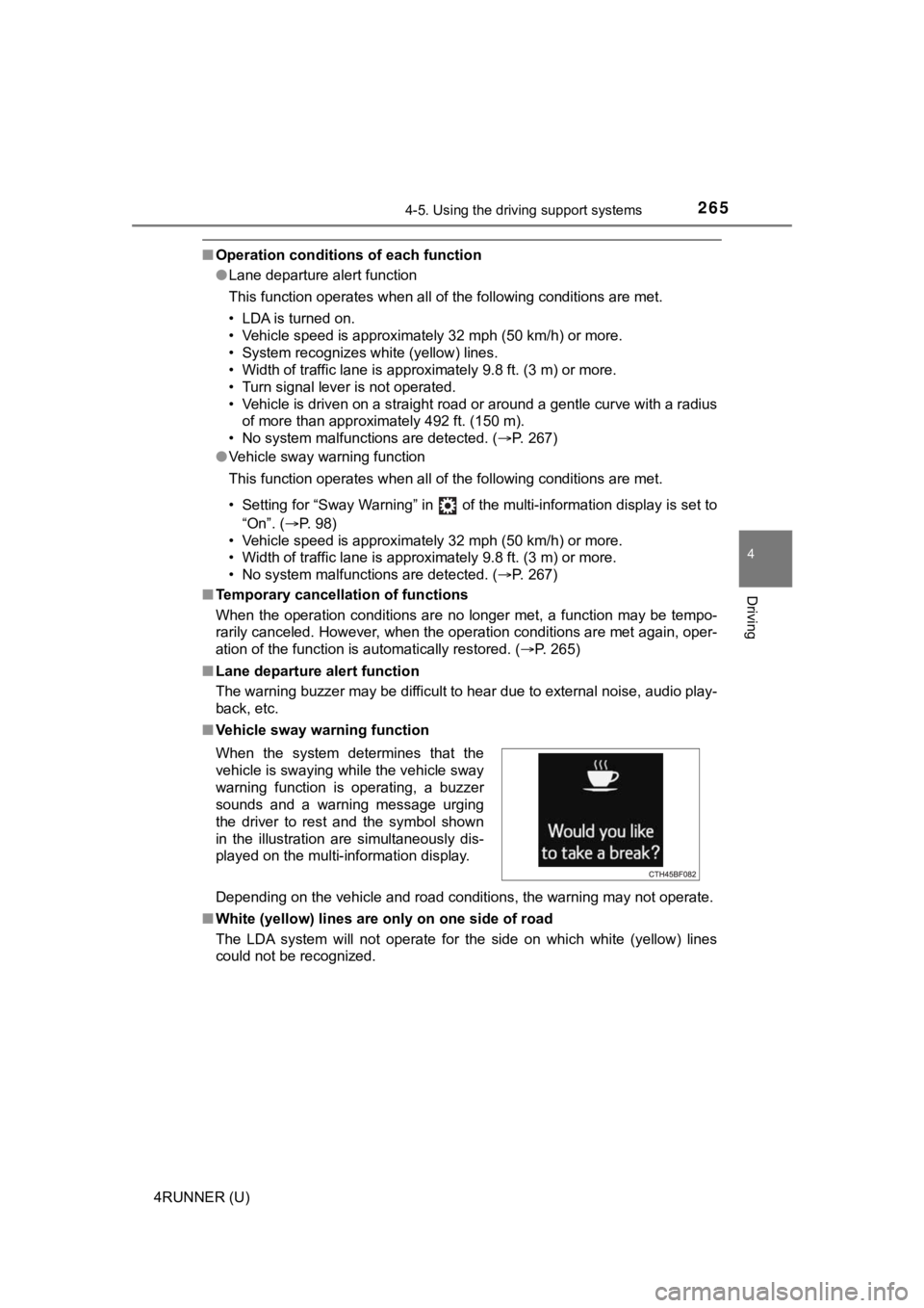
■ Vehicle sway warning function
Depending on the vehicle and road conditions, the warning may n ot operate.
■ White (yellow) lines are only on one side of road
The LDA system will not operate for the side on which white (yellow) lines
could not be recognized.
When the system determines that the
vehicle is swaying while the vehicle sway
warning function is operating, a buzzer
sounds and a warning message urging
the driver to rest and the symbol shown
in the illustration are simultaneously dis-
played on the multi-information display.
Page 292 of 616

2924-5. Using the driving support systems
4RUNNER (U)
■Intuitive parking assist can be operated when
●Front corner sensors:
• The engine switch is in the “ON” position (without a smart key system) or
the engine switch is in IGNITION ON mode (with a smart key syst em).
• The shift lever is in a position other than P.
• The vehicle speed is less than approximately 6 mph (10 km/h).
● Rear corner and rear center sensors:
• The engine switch is in the “ON” position (without a smart key system) or
the engine switch is in IGNITION ON mode (with a smart key syst em).
• The shift lever is in R.
■ Intuitive parking assist display
When an obstacle is detected while the Toyota parking assist mo nitor is in
use, the warning indicator will appear in the upper part of the screen even if
the display setting has been set to off.
■ Sensor detection information
●The sensor’s detection areas are limited to the areas around th e vehicle’s
front corner and rear bumpers.
● The following situations may occur during use.
• Depending on the shape of the obstacle and other factors, the detection
distance may shorten, or detection may be impossible.
• Obstacles may not be detected if they are too close to the sen sor.
• There will be a short delay between obstacle detection and dis play. Even
at slow speeds, there is a possibility that the obstacle will c ome within the
sensor’s detection areas before the display is shown and the wa rning
beep sounds.
• Thin posts or objects lower than the sensor may not be detected for colli-
sion when approached, even if they have been detected once.
• It might be difficult to hear beeps due to the volume of audio system or air
flow noise of air conditioning system.
■ Objects which the system may not be properly detected
●Wires, fences, ropes, etc.
● Cotton, snow and other materials that absorb sound waves
● Sharply-angled objects
● Low obstacles
● Tall obstacles with upper sections projecting outwards in the d irection of
your vehicle