030G6±04
± SERVICE SPECIFICATIONSPOWER STEERING
03±59
AVENSIS REPAIR MANUAL (RM1018E)
POWER STEERING
SERVICE DATA
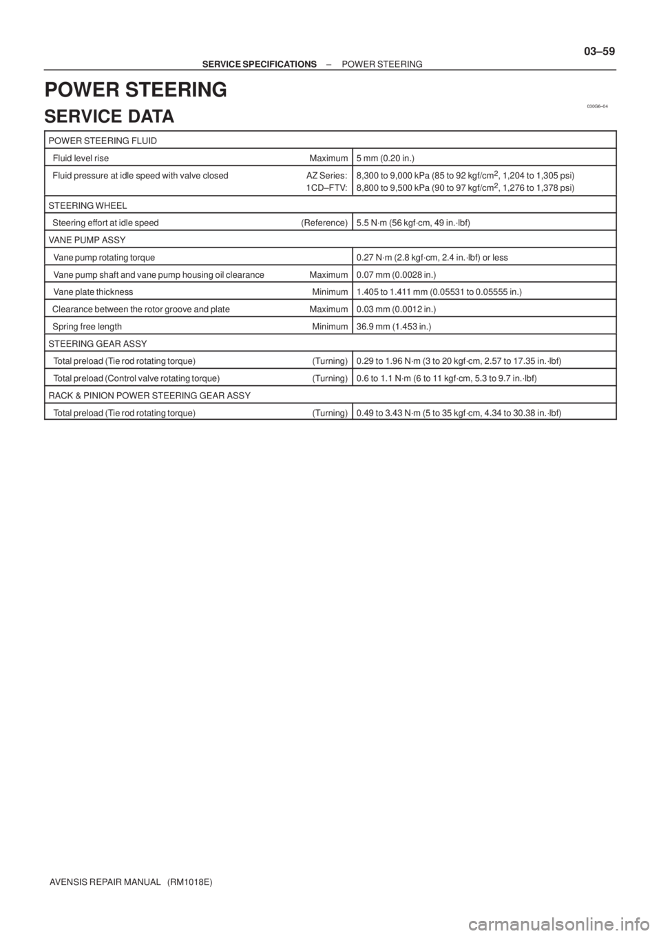
POWER STEERING FLUID
Fluid level rise Maximum5 mm (0.20 in.)
Fluid pressure at idle speed with valve closed AZ Series:
1CD±FTV:8,300 to 9,000 kPa (85 to 92 kgf/cm2, 1,204 to 1,305 psi)
8,800 to 9,500 kPa (90 to 97 kgf/cm2, 1,276 to 1,378 psi)
STEERING WHEEL
Steering effort at idle speed (Reference)5.5 N´m (56 kgf´cm, 49 in.´lbf)
VANE PUMP ASSY
Vane pump rotating torque0.27 N´m (2.8 kgf´cm, 2.4 in.´lbf) or less
Vane pump shaft and vane pump housing oil clearance Maximum0.07 mm (0.0028 in.)
Vane plate thickness Minimum1.405 to 1.411 mm (0.05531 to 0.05555 in.)
Clearance between the rotor groove and plate Maximum0.03 mm (0.0012 in.)
Spring free length Minimum36.9 mm (1.453 in.)
STEERING GEAR ASSY
Total preload (Tie rod rotating torque) (Turning)0.29 to 1.96 N´m (3 to 20 kgf´cm, 2.57 to 17.35 in.´lbf)
Total preload (Control valve rotating torque) (Turning)0.6 to 1.1 N´m (6 to 11 kgf´cm, 5.3 to 9.7 in.´lbf)
RACK & PINION POWER STEERING GEAR ASSY
Total preload (Tie rod rotating torque) (Turning)0.49 to 3.43 N´m (5 to 35 kgf´cm, 4.34 to 30.38 in.´lbf)
700TJ±01
B56435
Slide
B61414
Slide
B66957
Butyl TapeMirror Base
a
b c d 70±64
± WINDSHIELD/WINDOWGLASS/MIRRORINNER REAR VIEW MIRROR ASSY
AVENSIS REPAIR MANUAL (RM1018E)
INNER REAR VIEW MIRROR ASSY
REPLACEMENT
HINT:
The installation is in the reverse order of the removal. However, when there is a special point concerning
the installation, it is indicated.
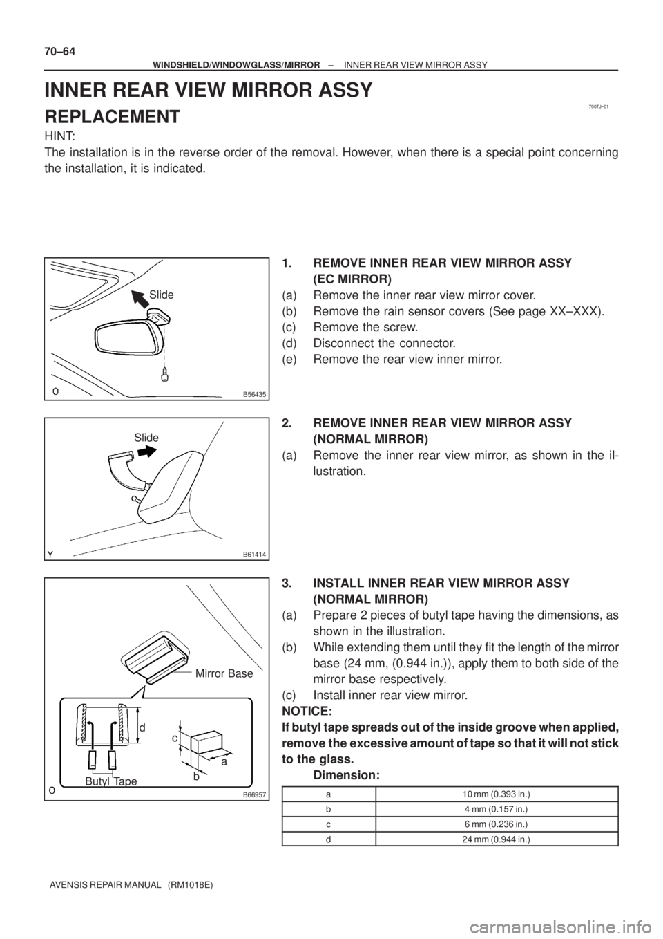
1. REMOVE INNER REAR VIEW MIRROR ASSY
(EC MIRROR)
(a) Remove the inner rear view mirror cover.
(b) Remove the rain sensor covers (See page XX±XXX).
(c) Remove the screw.
(d) Disconnect the connector.
(e) Remove the rear view inner mirror.
2. REMOVE INNER REAR VIEW MIRROR ASSY
(NORMAL MIRROR)
(a) Remove the inner rear view mirror, as shown in the il-
lustration.
3. INSTALL INNER REAR VIEW MIRROR ASSY
(NORMAL MIRROR)
(a) Prepare 2 pieces of butyl tape having the dimensions, as
shown in the illustration.
(b) While extending them until they fit the length of the mirror
base (24 mm, (0.944 in.)), apply them to both side of the
mirror base respectively.
(c) Install inner rear view mirror.
NOTICE:
If butyl tape spreads out of the inside groove when applied,
remove the excessive amount of tape so that it will not stick
to the glass.
Dimension:
a10 mm (0.393 in.)
b4 mm (0.157 in.)
c6 mm (0.236 in.)
d24 mm (0.944 in.)