service TOYOTA AVENSIS 2003 Service Repair Manual
[x] Cancel search | Manufacturer: TOYOTA, Model Year: 2003, Model line: AVENSIS, Model: TOYOTA AVENSIS 2003Pages: 2234, PDF Size: 56.77 MB
Page 1850 of 2234
2AVENSIS (EWD526E)
A INTRODUCTION
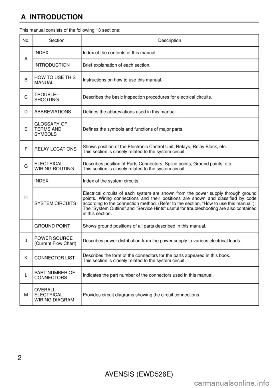
This manual consists of the following 13 sections:
No.
SectionDescription
INDEXIndex of the contents of this manual.
A
INTRODUCTIONBrief explanation of each section.
BHOW TO USE THIS
MANUALInstructions on how to use this manual.
CTROUBLE–
SHOOTINGDescribes the basic inspection procedures for electrical circuits.
DABBREVIATIONSDefines the abbreviations used in this manual.
E
GLOSSARY OF
TERMS AND
SYMBOLS
Defines the symbols and functions of major parts.
FRELAY LOCATIONSShows position of the Electronic Control Unit, Relays, Relay Block, etc.\
This section is closely related to the system circuit.
GELECTRICAL
WIRING ROUTINGDescribes position of Parts Connectors, Splice points, Ground points, et\
c.
This section is closely related to the system circuit.
INDEXIndex of the system circuits.
H
SYSTEM CIRCUITS
Electrical circuits of each system are shown from the power supply through ground
points. Wiring connections and their positions are shown and classified \
by code
according to the connection method. (Refer to the section, ”How to u\
se this manual”).
The ”System Outline” and ”Service Hints” useful for troubles\
hooting are also contained
in this section.
IGROUND POINTShows ground positions of all parts described in this manual.
JPOWER SOURCE
(Current Flow Chart)Describes power distribution from the power supply to various electrical\
loads.
KCONNECTOR LISTDescribes the form of the connectors for the parts appeared in this book\
.
This section is closely related to the system circuit.
LPART NUMBER OF
CONNECTORSIndicates the part number of the connectors used in this manual.
M
OVERALL
ELECTRICAL
WIRING DIAGRAM
Provides circuit diagrams showing the circuit connections.
http://vnx.su
Page 1854 of 2234
[N]
[O] [P]
[Q] [R]
[S]
[T]
[U]
6 AVENSIS (EWD526E)
B HOW TO USE THIS MANUAL
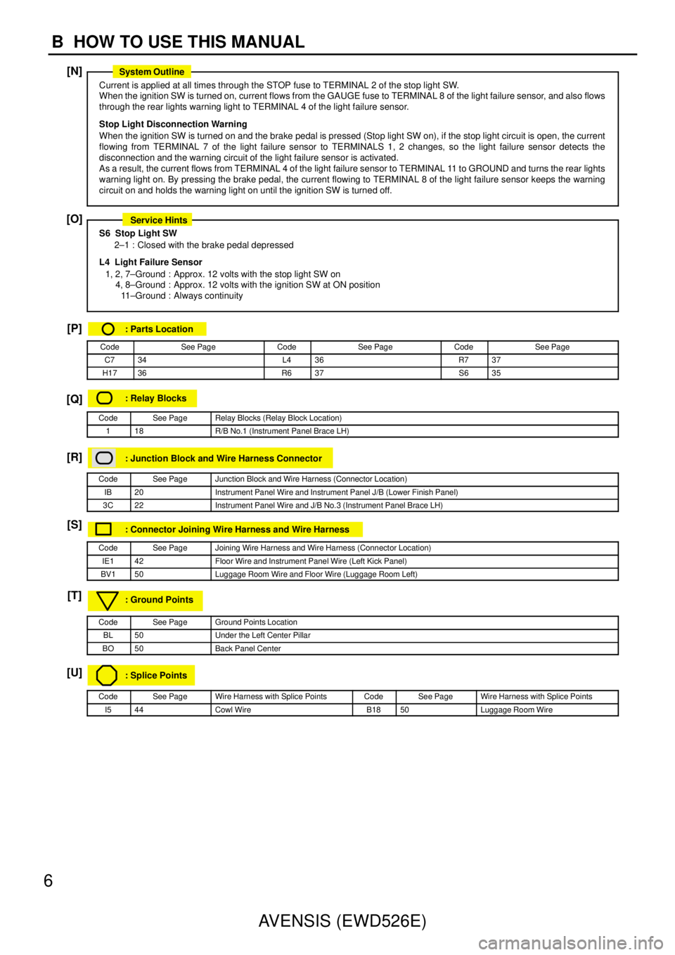
Current is applied at all times through the STOP fuse to TERMINAL 2 of the stop light SW.
When the ignition SW is turned on, current flows from the GAUGE fuse to TERM\
INAL 8 of the light failure sensor, and also flows
through the rear lights warning light to TERMINAL 4 of the light failure sensor\
.
Stop Light Disconnection Warning
When the ignition SW is turned on and the brake pedal is pressed (Stop ligh\
t SW on), if the stop light circuit is open, the cur
rent
flowing from TERMINAL 7 of the light failure sensor to TERMINALS 1, 2 changes, \
so the light failure sensor detects the
disconnection and the warning circuit of the light failure sensor is activated.
As a result, the current flows from TERMINAL 4 of the light failure sens\
or to TERMINAL 11 to GROUND and turns the rear lights
warning light on. By pressing the brake pedal, the current flowing to TERMINAL \
8 of the light failure sensor keeps the warning
circuit on and holds the warning light on until the ignition SW is turne\
d off.
S6 Stop Light SW
2–1 : Closed with the brake pedal depressed
L4 Light Failure Sensor 1, 2, 7–Ground : Approx. 12 volts with the stop light SW on 4, 8–Ground : Approx. 12 volts with the ignition SW at ON position11 –Ground : Always continuity
: Parts Location
CodeSee PageCodeSee PageCodeSee Page
C734L436R737
H1736R637S635
: Relay Blocks
CodeSee PageRelay Blocks (Relay Block Location)
118R/B No.1 (Instrument Panel Brace LH)
: Junction Block and Wire Harness Connector
CodeSee PageJunction Block and Wire Harness (Connector Location)
IB20Instrument Panel Wire and Instrument Panel J/B (Lower Finish Panel)
3C22Instrument Panel Wire and J/B No.3 (Instrument Panel Brace LH)
: Connector Joining Wire Harness and Wire Harness
CodeSee PageJoining Wire Harness and Wire Harness (Connector Location)
IE142Floor Wire and Instrument Panel Wire (Left Kick Panel)
BV150Luggage Room Wire and Floor Wire (Luggage Room Left)
: Ground Points
CodeSee PageGround Points Location
BL50Under the Left Center Pillar
BO50Back Panel Center
: Splice Points
CodeSee PageWire Harness with Splice PointsCodeSee PageWire Harness with Splice Points
I544Cowl WireB1850Luggage Room Wire
System Outline
Service Hints
http://vnx.su