relay TOYOTA AVENSIS 2003 Service Repair Manual
[x] Cancel search | Manufacturer: TOYOTA, Model Year: 2003, Model line: AVENSIS, Model: TOYOTA AVENSIS 2003Pages: 2234, PDF Size: 56.95 MB
Page 1850 of 2234
2AVENSIS (EWD526E)
A INTRODUCTION
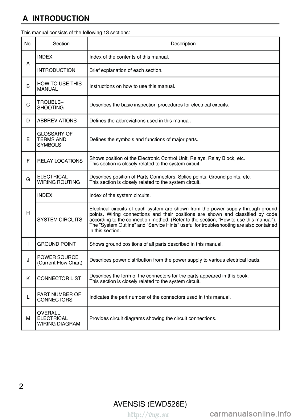
This manual consists of the following 13 sections:
No.
SectionDescription
INDEXIndex of the contents of this manual.
A
INTRODUCTIONBrief explanation of each section.
BHOW TO USE THIS
MANUALInstructions on how to use this manual.
CTROUBLE–
SHOOTINGDescribes the basic inspection procedures for electrical circuits.
DABBREVIATIONSDefines the abbreviations used in this manual.
E
GLOSSARY OF
TERMS AND
SYMBOLS
Defines the symbols and functions of major parts.
FRELAY LOCATIONSShows position of the Electronic Control Unit, Relays, Relay Block, etc.\
This section is closely related to the system circuit.
GELECTRICAL
WIRING ROUTINGDescribes position of Parts Connectors, Splice points, Ground points, et\
c.
This section is closely related to the system circuit.
INDEXIndex of the system circuits.
H
SYSTEM CIRCUITS
Electrical circuits of each system are shown from the power supply through ground
points. Wiring connections and their positions are shown and classified \
by code
according to the connection method. (Refer to the section, ”How to u\
se this manual”).
The ”System Outline” and ”Service Hints” useful for troubles\
hooting are also contained
in this section.
IGROUND POINTShows ground positions of all parts described in this manual.
JPOWER SOURCE
(Current Flow Chart)Describes power distribution from the power supply to various electrical\
loads.
KCONNECTOR LISTDescribes the form of the connectors for the parts appeared in this book\
.
This section is closely related to the system circuit.
LPART NUMBER OF
CONNECTORSIndicates the part number of the connectors used in this manual.
M
OVERALL
ELECTRICAL
WIRING DIAGRAM
Provides circuit diagrams showing the circuit connections.
http://vnx.su
Page 1851 of 2234
3
HOW TO USE THIS MANUAL B
This manual provides information on the electrical circuits installed on\
vehicles by
dividing them into a circuit for each system.
The actual wiring of e")
AVENSIS (EWD526E)3
HOW TO USE THIS MANUAL B
This manual provides information on the electrical circuits installed on\
vehicles by
dividing them into a circuit for each system.
The actual wiring of each system circuit is shown from the point where t\
he power
source is received from the battery as far as each ground point. (All c\
ircuit
diagrams are shown with the switches in the OFF position.)
When troubleshooting any problem, first understand the operation of the \
circuit
where the problem was detected (see System Circuit section), the power\
source
supplying power to that circuit (see Power Source section), and the ground poin\
ts
(see Ground Point section). See the System Outline to understand the c\
ircuit
operation.
When the circuit operation is understood, begin troubleshooting of the p\
roblem
circuit to isolate the cause. Use Relay Location and Electrical Wiring Routing
sections to find each part, junction block and wiring harness connectors, wiring\
harness and wiring harness connectors, splice points, and ground points \
of each
system circuit. Internal wiring for each junction block is also provided for b\
etter
understanding of connection within a junction block.
Wiring related to each system is indicated in each system circuit by arr\
ows
(from__, to__). When overall connections are required, see the Overall\
Electrical
Wiring Diagram at the end of this manual.
http://vnx.su
Page 1853 of 2234
AVENSIS (EWD526E)5
B
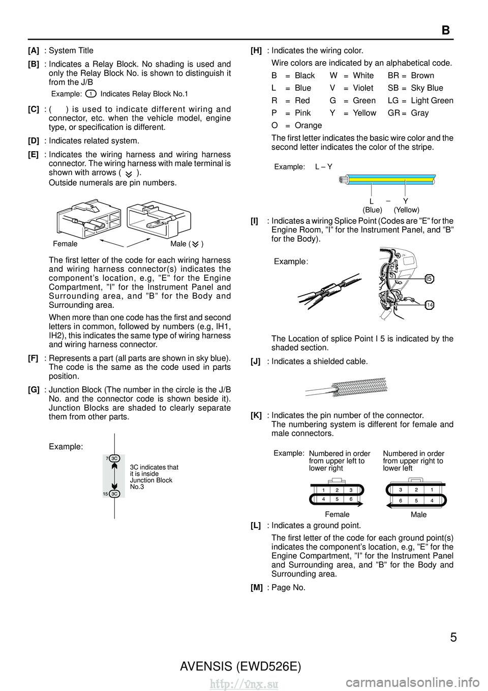
[A]
: System Title
[B] : Indicates a Relay Block. No shading is used and
only the Relay Block No. is shown to distinguish it
from the J/B
Example: Indicates Relay Block No.1
[C] : ( ) is used to indicate different wiring and
connector, etc. when the vehicle model, engine
type, or specification is different.
[D] : Indicates related system.
[E] : Indicates the wiring harness and wiring harness
connector. The wiring harness with male terminal is
shown with arrows (
).
Outside numerals are pin numbers.
Female Male ( )
The first letter of the code for each wiring harness
and wiring harness connector(s) indicates the
component’s location, e.g, ”E” for the Engine
Compartment, ”I” for the Instrument Panel and
Surrounding area, and ”B” for the Body and
Surrounding area.
When more than one code has the first and second
letters in common, followed by numbers (e.g, IH1,
IH2), this indicates the same type of wiring harness
and wiring harness connector.
[F] : Represents a part (all parts are shown in sky blue).
The code is the same as the code used in parts
position.
[G] : Junction Block (The number in the circle is the J/B
No. and the connector code is shown beside it).
Junction Blocks are shaded to clearly separate
them from other parts.
3C indicates that
it is inside
Junction Block
No.3
Example:
[H] : Indicates the wiring color.
Wire colors are indicated by an alphabetical code.
B = Black W = White BR = Brown
L = Blue V = Violet SB = Sky Blue
R = Red G = Green LG = Light Green
P = Pink Y = Yellow GR = Gray
O = Orange
The first letter indicates the basic wire color and the
second letter indicates the color of the stripe.
Example: L – Y
L
(Blue) Y
(Yellow)
[I] : Indicates a wiring Splice Point (Codes are ”E” for the
Engine Room, ”I” for the Instrument Panel, and ”B”
for the Body).
The Location of splice Point I 5 is indicated by the
shaded section.
[J] : Indicates a shielded cable.
[K]: Indicates the pin number of the connector.
The numbering system is different for female and
male connectors.
Example: Numbered in order
from upper left to
lower right Numbered in order
from upper right to
lower left
Female Male
[L]: Indicates a ground point.
The first letter of the code for each ground point(s)
indicates the component’s location, e.g, ”E” for the
Engine Compartment, ”I” for the Instrument Panel
and Surrounding area, and ”B” for the Body and
Surrounding area.
[M] : Page No.
http://vnx.su
Page 1854 of 2234
[N]
[O] [P]
[Q] [R]
[S]
[T]
[U]
6 AVENSIS (EWD526E)
B HOW TO USE THIS MANUAL
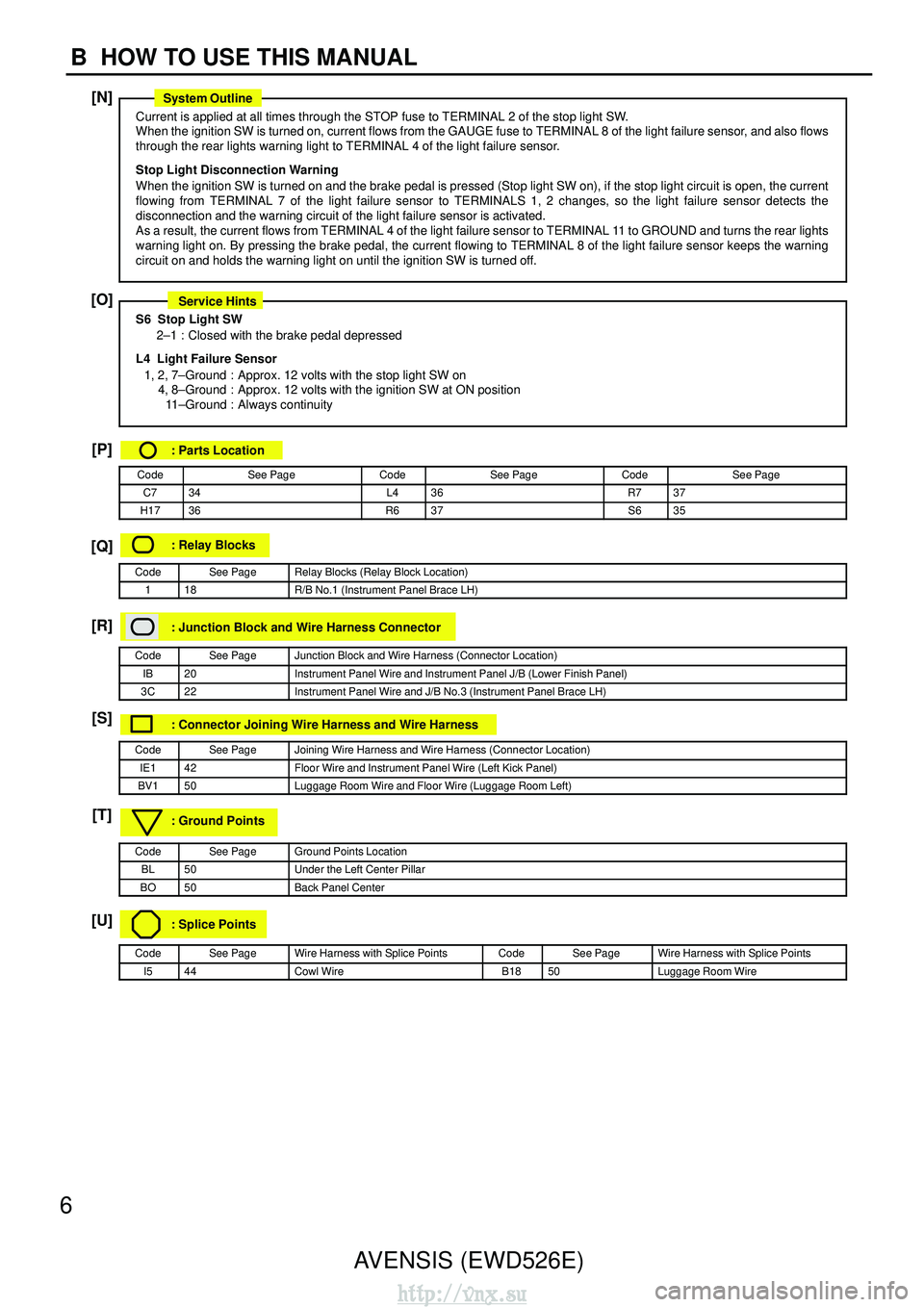
Current is applied at all times through the STOP fuse to TERMINAL 2 of the stop light SW.
When the ignition SW is turned on, current flows from the GAUGE fuse to TERM\
INAL 8 of the light failure sensor, and also flows
through the rear lights warning light to TERMINAL 4 of the light failure sensor\
.
Stop Light Disconnection Warning
When the ignition SW is turned on and the brake pedal is pressed (Stop ligh\
t SW on), if the stop light circuit is open, the cur
rent
flowing from TERMINAL 7 of the light failure sensor to TERMINALS 1, 2 changes, \
so the light failure sensor detects the
disconnection and the warning circuit of the light failure sensor is activated.
As a result, the current flows from TERMINAL 4 of the light failure sens\
or to TERMINAL 11 to GROUND and turns the rear lights
warning light on. By pressing the brake pedal, the current flowing to TERMINAL \
8 of the light failure sensor keeps the warning
circuit on and holds the warning light on until the ignition SW is turne\
d off.
S6 Stop Light SW
2–1 : Closed with the brake pedal depressed
L4 Light Failure Sensor 1, 2, 7–Ground : Approx. 12 volts with the stop light SW on 4, 8–Ground : Approx. 12 volts with the ignition SW at ON position11 –Ground : Always continuity
: Parts Location
CodeSee PageCodeSee PageCodeSee Page
C734L436R737
H1736R637S635
: Relay Blocks
CodeSee PageRelay Blocks (Relay Block Location)
118R/B No.1 (Instrument Panel Brace LH)
: Junction Block and Wire Harness Connector
CodeSee PageJunction Block and Wire Harness (Connector Location)
IB20Instrument Panel Wire and Instrument Panel J/B (Lower Finish Panel)
3C22Instrument Panel Wire and J/B No.3 (Instrument Panel Brace LH)
: Connector Joining Wire Harness and Wire Harness
CodeSee PageJoining Wire Harness and Wire Harness (Connector Location)
IE142Floor Wire and Instrument Panel Wire (Left Kick Panel)
BV150Luggage Room Wire and Floor Wire (Luggage Room Left)
: Ground Points
CodeSee PageGround Points Location
BL50Under the Left Center Pillar
BO50Back Panel Center
: Splice Points
CodeSee PageWire Harness with Splice PointsCodeSee PageWire Harness with Splice Points
I544Cowl WireB1850Luggage Room Wire
System Outline
Service Hints
http://vnx.su
Page 1856 of 2234

B HOW TO USE THIS MANUAL
The ground points circuit diagram shows the connections from all major p\
arts to the respective ground points. When
troubleshooting a faulty ground point,")
8AVENSIS (EWD526E)
B HOW TO USE THIS MANUAL
The ground points circuit diagram shows the connections from all major p\
arts to the respective ground points. When
troubleshooting a faulty ground point, checking the system circuits which use a common \
ground may help you identify
the problem ground quickly. The relationship between ground points (
EA, IB and IC shown below) can also be
checked this way.
5
5
5
5
44 4
4
4
BA1 5 IB1
8 EA2
ID115
IC3 3
IA1
2
E 3
W–B W–B W–B
W–B
W–B
W–B
W–B
W–B
W–BW –B
W–B
W–BW –B
W–B
W–BW –BW –B
W–B
W–B W–B
W–B
W–B
W–B
W–B
W–BW –BW–B
W–B
BR
W–B
BR BR
W–B W–B
W–B
W–B
W–B
W–B
W–B
W–BW –B
W–B
W–B
W–B
W–B
W–BBR
W–B
BR
BR
BR
W–B (4A–GZE)
W–B
W–B I 2
I 2
B 5
I 5 I 5
I 5
B 5
B 5
B 5
I 5
I 5 I 3
I 3
E 3
E 3
E 3
E 2
E 4
E 5
E 4
E 5
E 6
E 4 E 4
B 4
EA
I 4
B 4
B 4
I 4 I 8
IB IC
4
4 3E
5
3E 6
3G
13
3F
3
3D
1
3B
7 W–B
W–B
W–B
W–B
W–B
W–B
W–B
W–B
W–BW–B
W–B
W–B
W–B
W–B
W–B I 6
I 6
I 2
3C 7
10 A A
A
A
A
A
Junction
Connector J 1
W–B
W–B
W–BW –B
BR
W–B
W–B
W–B
W–B
W–B
W–B
I GROUND POINT
FAN MAIN Relay
FAN MAIN Relay
A/C Relay No.2
A/C Relay No.3
Radiator Fan Motor
Headlight Cleaner Relay
Headlight LH
Headlight RH
Front Fog Light LH
Brake Fluid Level SW Front Fog Light RH
Front Turn Signal Light RH
Front Clearance Light RH
Front Turn Signal Light LH
Front Clearance Light LH
Door Lock Control SW
Door Courtesy SW RH
Door Lock Motor RH
Door Lock Control Relay
Blower Resistor
Idle–Up SW
A/C Amplifier
Radio and Player
HEATER Relay
Auto Antenna Motor A/C Control Assembly
Blower Motor
Blower SW
Parking Brake SW
Combination Meter
Combination SW
Cruise Control ECU
Remote Control Mirror SW
Turn Signal Flasher
Defogger SW
Unlock Warning SW
Power Window Master SW
Power Window Control
Relay
Door Courtesy SW LH
Door Lock Control SW
Door Lock Motor LH
Fuel Control SW
Woofer Speaker Amplifier
Combination Meter
Combination Meter
Fuel Sender
Cigarette Lighter
O/D Main SW
Clock
Combination SW
∗The system shown here is an EXAMPLE ONLY. It is different to the actual circuit shown in the SYSTEM CIRCUITS SECTION.
http://vnx.su
Page 1857 of 2234
9
B
The
”Current Flow Chart” section, describes which parts each power source (fuses, fusible links\
, and circuit breakers)
transmits current to. In the Power Source circuit dia")
AVENSIS (EWD526E)9
B
The
”Current Flow Chart” section, describes which parts each power source (fuses, fusible links\
, and circuit breakers)
transmits current to. In the Power Source circuit diagram, the condition\
s when battery power is supplied to each system
are explained. Since all System Circuit diagrams start from the power so\
urce, the power source system must be fully
understood.
ACC
S 2 6
6
5 2
22
Battery 30A AM2
Starter Short Pin
100A ALT
Fusible Link Block
60A ABS10A ECU–B
7.5A DOME
15A EFI
10A HAZARD
20A RADIO NO.1
10A HORN
20A
10A Fuse
Page
214
230
11 2
122 194
187
180
166
210
ABS
Cigarette Lighter
Combination Meter
Key Reminder and Seat Belt Warning
Light Auto Turn Off
Theft Deterrent and Door Lock ControlABS and Traction Control
Cruise Control
Electronically Controlled Transmission
Multiplex Communication System
STOP System
DOME Headlight
Interior Light
3 EA2 1 EA1E 6
E 7
E 7
2
2
2
2 2
2 2
2
INJECTION Relay
STARTER Relay
B
B
B
B–O
1
1 2
23
4
3
4
W–B W–B
B–W
B–W
E 7
E 7 B
B W
1.25B FL MAIN
50A MAIN
7.5A AM2
15A HAZ–RADIO
2
2 2
2
2W
W EB1
EB1
7
6
W–R I 2 I 2 I 2
WW
W
W W
1 1
1 140A DOOR LOCK CB
7.5A DOME
1
W–L
R
1
1
2
43 1
11
1
1 1 1
G
G
W–R
15A TAIL
20A DEFOG
B–Y
84
32Ignition SW I 8
B–Y 1 1P–L
Battery
15A RAD CIG2
TAIL
Relay
Power Source
J POWER SOURCE (Current Flow Chart)
Engine Room R/B (See Page 20)
2
W W
B
B
B
B
B
W–RWW
W
G–W AM2
AM1
IG2
IG1 W
W
The chart below shows the route by which current flows from the battery \
to each electrical source
(Fusible Link, Circuit Breaker, Fuse, etc.) and other parts.
∗ The system shown here is an EXAMPLE ONLY. It is different to the actual circuit shown in the SYSTEM CIRCUITS SECTION.
http://vnx.su
Page 1859 of 2234
A 1
L PART NUMBER OF CONNECTORS
A/C Ambient Temp. Sensor
Code
90980–11070Part Number
D 4 Diode (Courtesy)
Code
90980–11608
A 2 A/C Condenser Fan Motor 90980–11237 D 5 Diode (Interior Light) 90980–10962
A 3 A/C Condenser Fan Relay 90980–10940 D 6 Diode (Moon Roof) 90980–11608
A 4 A/C Condenser Fan Resistor 90980–10928
90980–11271D 7 Door Lock Control Relay
90980–10848
A 5 A/C Magnetic Clutch
90980–11413D 8 Door Lock Control SW LH
90980–11148
A 6 A/T Oil Temp. Sensor
90980–11151D 9 Door Lock Control SW RH
A 7 ABS Actuator 90980–11009Door Courtesy SW LH
90980–11097
A 8 ABS Actuator
90980–10941Door Courtesy SW RH
A 9 ABS Speed Sensor Front LH
90980–11002Door Courtesy SW Front LH
ABS Speed Sensor Front RH
90980–11856Door Courtesy SW Front RH
90980–11156
Airbag Sensor Front LH Door Courtesy SW Rear LH
Airbag Sensor Front RH Door Courtesy SW Rear RH
A10
A11
A12
A13 Airbag Squib
90980–11194Door Key Lock and Unlock SW LH
90980–11170
90980–11070 D10
D11
D12
D13
D14
D15
D16
D17 Door Key Lock and Unlock SW RH Part Number
Part Name
Part Name
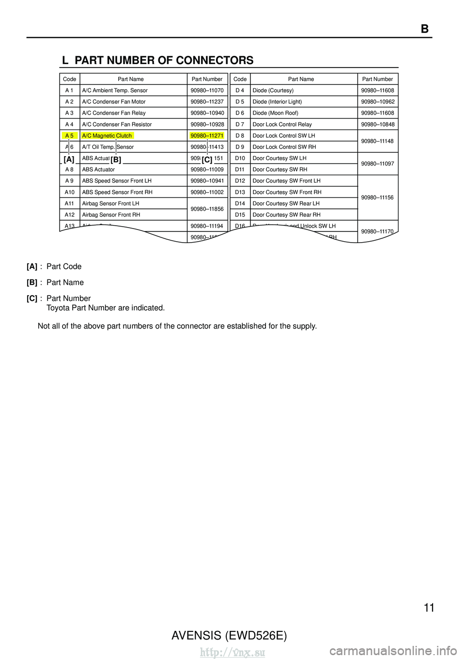
[A]
[B] [C]
AVENSIS (EWD526E) 11
B
[A]
: Part Code
[B] : Part Name
[C] : Part Number
Toyota Part Number are indicated.
Not all of the above part numbers of the connector are established for t\
he supply.
http://vnx.su
Page 1860 of 2234
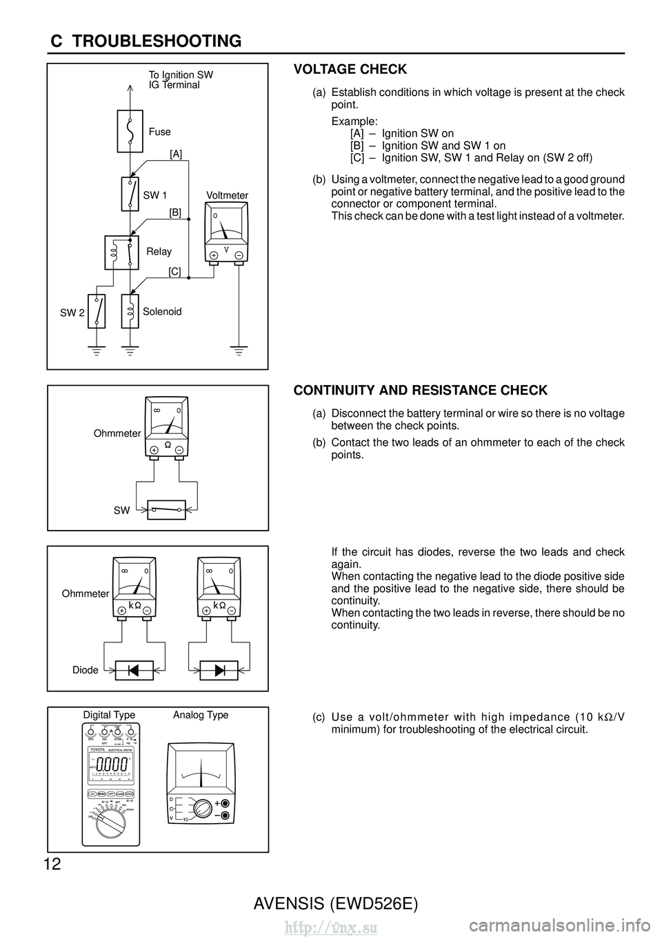
To Ignition SW
IG Terminal
FuseVoltmeter
SW 1
Relay
SW 2 Solenoid[A]
[B]
[C]
Ohmmeter
SW
OhmmeterDiode
Digital Type Analog Type
12 AVENSIS (EWD526E)
C TROUBLESHOOTING
VOLTAGE CHECK
(a) Establish conditions in which voltage is present at the check
point.
Example:[A] – Ignition SW on
[B] – Ignition SW and SW 1 on
[C] – Ignition SW, SW 1 and Relay on (SW 2 off)
(b) Using a voltmeter, connect the negative lead to a good ground point or negative battery terminal, and the positive lead to the
connector or component terminal.
This check can be done with a test light instead of a voltmeter.
CONTINUITY AND RESISTANCE CHECK
(a) Disconnect the battery terminal or wire so there is no voltage
between the check points.
(b) Contact the two leads of an ohmmeter to each of the check points.
If the circuit has diodes, reverse the two leads and check
again.
When contacting the negative lead to the diode positive side
and the positive lead to the negative side, there should be
continuity.
When contacting the two leads in reverse, there should be no
continuity.
(c) Use a volt/ohmmeter with high impedance (10 k Ω/V
minimum) for troubleshooting of the electrical circuit.
http://vnx.su
Page 1861 of 2234
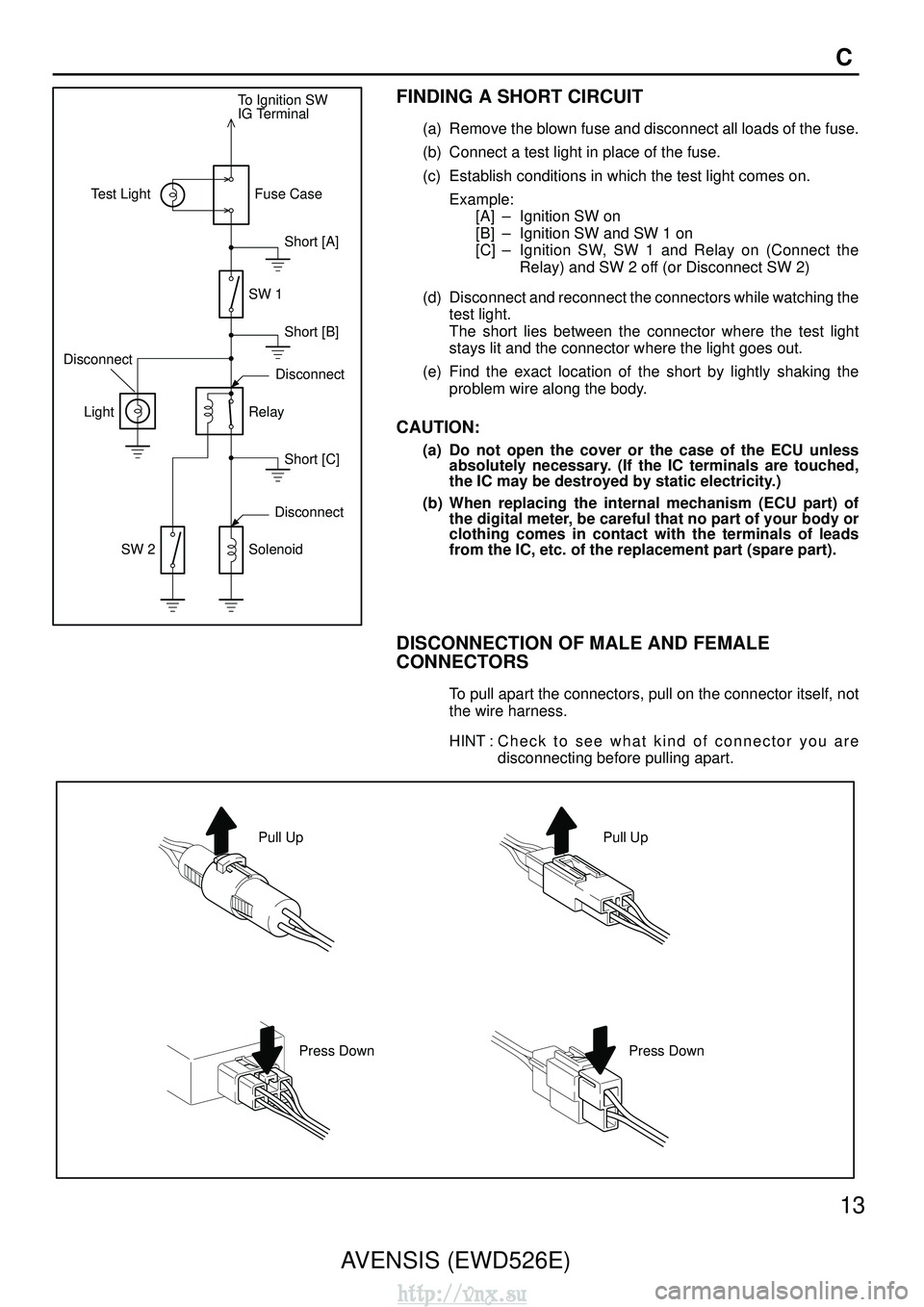
To Ignition SW
IG Terminal
Test Light
Relay
Light
SW 2 Solenoid DisconnectShort [A]
Disconnect
Disconnect SW 1Fuse Case
Short [B]
Short [C]
Pull Up
Press Down Press Down Pull Up
AVENSIS (EWD526E)
13
C
FINDING A SHORT CIRCUIT
(a) Remove the blown fuse and disconnect all loads of the fuse.
(b) Connect a test light in place of the fuse.
(c) Establish conditions in which the test light comes on.
Example:[A]–Ignition SW on
[B] –Ignition SW and SW 1 on
[C] –Ignition SW, SW 1 and Relay on (Connect the
Relay) and SW 2 off (or Disconnect SW 2)
(d) Disconnect and reconnect the connectors while watching the test light.
The short lies between the connector where the test light
stays lit and the connector where the light goes out.
(e) Find the exact location of the short by lightly shaking the problem wire along the body.
CAUTION:
(a) Do not open the cover or the case of the ECU unlessabsolutely necessary. (If the IC terminals are touched,
the IC may be destroyed by static electricity.)
(b) When replacing the internal mechanism (ECU part) of the digital meter, be careful that no part of your body or
clothing comes in contact with the terminals of leads
from the IC, etc. of the replacement part (spare part).
DISCONNECTION OF MALE AND FEMALE
CONNECTORS
To pull apart the connectors, pull on the connector itself, not
the wire harness.
HINT : C h e c k t o s e e w h a t k i n d o f c onnector you are
disconnecting before pulling apart.
http://vnx.su
Page 1865 of 2234
 and are not treated as being
abbreviations.
AVENSIS (EWD526E) 17
ABBREVIATIONS D
ABBREVIATIONS
The followin")
∗The titles given inside the components are the names of the terminals (\
terminal codes) and are not treated as being
abbreviations.
AVENSIS (EWD526E) 17
ABBREVIATIONS D
ABBREVIATIONS
The following abbreviations are used in this manual.
A/C = Air Conditioner
A/T = Automatic Transaxle
ABS = Anti–Lock Brake System
CIS = Commonwealth of Independent States
DLC3 = Data Link Connector 3
EC = Electrochromic
ECT = Electronic Control Transmission
ECU = Electronic Control Unit
EFI = Electronic Fuel Injection
EGR = Exhaust Gas Recirculation
EPS = Electric Power Steering
ESA = Electronic Spark Advance
EVAP = Evaporative Emission
HID = High Intensity Discharge
INT = Intermittent
ISC = Idle Speed Control
J/B = Junction Block
L/B = Liftback Type
LH = Left–Hand
LHD = Left–Hand Drive
M/T = Manual Transaxle
PTC = Positive Temperature Coefficient
R/B = Relay Block
RH = Right–Hand
RHD = Right–Hand Drive
S/D = Sedan Type
SRS = Supplemental Restraint System
SW = Switch
TEMP. = Temperature
TRC = Traction Control
VRV = Vacuum Regulating Valve
VSC = Vehicle Stability Control
VSV = Vacuum Switching Valve
VVT = Variable Valve Timing
VVT–i = Variable Valve Timing–intelligent
W/G = Wagon Type
w/ = With
w/o = Without
http://vnx.su