catalytic converter TOYOTA AVENSIS 2005 Service Owner's Guide
[x] Cancel search | Manufacturer: TOYOTA, Model Year: 2005, Model line: AVENSIS, Model: TOYOTA AVENSIS 2005Pages: 5135, PDF Size: 95.28 MB
Page 4337 of 5135

− DIAGNOSTICSECD SYSTEM (1CD−FTV)(From September, 2003)
05−259
AVENSIS Supplement (RM1045E)
(d)DIAGNOSTICS TROUBLE CODE DESCRIPTION FOR TOYOTA D−CAT:
DTC No.Description
P0031Open or short in A/F sensor or heater circuit (Low output)
P0544Open or short in exhaust gas temperature sensor circuit (Up stream)
P0545Open or short in exhaust gas temperature sensor circuit (Up stream) (Low output)
P0546Open or short in exhaust gas temperature sensor circuit (Up stream) (High output)
P1386TOYOTA D−CAT fuel addition system malfunction
P1425Open or short in differential pressure sensor circuit
P1426Differential pressure sensor is clogged or has incorrect vacuum hose arrangement
P1427Open or short in differential pressure sensor circuit (Low output)
P1428Open or short in differential pressure sensor circuit (High output)
P2002DPNR Catalytic converter malfunction
P2031Open or short in exhaust gas temperature sensor circuit (Down stream)
P2032Open or short in exhaust gas temperature sensor circuit (Down stream) (Low output)
P2033Open or short in exhaust gas temperature sensor circuit (Down stream) (High output)
P2047Open in exhaust fuel addition injector circuit
P2238Open or short in A/F sensor or heater circuit (Low output)
P2239Open or short in A/F sensor or heater circuit (High output)
Page 4338 of 5135

A91221
Common Rail System Diagram (1CD−FTV Fuel System):
Sensors ECM EDU
Common Rail
Fuel Pressure SensorPressure Discharge
Valve
Supply Pump Assy
Suction Control Valve
Fuel TankMain
Injector
Fuel Filter
: High−pressurized Area
Exhaust Fuel
Addition Injector
Exhaust Port
To DPNR
Catalytic
Converter 05−260
− DIAGNOSTICSECD SYSTEM (1CD−FTV)(From September, 2003)
AVENSIS Supplement (RM1045E)
3. COMMON RAIL SYSTEM DESCRIPTION
(a)COMMON RAIL SYSTEM:
The common rail system stores high−pressurized fuel supplied from the supply pump in the common rail and
injects it using the injectors. Fuel injection timing and fuel injection volume are regulated by the ECM; it pro-
vides an electric current to the solenoid valve of the injector with the EDU to regulate them.
By storing high−pressurized fuel produced in the supply pump in the common rail, this system can always
offer stable fuel injection pressure regardless of the engine speed and engine load, even if a driving speed
is low. In addition, this system uses the injector that opens and closes its fuel passage with the Two−Wa y
Valve (TWV) therefore both the fuel injection time and volume are precisely regulated by the ECM.
The ECM monitors internal fuel pressure of the common rail with the fuel pressure sensor and commands
the supply pump to supply fuel to obtain a target internal pressure, approximately 30 to180 MPa (306 to
1,835 kgf/cm
2, 4,351to 26,106 psi). The ECM opens and closes the pressure discharge valve to improve
controllability for the common rail internal fuel pressure.
This system has two split fuel injections. It performs ”pilot−injection” as subsidiary fuel injection prior to the
main fuel injection to make combustion soft, and this helps to reduce engine vibration and noise.
Page 4392 of 5135
A85357
DPNR (Diesel Particulate−NOx Reduction System) Catalyst Monolithic Construction:
NO, PM
HC, CO N2, CO2
H
2O
Exhaust Gas Temperature
Sensor (on up stream) ECM
Exhaust Gas Temperature
Sensor (on down stream)
Wall −Flow Type:
Differential Pressure Sensor
Cross Section
Magnified ViewGas Flow
PM
Exhaust Gas
DPNR (Diesel Particulate −NOx Reduction System):
DPNR Catalytic
Converter
05
−466
−
DIAGNOSTICS ECD SYSTEM (1CD −FTV)(From September, 2003)
AVENSIS Supplement (RM 1045E)
DTC P2002 PARTICULATE TRAP EFFICIENCY BELOW
THRESHOLD (BANK 1)
HINT:
S For more information on the DPNR (* 1) catalytic converter and TOYOTA D −CAT (*2), see page
05 −255.
S If P2002 is present, refer to the diagnostic trouble codes (DTCs) table for TOYOTA D −CAT on page
05 −255.
* 1 : Diesel Particulate −NOx Reduction system.
*2: Diesel Clean Advanced Technology.
CIRCUIT DESCRIPTION
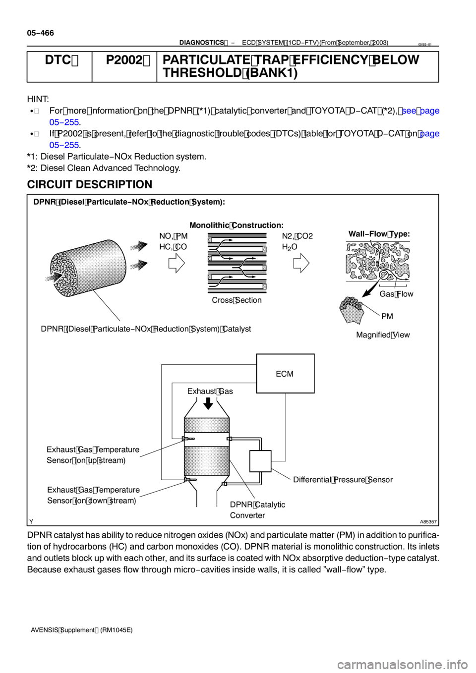
DPNR catalyst has ability to reduce nitrogen oxides (NOx) and particulate matter (PM) in addition to purifica-
tion of hydrocarbons (HC) and carbon monoxides (CO). DPNR material is monolithic construction. Its inlets
and outlets block up with each other, and its surface is coated with NOx absorptive deduction −type catalyst.
Because exhaust gases flow through micro −cavities inside walls, it is called ”wall −flow” type.
05I83 −01
Page 4393 of 5135

A91205
Malfunction Detection:
DPNR Catalyst Regeneration
(Activation of Fuel Addition)
Approximately 300_C (572_F) OFFON
NormalMore than
Approximately 600_C(1,112_F)
Abnormal
Time Exhaust Gas Temperature
− DIAGNOSTICSECD SYSTEM (1CD−FTV)(From September, 2003)
05−467
AVENSIS Supplement (RM1045E) DTC No.
DTC Detection ConditionTrouble Area
P2002
Condition (a) or (b) is met (1trip detection logic):
(a) Differential pressure exceeds a standard level for more than
10 seconds
(b) Exhaust gas temperature does not raise during DPNR cata-
lyst regeneration
SDPNR catalytic converter (Manifold converter sub−assy)
SDifferential pressure sensor
SDifferential pressure sensor vacuum hose is clogged
SBlockage in Vacuum transmitting pipe sub−assy
SExhaust gas temperature sensor
SExhaust gas leaks in TOYOTA D−CAT
SMass air flow meter
SECM
MONITOR DESCRIPTION
In order to detect abnormality in the DPNR (*3) catalytic converter, the ECM monitors an exhaust gas temper-
ature as well as a differential pressure of the exhaust gas. For monitoring the differential pressure, the ECM
compares the up−and downstream pressure of the DPNR catalytic converter. If the difference between the
pressure is large, the ECM judges that the DPNR has contaminated or deteriorated, and then illuminates
the CHK ENG.
Furthermore, the ECM monitors increase in the exhaust gas temperature while the exhaust fuel addition in-
jector adds fuel under DPNR catalyst regeneration. The exhaust gas temperature during the DPNR catalyst
regeneration normally rises from approximately 300_C (572_F) to approximately 600_C(1,112_F) or higher.
If the temperature does not rise even if a certain period of time has elapsed, the ECM interprets this as mal-
function of the DPNR and illuminates the CHK ENG.
*3: Diesel Particulate−NOx Reduction system.
INSPECTION PROCEDURE
HINT:
SRead freeze frame data usingthe hand−held tester.Freeze frame data records the engine conditions
when a malfunction is detected. When troubleshooting, freeze frame data can help determine if the
vehicle was running or stopped, if the engine was warmed up or not, if the air−fuel ratio was lean or
rich, and other data from the time the malfunction occurred.
SIf (exhaust gas) differential pressure (DPNR DIFF PRESS) of the DPNR catalytic converter does not
virtually develop when increasing the engine speed, the DPNR catalytic converter may be malfunction-
ing.
Page 4398 of 5135

A85356
ECM
Exhaust Gas
Exhaust Gas Differential Pressure (kPa)
Differential Pressure Voltage (V)
1.530
0.750
0.530
0
−5.020.0100.0 Detect P1425 or P1428
5.000
4.700 4.800
0 0.400
Differential Pressure
Sensor
Property of Output Voltage:
Detect P1425 or P1427
DPNR Catalytic
Converter 05−458
− DIAGNOSTICSECD SYSTEM (1CD−FTV)(From September, 2003)
AVENSIS Supplement (RM1045E)
CIRCUIT DESCRIPTION
Two sensible portions of the differential pressure sensor are mounted before and after the DPNR (*2) catalyt-
ic converter and monitor exhaust gas differential pressure. The sensor itself is located far from the engine
assembly to reduce the influence of vibration, and is a semiconductor−type that is not influenced by exhaust
gases.
The ECM compares the exhaust gas pressure before and after DPNR catalytic converter by monitoring the
pressure using the up−and downstream sensible portions of the differential pressure sensor. If difference
between the pressure before and after the catalytic converter exceeds a standard level, the ECM judges
that the catalytic converter has clogged with particulate matter (PM). When once the ECM judges it, the ECM
begins to exercise the DPNR catalyst regeneration.
When output voltage of the sensor deviates from the normal operating range, the ECM interprets this as
malfunction of the sensor circuit, and sets DTC P1425, P1427, or P1428 and then illuminates the CHK ENG.
*2: Diesel Particulate−NOx Reduction system.
HINT:
If vacuum hoses of the differential pressure sensor for up−and downstream sensible portions are connected
to a upside down, the ECM interprets this as abnormal pressure difference, therefore DTC P1426 (Differen-
tial Pressure Sensor [Installation]) will be set and the CHK ENG will illuminate.
Page 4403 of 5135

A85355
Exhaust Fuel
Addition Injector
Injector Spray Supply PumpExhaust Gas
Temperature
Sensor (on up stream)
ECM Exhaust
Gas
Exhaust Gas Temperature
Sensor (on down stream)
Exhaust Fuel Addition InjectorA/F Sensor DPNR Catalytic
Converter
Turbocharger
− DIAGNOSTICSECD SYSTEM (1CD−FTV)(From September, 2003)
05−445
AVENSIS Supplement (RM1045E)
CIRCUIT DESCRIPTION
The exhaust fuel addition injector is mounted on the exhaust port of the cylinder head, and low pressure is
provided to the injector by the feed pump in the supply pump. This injector adds fuel by a control signal from
the ECM.
This injector is used for two different controls: DPNR catalyst regeneration and nitrogen oxides (NOx) reduc-
tion.
Under the DPNR catalyst regeneration control, the injector adds fuel to raise a catalyst temperature.
In the other control, the injector helps the air−fuel ratio become RICH. As a result, NOx in the exhaust gas
will be reduced in response to the RICH air−fuel ratio.
Page 4404 of 5135

05−446
− DIAGNOSTICSECD SYSTEM (1CD−FTV)(From September, 2003)
AVENSIS Supplement (RM1045E) DTC No.
DTC Detection ConditionMain Trouble AreaRelated Trouble Area
SExcess or low fuel addition volume from exhaust
fuel addition injector:
When air−fuel ratio deviates from a value estimated
by ECM while the injector adds fuel
(1trip detection logic)SOpen in exhaust temperature
sensor circuit
SA/F sensor
SExhaust gas temperature sensor
SSupply pump assy
SMass air flow meter
SFuelleaksinexhaustfueladdi-
P1386
SLow fuel addition volume from exhaust fuel addition
injector:
When learning value (*3) exceeds standard level
(1trip detection logic)SOpen or short in exhaust fuel
addition injector circuit
SExhaust fuel addition injector
SDPNR catalytic converter (Man-
ifold converter sub−assy)
SFuelleaksinexhaustfueladdi-
tion injector
SMain injector
SCylinder compression pressure
SValve clearance
SValve timing
Airintakesystemhasblockages
SExhaust fuel addition injector nozzle stuck open:
When air−fuel ratio becomes RICHER than standard
level, or exhaust gas temperature reaches higher
than standard level
(1trip detection logic)
SAir intake system has blockages
SAir intake system has leakage
SExhaust system has blockages
SExhaust system has leakage
SEGR system has blockages
SEGR system has leakage
SECM
*3: Correction learning value of the fuel addition volume to raise the DPNR catalyst temperature to a target
range.
HINT:
DTC P2047 (Reductant injector circuit/open [bank1unit1]) will be present if there is an open malfunction in
the exhaust fuel addition injector circuit.
Page 4405 of 5135

− DIAGNOSTICSECD SYSTEM (1CD−FTV)(From September, 2003)
05−447
AVENSIS Supplement (RM1045E)
MONITOR DESCRIPTION
HINT:
”Learning value” used in here represents a correction learning value of the fuel addition volume to raise the
DPNR (*4) catalyst temperature to a target range.
*4: Diesel Particulate−NOx Reduction system.
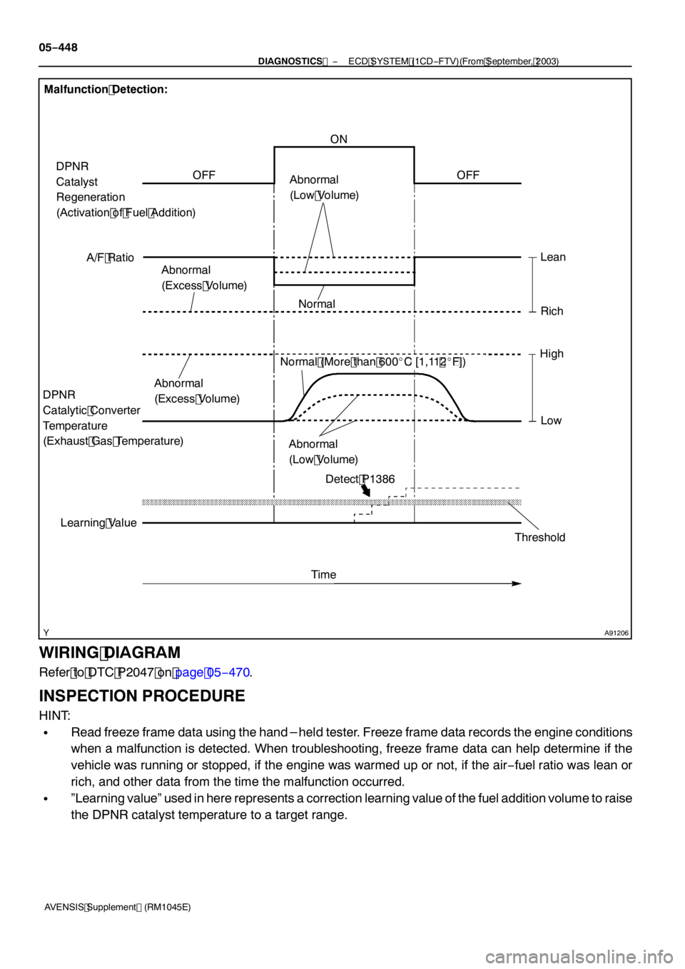
In order to detect malfunction in the exhaust fuel addition injector, the ECM monitors: the air−fuel ratio, DPNR
catalytic temperature and learning value.
SWhen the exhaust fuel addition injector adds fuel during NOx reduction, the ECM monitors the air−fuel
ratio when the exhaust fuel addition injector adds fuel. If the air−fuel ratio is too RICH or too LEAN
against the ECM predetermined air−fuel ratio, the ECM judges the fuel addition volume small or large,
and illuminates the CHK ENG. In this malfunction, there is no fail−safe operation.
SThe ECM always monitors the DPNR catalytic converter temperature and the air−fuel ratio. When the
temperature reaches higher than its usual level or the air−fuel ratio becomes extremely RICH, the ECM
judges that the injector has stuck open and illuminates the CHK ENG. If this malfunction occurs, the
ECM enters the fail−safe mode to limits its acceptable vehicle speed to approximately10 km/h (6 mph)
at maximum by restraining the engine power.
SUnder DPNR catalyst regeneration, the ECM monitors the learning value. Normally, the learning value
for the DPNR catalyst regeneration is in the vicinity of1.0. Thus the learning value is at1.4 or more
for a certain period of time, the ECM judges the fuel addition volume from the injector insufficient and
illuminates the CHK ENG. If this malfunction occurs, the ECM enters the fail−safe mode to limit its ac-
ceptable vehicle speed to approximately 80 km/h (50 mph) at maximum by restraining the engine pow-
er.
Malfunction Condition by Fail−Safe Operation:
Fail−Safe OperationMalfunction ConditionMalfunction Detection ConditionDrive Pattern
No fail−safe operation
Low or excess fuel
addition volume from
the exhaust fuel addi-
tion injectorWhen the exhaust fuel addition injector adds fuel during NOx
reduction, if actual air−fuel ratio deviates from a value esti-
mated by the ECM when the exhaust fuel addition injector
adds fuel
After engine warm−up, per-
form DPNR REJU (PM) in
the ACTIVE TEST menu us-
ing the hand−held tester,
and drive at constant vehicle
speed within 50 to100 km/h
(31to 62 mph) for more than
15 minutes
Limits engine power by
permitting driving at ve-
hicle speed of approxi-
mately10 km/h (6 mph)
at maximum
Exhaust fuel addition
injector has stuck
openDPNR catalytic converter temperature reaches higher than
800_C(1,472_F) or air−fuel ratio is less than approximately
12 for a couple of secondsIdling engine for more than 5
minutes (*5)
Limits engine power by
permitting driving at ve-
hicle speed of approxi-
mately 80 km/h (50 mph)
at maximum
(HINT: DPNR catalyst re-
generation is prohibited)
Low fuel addition vol-
ume from the exhaust
fuel addition injectorUnder DPNR catalyst regeneration, when learning value of
1.4 or more continues for a certain period of time (*6)
After engine warm−up, per-
form DPNR REJU (PM) in
the ACTIVE TEST menu us-
ing the hand−held tester,
and drive at constant vehicle
speed within 50 to100 km/h
(31to 62 mph) for more than
30 minutes
*5: The DPNR catalytic converter temperature will not reach 800_C(1,472_F) or higher during idling even
if the exhaust fuel addition injector has stuck open.
*6: While the DPNR catalyst regeneration is exercised, the ECM raises the DPNR catalytic converter temper-
ature to more than approximately 600_C(1,112_F) by adding fuel using the exhaust fuel addition injector.
If the temperature does not reach that temperature regardless of the attempt, the correction learning value
of the fuel addition volume increments to raise the DPNR catalytic converter temperature to a target range.
Page 4406 of 5135
A91206
Malfunction Detection:
Abnormal
(Low Volume)ON
OFF
Time
DPNR
Catalyst
Regeneration
(Activation of Fuel Addition)
Normal
A/F Ratio
Learning ValueLean
Rich
Abnormal
(Excess Volume)
Abnormal
(Low Volume)
Abnormal
(Excess Volume)
Threshold
OFF
HighLow
DPNR
Catalytic Converter
Temperature
(Exhaust Gas Temperature)
Normal (More than 600
_ C[ 1,11 2_ F])
Detect P 1386
05 −448
−
DIAGNOSTICS ECD SYSTEM (1CD −FTV)(From September, 2003)
AVENSIS Supplement (RM 1045E)
WIRING DIAGRAM
Refer to DTC P2047 on page 05 −470.
INSPECTION PROCEDURE
HINT:
SRead freeze frame data using the hand−held tester. Freeze frame data records the engine conditions
when a malfunction is detected. When troubleshooting, freeze frame data can help determine if the
vehicle was running or stopped, if the engine was warmed up or not, if the air −fuel ratio was lean or
rich, and other data from the time the malfunction occurred.
S”Learning value” used in here represents a correction learning value of the fuel addition volume to raise
the DPNR catalyst temperature to a target range.
Page 4413 of 5135

−
DIAGNOSTICS ECD SYSTEM (1CD −FTV)(From September, 2003)
05 −455
AVENSIS Supplement (RM 1045E)
B CHECK FOR INTERMITTENT PROBLEMS
(See page 05 −270)
A
1 5 REPLACE EXHAUST FUEL ADDITION INJECTOR ASSY (See page 14−1 66)
GO
16 PERFORM ACTIVE TEST USING HAND −HELD TESTER(DPNR CATALYST
REGENERATION)
(a) Clear the learning value by removing the negative battery cable for more than 1 minute.
(b) Connect the hand −held tester to the DLC3.
(c) Turn the ignition switch to ON and turn the hand −held tester ON.
(d) Select the item ”DIAGNOSIS / OBD/MOBD / ACTIVE TEST / DPNR REJU (PM)”.
(e) After warming up the engine, drive the vehicle at constant vehicle speed within 50 to 100 km/h (3 1 to
62 mph) (with smooth throttle operations) for more than 15 minutes.
(f) Select the item ”DIAGNOSIS / OBD/MOBD / DATA LIST / ALL / AF FT B 1 S1”.
(g) Select the item ”DIAGNOSIS / OBD/MOBD / DATA LIST / ALL / EX TEMP (IN) and EX TEMP (OUT)”.
(h) Select the item ”DIAGNOSIS / OBD/MOBD / DATA LIST / ALL / EX FUEL ADD FB”.
(i) Check that the exhaust gas temperatures (EX TEMP [IN] and [OUT]) and the learning value (EX FUEL ADD FB) are within the specification below.
Result:
ResultProceed to
Exhaust gas temperature does not reach higher than 600 _ C
( 1 ,11 2_ F)A
Exhaust gas temperature reaches higher than 600 _ C
( 1 ,11 2_F), and the learning value remains in the vicinity of
1 .0
B
B SYSTEM OK
A
REPLACE MANIFOLD CONVERTER SUB −ASSY (DPNR CATALYTIC CONVERTER)
(See page 14−1 08)