glove box TOYOTA AVENSIS 2005 Service Repair Manual
[x] Cancel search | Manufacturer: TOYOTA, Model Year: 2005, Model line: AVENSIS, Model: TOYOTA AVENSIS 2005Pages: 5135, PDF Size: 95.28 MB
Page 3096 of 5135
650T5±01
I35250
65±30
±
LIGHTING HEADLAMP LEVELING ECU ASSY
AVENSIS REPAIR MANUAL (RM1018E)
HEADLAMP LEVELING ECU ASSY
REPLACEMENT
1. REMOVE GLOVE COMPARTMENT DOOR ASSY (LHD STEERING POSITION TYPE) (See page 71±11)
2.REMOVE FUSE BOX OPENING COVER (RHD STEERING POSITION TYPE) (See page 71±11)
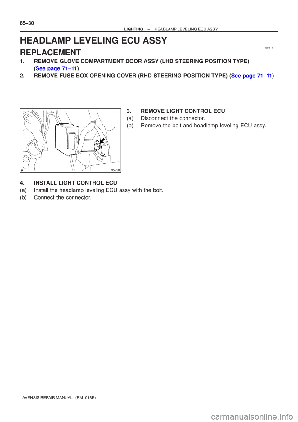
3. REMOVE LIGHT CONTROL ECU
(a) Disconnect the connector.
(b) Remove the bolt and headlamp leveling ECU assy.
4. INSTALL LIGHT CONTROL ECU
(a) Install the headlamp leveling ECU assy with the bolt.
(b) Connect the connector.
Page 3115 of 5135
E68137
E68137
65±12
± LIGHTINGLIGHTING SYSTEM
AVENSIS REPAIR MANUAL (RM1018E)
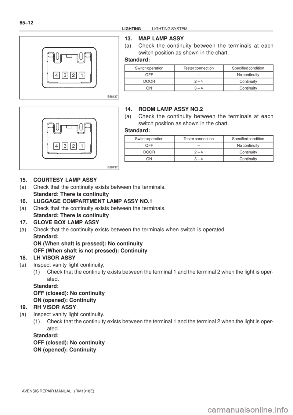
13. MAP LAMP ASSY
(a) Check the continuity between the terminals at each
switch position as shown in the chart.
Standard:
Switch operationTester connectionSpecified condition
OFF±No continuity
DOOR2 ± 4Continuity
ON3 ± 4Continuity
14. ROOM LAMP ASSY NO.2
(a) Check the continuity between the terminals at each
switch position as shown in the chart.
Standard:
Switch operationTester connectionSpecified condition
OFF±No continuity
DOOR2 ± 4Continuity
ON3 ± 4Continuity
15. COURTESY LAMP ASSY
(a) Check that the continuity exists between the terminals.
Standard: There is continuity
16. LUGGAGE COMPARTMENT LAMP ASSY NO.1
(a) Check that the continuity exists between the terminals.
Standard: There is continuity
17. GLOVE BOX LAMP ASSY
(a) Check that the continuity exists between the terminals when switch is operated.
Standard:
ON (When shaft is pressed): No continuity
OFF (When shaft is not pressed): Continuity
18. LH VISOR ASSY
(a) Inspect vanity light continuity.
(1) Check that the continuity exists between the terminal 1 and the terminal 2 when the light is oper-
ated.
Standard:
OFF (closed): No continuity
ON (opened): Continuity
19. RH VISOR ASSY
(a) Inspect vanity light continuity.
(1) Check that the continuity exists between the terminal 1 and the terminal 2 when the light is oper-
ated.
Standard:
OFF (closed): No continuity
ON (opened): Continuity
Page 3228 of 5135
B660325 Clips
71±18
±
INSTRUMENT PANEL/METER INSTRUMENT PANEL SUB±ASSY LOWER
AVENSIS REPAIR MANUAL (RM1018E)
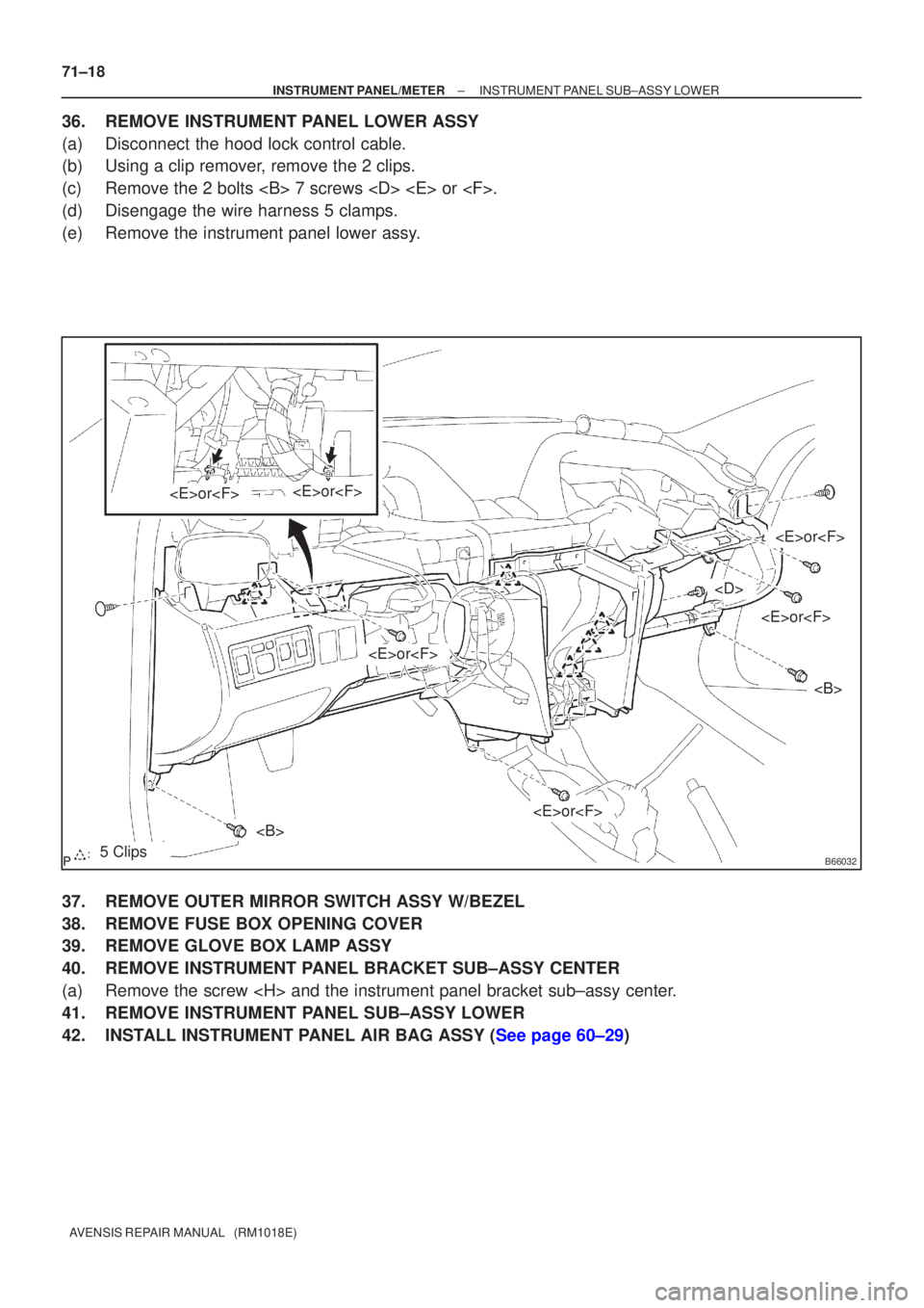
36.REMOVE INSTRUMENT PANEL LOWER ASSY
(a)Disconnect the hood lock control cable.
(b)Using a clip remover, remove the 2 clips.
(c)Remove the 2 bolts 7 screws
(d)Disengage the wire harness 5 clamps.
(e)Remove the instrument panel lower assy.
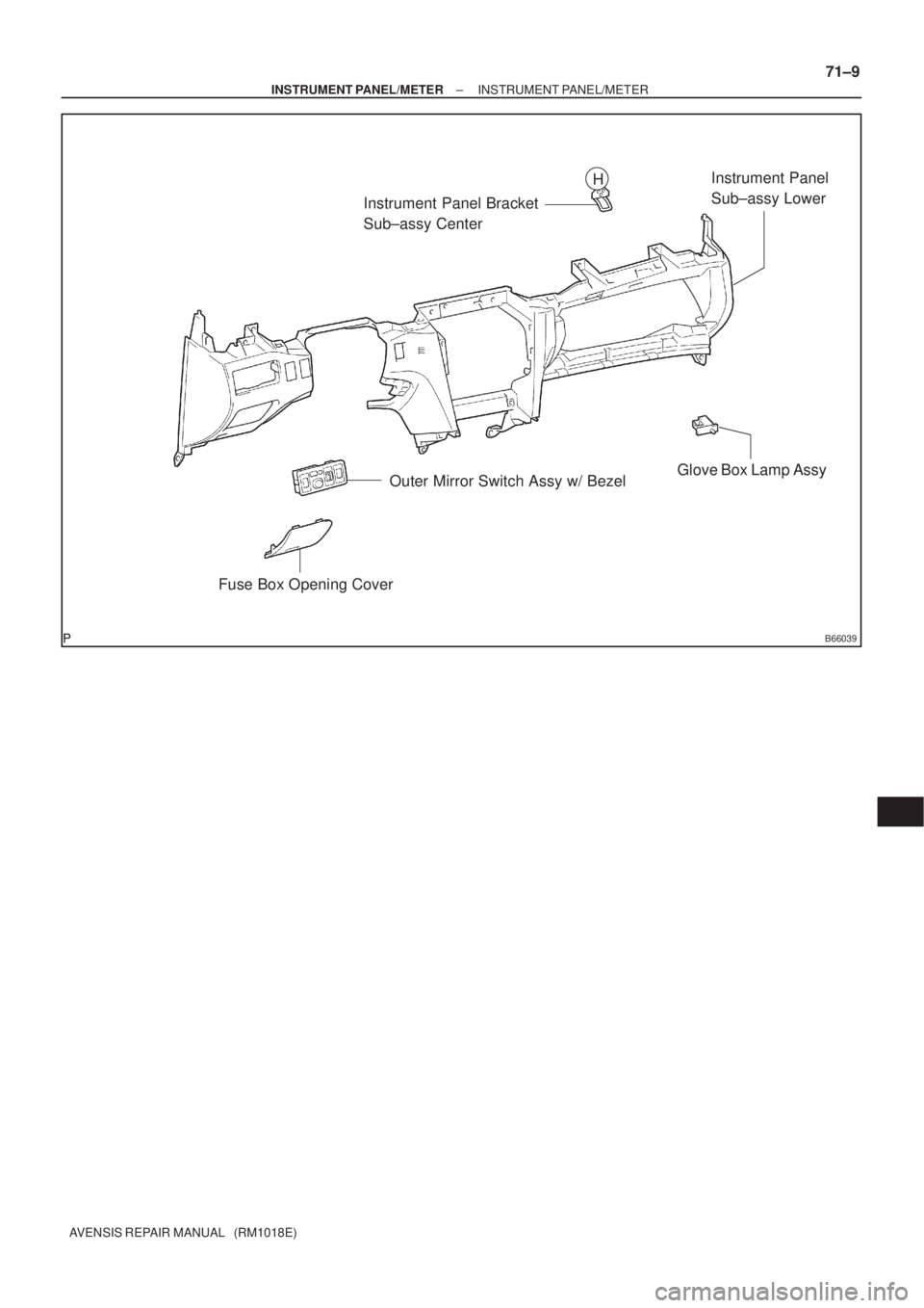
37.REMOVE OUTER MIRROR SWITCH ASSY W/BEZEL
38.REMOVE FUSE BOX OPENING COVER
39.REMOVE GLOVE BOX LAMP ASSY
40.REMOVE INSTRUMENT PANEL BRACKET SUB±ASSY CENTER
(a)Remove the screw
41.REMOVE INSTRUMENT PANEL SUB±ASSY LOWER
42.INSTALL INSTRUMENT PANEL AIR BAG ASSY (See page 60±29)
Page 3232 of 5135
710G2±01
B66037
Front Pillar Garnish LH
Front Pillar Garnish RH
Instrument Panel Register
Assy No.2
Instrument Panel Register
Assy No.1
Steering Column Cover
w/ Instrument Cluster Finish Panel AssyCombination Meter AssyGlove Compartment
Door AssyGlove Compartment
Door Stopper Sub±assy
w/ Multi±Display: w/ Box: w/ Navi:
Instrument Panel Register Assy CTR
Instrument Cluster Finish
Panel Garnish No.2 Steering
Column Cover LWR
Instrument Cluster Finish
Panel Garnish No.1
Combination Meter Glass
N´m (kgf´cm, ft´lbf) : Specified torque
A
G
H
H
HHHHHH
20 (200, 14)
± INSTRUMENT PANEL/METERINSTRUMENT PANEL/METER
71±7
AVENSIS REPAIR MANUAL (RM1018E)
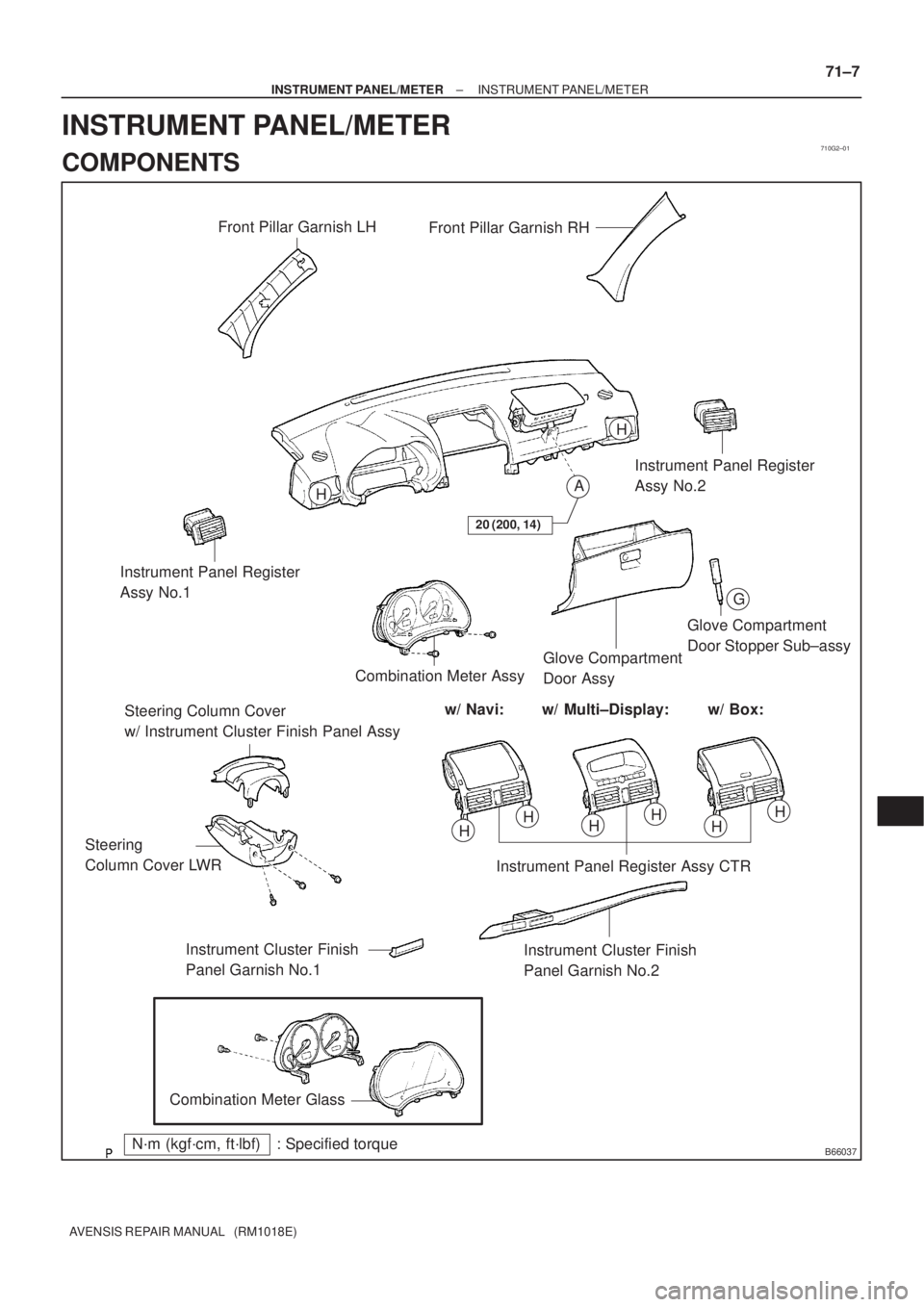
INSTRUMENT PANEL/METER
COMPONENTS
Page 3234 of 5135
B66039
Instrument Panel Bracket
Sub±assy CenterInstrument Panel
Sub±assy Lower
Glove Box Lamp Assy
Outer Mirror Switch Assy w/ Bezel
Fuse Box Opening Cover
H
± INSTRUMENT PANEL/METERINSTRUMENT PANEL/METER
71±9
AVENSIS REPAIR MANUAL (RM1018E)
Page 5097 of 5135
B66033
B660325 Clamps
– INSTRUMENT PANEL/METERINSTRUMENT PANEL SUB–ASSY LOWER (From
February, 2004)
AVENSIS REPAIR MANUAL SUPPLEMENT
(RM1098E)
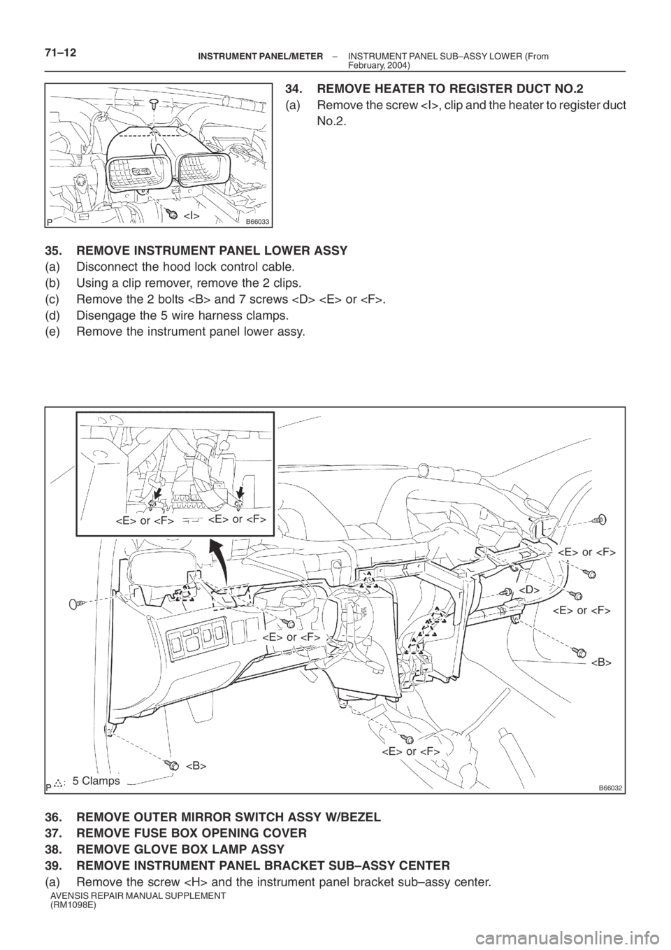
34. REMOVE HEATER TO REGISTER DUCT NO.2
(a) Remove the screw , clip and the heater to register duct
No.2.
35. REMOVE INSTRUMENT PANEL LOWER ASSY
(a) Disconnect the hood lock control cable.
(b) Using a clip remover, remove the 2 clips.
(c) Remove the 2 bolts and 7 screws
(d) Disengage the 5 wire harness clamps.
(e) Remove the instrument panel lower assy.
36. REMOVE OUTER MIRROR SWITCH ASSY W/BEZEL
37. REMOVE FUSE BOX OPENING COVER
38. REMOVE GLOVE BOX LAMP ASSY
39. REMOVE INSTRUMENT PANEL BRACKET SUB–ASSY CENTER
(a) Remove the screw