check engine TOYOTA AYGO 2017 Owners Manual (in English)
[x] Cancel search | Manufacturer: TOYOTA, Model Year: 2017, Model line: AYGO, Model: TOYOTA AYGO 2017Pages: 480, PDF Size: 40.72 MB
Page 4 of 480
TABLE OF CONTENTS4
AYGO_OM_Europe_OM99Q24E
5-8. Bluetooth® Phone
Making a phone call ...........278
Receiving a phone call.......280
Speaking on the phone ......281
5-9. Bluetooth®
Bluetooth®.........................283
6-1. Using the air conditioning
system and defogger
Manual air conditioning
system .............................290
Automatic air conditioning
system .............................296
Seat heaters ......................302
6-2. Using the interior lights
Interior lights list .................304
• Interior light ....................304
6-3. Using the storage features
List of storage features ......305
• Glove box ......................306
• Card holders ..................306
• Cup holders ...................306
• Bottle holders ................307
Luggage compartment
features............................309
6-4. Other interior features
Other interior features ........311
• Sun visors ......................311
• Vanity mirrors ................311
• Clock .............................312
• Outside temperature
display ...........................313
• Power outlet ..................314
7-1. Maintenance and care
Cleaning and protecting
the vehicle exterior .......... 316
Cleaning and protecting
the vehicle interior ........... 320
7-2. Maintenance
Maintenance
requirements ................... 323
7-3. Do-it-yourself maintenance
Do-it-yourself service
precautions ..................... 325
Hood.................................. 328
Positioning a floor jack ...... 330
Engine compartment ......... 331
Tires .................................. 343
Tire inflation pressure........ 349
Wheels .............................. 351
Air conditioning filter .......... 353
Wireless remote control/
electronic key battery ...... 354
Checking and replacing
fuses ............................... 357
Light bulbs ......................... 365
6Interior features
7Maintenance and care
Page 11 of 480
11Pictorial index
AYGO_OM_Europe_OM99Q24E
Windshield wiper . . . . . . . . . . . . . . . . . . . . . . . . . . . . . . . . . . P. 178
Precautions against winter season . . . . . . . . . . . . . . . . . . . . . P. 229
Fuel filler door . . . . . . . . . . . . . . . . . . . . . . . . . . . . . . . . . . . . P. 182
Refueling method . . . . . . . . . . . . . . . . . . . . . . . . . . . . . . . . . . P. 182
Fuel type/fuel tank capacity . . . . . . . . . . . . . . . . . . . . . . . . . . . P. 446
Tires . . . . . . . . . . . . . . . . . . . . . . . . . . . . . . . . . . . . . . . . . . . . P. 343
Tire size/inflation pressure . . . . . . . . . . . . . . . . . . . . . . . . . . . . P. 454
Winter tires/tire chain . . . . . . . . . . . . . . . . . . . . . . . . . . . . . . . . P. 229
Checking/rotation/tire pressure warning system*2 . . . . . . . . . P. 343
Coping with flat tires . . . . . . . . . . . . . . . . . . . . . . . . . . . . P. 399, 412
Hood . . . . . . . . . . . . . . . . . . . . . . . . . . . . . . . . . . . . . . . . . . . . P. 328
Opening . . . . . . . . . . . . . . . . . . . . . . . . . . . . . . . . . . . . . . . . . . P. 328
Engine oil . . . . . . . . . . . . . . . . . . . . . . . . . . . . . . . . . . . . . . . . . P. 446
Coping with overheat . . . . . . . . . . . . . . . . . . . . . . . . . . . . . . . . P. 436
Camera*2, 3
Headlights . . . . . . . . . . . . . . . . . . . . . . . . . . . . . . . . . . . . . . . P. 172
Front position lights . . . . . . . . . . . . . . . . . . . . . . . . . . . . . . . P. 172
Daytime running lights*2 . . . . . . . . . . . . . . . . . . . . . . . . . . . P. 172
Front fog lights*2/rear fog lights . . . . . . . . . . . . . . . . . . . . . P. 176
Turn signal lights . . . . . . . . . . . . . . . . . . . . . . . . . . . . . . . . . . P. 170
Emergency brake signal . . . . . . . . . . . . . . . . . . . . . . . . . . . . . P. 223
Tail lights . . . . . . . . . . . . . . . . . . . . . . . . . . . . . . . . . . . . . . . . P. 172
License plate lights . . . . . . . . . . . . . . . . . . . . . . . . . . . . . . . . P. 172
Back-up lights
Shifting the shift lever to R. . . . . . . . . . . . . . . . . . . . . . . . P. 163, 168
4
5
6
7
8
Light bulbs of the exterior lights for driving
(Replacing method: P. 365, Watts: P. 456)
*1: Vehicles with a smart entry & start system
*2: If equipped
*3: For vehicles with a multimedia system , refer to “Multimedia owner’s manual”.
9
10
11
12
13
14
15
16
Page 27 of 480
271-1. For safe use
1
For safety and security
AYGO_OM_Europe_OM99Q24E
WARNING
Observe the following precautions.
Failure to do so may cause the driver’s floor mat to slip, possibly interfering
with the pedals while driving. An unexpectedly high speed may result or it may
become difficult to stop the vehicle. This could lead to an accident, resulting in
death or serious injury.
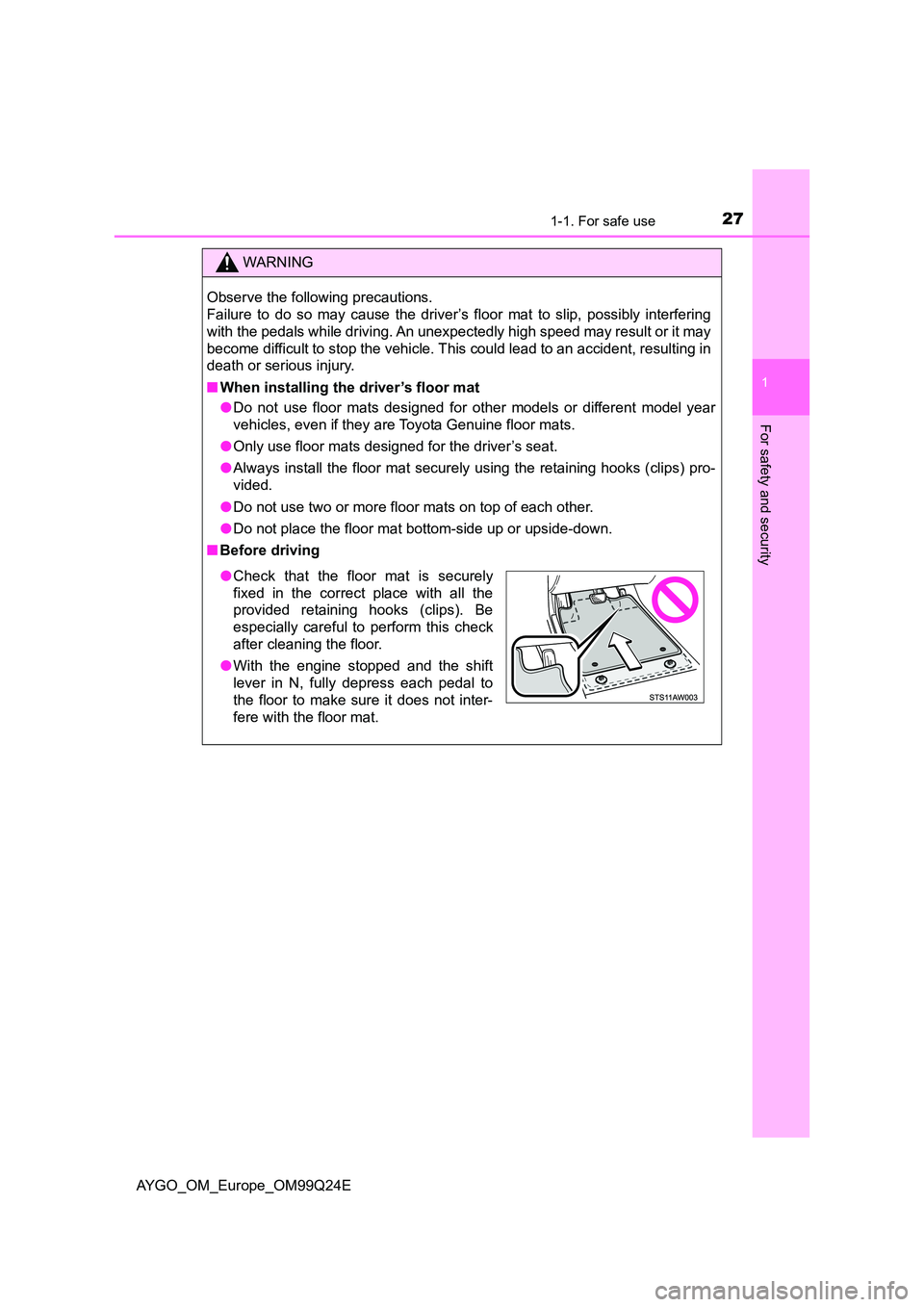
■ When installing the driver’s floor mat
● Do not use floor mats designed for other models or different model year
vehicles, even if they are Toyota Genuine floor mats.
● Only use floor mats designed for the driver’s seat.
● Always install the floor mat securely using the retaining hooks (clips) pro-
vided.
● Do not use two or more floor mats on top of each other.
● Do not place the floor mat bottom-side up or upside-down.
■ Before driving
●Check that the floor mat is securely
fixed in the correct place with all the
provided retaining hooks (clips). Be
especially careful to perform this check
after cleaning the floor.
● With the engine stopped and the shift
lever in N, fully depress each pedal to
the floor to make sure it does not inter-
fere with the floor mat.
Page 46 of 480
461-1. For safe use
AYGO_OM_Europe_OM99Q24E
Exhaust gas precautions
Harmful substance to the human body is included in exhaust
gases if inhale.
WARNING
Exhaust gases include harmful carbon monoxide (CO), which is colorless and
odorless. Observe the following precautions.
Failure to do so may cause exhaust gases enter the vehicle and may lead to
an accident caused by light-headedness, or may lead to death or a serious
health hazard.
■ Important points while driving
● Keep the back door closed.
● If you smell exhaust gases in the vehicle even when the back door is
closed, open the windows and have the vehicle inspected at any autho-
rized Toyota dealer or repairer, or another duly qualified and equipped pro-
fessional as soon as possible.
■ When parking
● If the vehicle is in a poorly ventilated area or a closed area, such as a
garage, stop the engine.
● Do not leave the vehicle with the engine running for a long time.
If such a situation cannot be avoided, park the vehicle in an open space
and ensure that exhaust fumes do not enter the vehicle interior.
● Do not leave the engine running in an area with snow build-up, or where it
is snowing. If snowbanks build up around the vehicle while the engine is
running, exhaust gases may collect and enter the vehicle.
■ Exhaust pipe
The exhaust system needs to be checked periodically. If there is a hole or
crack caused by corrosion, damage to a joint or abnormal exhaust noise, be
sure to have the vehicle inspected and repaired by any authorized Toyota
dealer or repairer, or another duly qualified and equipped professional.
Page 86 of 480
862. Instrument cluster
AYGO_OM_Europe_OM99Q24E
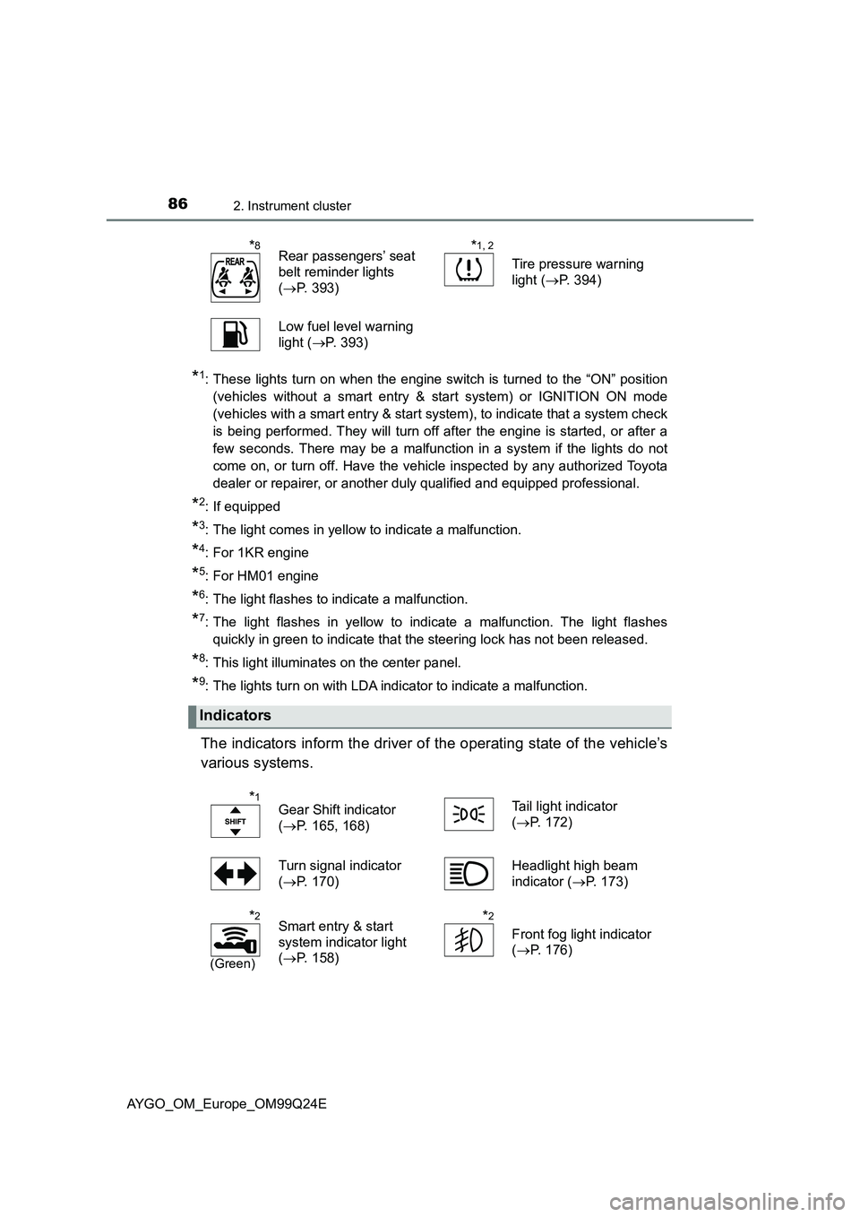
*1: These lights turn on when the engine switch is turned to the “ON” position
(vehicles without a smart entry & start system) or IGNITION ON mode
(vehicles with a smart entry & start system), to indicate that a system check
is being performed. They will turn off after the engine is started, or after a
few seconds. There may be a malfunction in a system if the lights do not
come on, or turn off. Have the vehicle inspected by any authorized Toyota
dealer or repairer, or another duly qualified and equipped professional.
*2: If equipped
*3: The light comes in yellow to indicate a malfunction.
*4: For 1KR engine
*5: For HM01 engine
*6: The light flashes to indicate a malfunction.
*7: The light flashes in yellow to indicate a malfunction. The light flashes
quickly in green to indicate that the steering lock has not been released.
*8: This light illuminates on the center panel.
*9: The lights turn on with LDA indicator to indicate a malfunction.
The indicators inform the driver of the operating state of the vehicle’s
various systems.
*8Rear passengers’ seat
belt reminder lights
( P. 393)
*1, 2
Tire pressure warning
light ( P. 394)
Low fuel level warning
light ( P. 393)
Indicators
*1Gear Shift indicator
( P. 165, 168)
Tail light indicator
( P. 172)
Turn signal indicator
( P. 170)
Headlight high beam
indicator ( P. 173)
*2
(Green)
Smart entry & start
system indicator light
( P. 158)
*2
Front fog light indicator
( P. 176)
Page 87 of 480
872. Instrument cluster
2
Instrument cluster
AYGO_OM_Europe_OM99Q24E
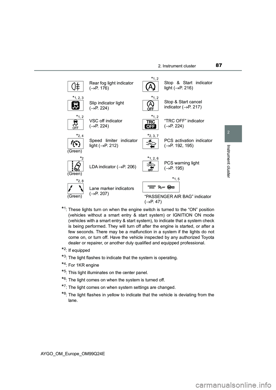
*1: These lights turn on when the engine switch is turned to the “ON” position
(vehicles without a smart entry & start system) or IGNITION ON mode
(vehicles with a smart entry & start system), to indicate that a system check
is being performed. They will turn off after the engine is started, or after a
few seconds. There may be a malfunction in a system if the lights do not
come on, or turn off. Have the vehicle inspected by any authorized Toyota
dealer or repairer, or another duly qualified and equipped professional.
*2: If equipped
*3: The light flashes to indicate that the system is operating.
*4: For 1KR engine
*5: This light illuminates on the center panel.
*6: The light comes on when the system is turned off.
*7: The light comes on when system settings are changed.
*8: The light flashes in yellow to indicate that the vehicle is deviating from the
lane.
Rear fog light indicator
( P. 176)
*1, 2Stop & Start indicator
light ( P. 216)
*1, 2, 3
Slip indicator light
( P. 224)
*1, 2Stop & Start cancel
indicator ( P. 217)
*1, 2VSC off indicator
( P. 224)
*1, 2“TRC OFF” indicator
( P. 224)
*2, 4
(Green)
Speed limiter indicator
light ( P. 212)
*2, 3, 7
PCS activation indicator
( P. 192, 195)
*2
(Green)
LDA indicator (P. 206)
*1, 2, 6
PCS warning light
( P. 195)
*2, 8
(Green)
Lane marker indicators
( P. 207) “PASSENGER AIR BAG” indicator
( P. 4 7 )
*1, 5
Page 88 of 480
882. Instrument cluster
AYGO_OM_Europe_OM99Q24E
WARNING
■If a safety system warning light does not come on
Should a safety system light such as the ABS and SRS warning light not
come on when you start the engine, this could mean that these systems are
not available to help protect you in an accident, which could result in death
or serious injury. Have the vehicle inspected by any authorized Toyota
dealer or repairer, or another duly qualified and equipped professional
immediately if this occurs.
NOTICE
■ To prevent damage to the engine and its components
The engine may be overheating if the high engine coolant temperature
warning light flashes or turns on. In this case, immediately stop the vehicle
in a safe place, and check the engine after it has cooled completely.
( P. 4 3 6 )
Page 122 of 480
1223-2. Opening, closing and locking the doors
AYGO_OM_Europe_OM99Q24E
■ Note for the entry function
● Even when the electronic key is within the effective range (detection areas),
the system may not operate properly in the following cases:
• The electronic key is too close to the window or outside door handle, near
the ground, or in a high place w hen the doors are locked or unlocked.
• The electronic key is on the instrument panel, luggage cover (if equipped)
or floor, or in the door pockets or glove box when the engine is started or
engine switch modes are changed.
● As long as the electronic key is within the effective range, the doors may be
locked or unlocked by anyone. However, only the doors detecting the elec-
tronic key can be used to unlock the vehicle.
Depending on the situation, even when the electronic key in the vicinity of
opposite side door to the door to be unlocked, the electronic key may be
detected and the door unlocks.
● If the wireless remote control is used to lock the doors when the electronic
key is near the vehicle, there is a possibility that the door may not be
unlocked by the entry function. (Use the wireless remote control to unlock
the doors.)
■ Note for the unlocking function
● There are cases when pulling the door handle while pressing the Lock/
Unlock button that the door will not unlock. In those cases, after returning
the door handle to the original position, press the Lock/Unlock button once
again and check that the doors unlock before pulling the door handle.
● If there is another electronic key in the detection area, it may take slightly
longer for the doors to unlock after the Lock/Unlock button is pressed.
■ When the vehicle is not driven for extended periods
● To prevent theft of the vehicle, do not leave the electronic key within 2 m
(6 ft.) of the vehicle.
● The smart entry & start system can be deactivated in advance. (P. 459)
■ To operate the system properly
Make sure to carry the electronic key when operating the system. Do not get
the electronic key too close to the vehicle when operating the system from the
outside of the vehicle.
Depending on the position and holding condition of the electronic key, the key
may not be detected correctly and the system may not operate properly. (The
alarm may go off accidentally, or the door lock prevention function may not
operate.)
■ If the smart entry & start system does not operate properly
● Locking and unlocking the doors: Use the mechanical key. (P. 429)
● Starting the engine: P. 430
Page 137 of 480
137
3
3-5. Opening, closing the windows and canvas top
Operation of each component
AYGO_OM_Europe_OM99Q24E
Power windows
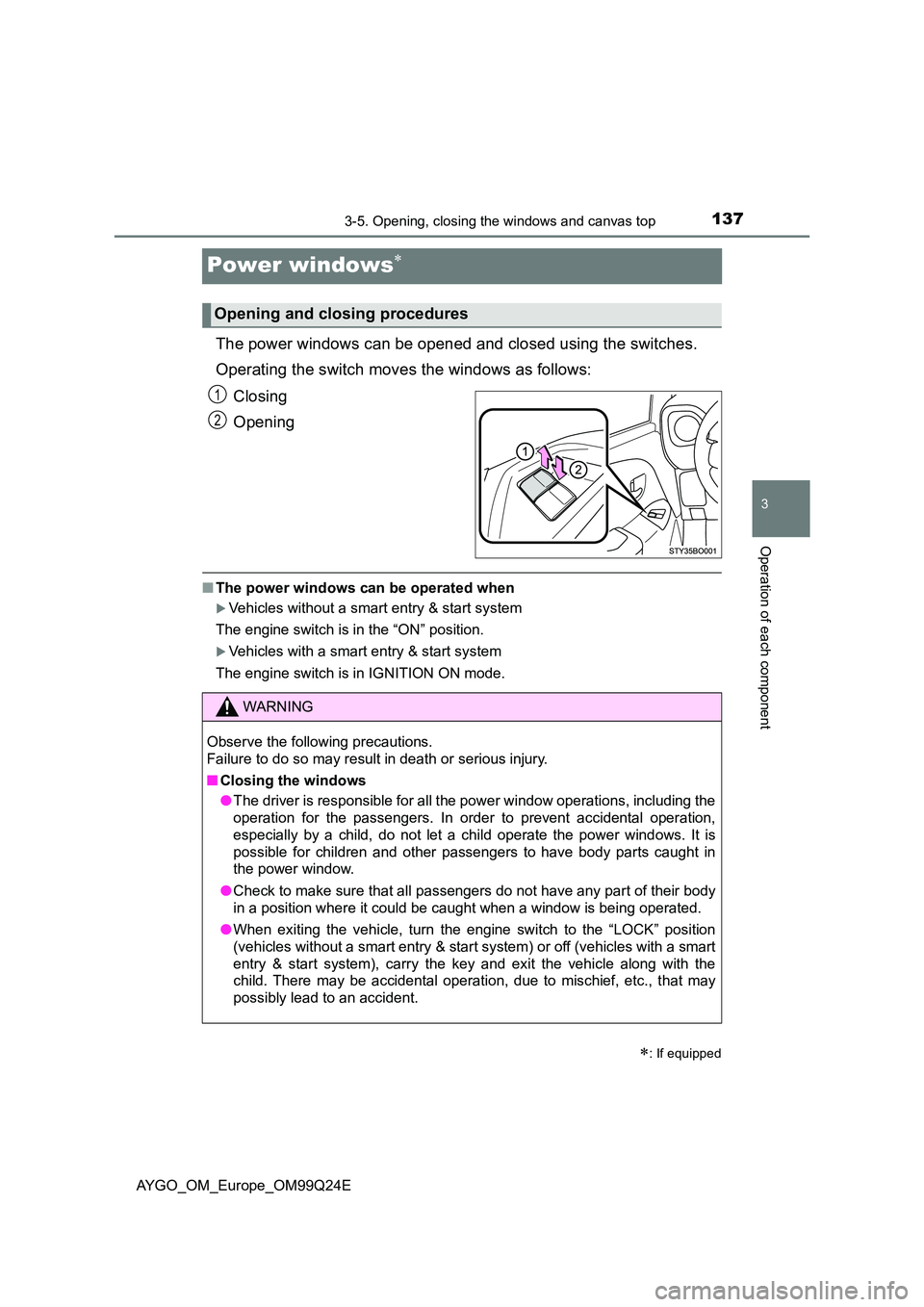
The power windows can be opened and closed using the switches.
Operating the switch moves the windows as follows:
Closing
Opening
■ The power windows can be operated when
Vehicles without a smart entry & start system
The engine switch is in the “ON” position.
Vehicles with a smart entry & start system
The engine switch is in IGNITION ON mode.
: If equipped
Opening and closing procedures
1
2
WARNING
Observe the following precautions.
Failure to do so may result in death or serious injury.
■ Closing the windows
● The driver is responsible for all the power window operations, including the
operation for the passengers. In order to prevent accidental operation,
especially by a child, do not let a child operate the power windows. It is
possible for children and other passengers to have body parts caught in
the power window.
● Check to make sure that all passengers do not have any part of their body
in a position where it could be caught when a window is being operated.
● When exiting the vehicle, turn the engine switch to the “LOCK” position
(vehicles without a smart entry & start system) or off (vehicles with a smart
entry & start system), carry the key and exit the vehicle along with the
child. There may be accidental operation, due to mischief, etc., that may
possibly lead to an accident.
Page 140 of 480
1403-5. Opening, closing the windows and canvas top
AYGO_OM_Europe_OM99Q24E
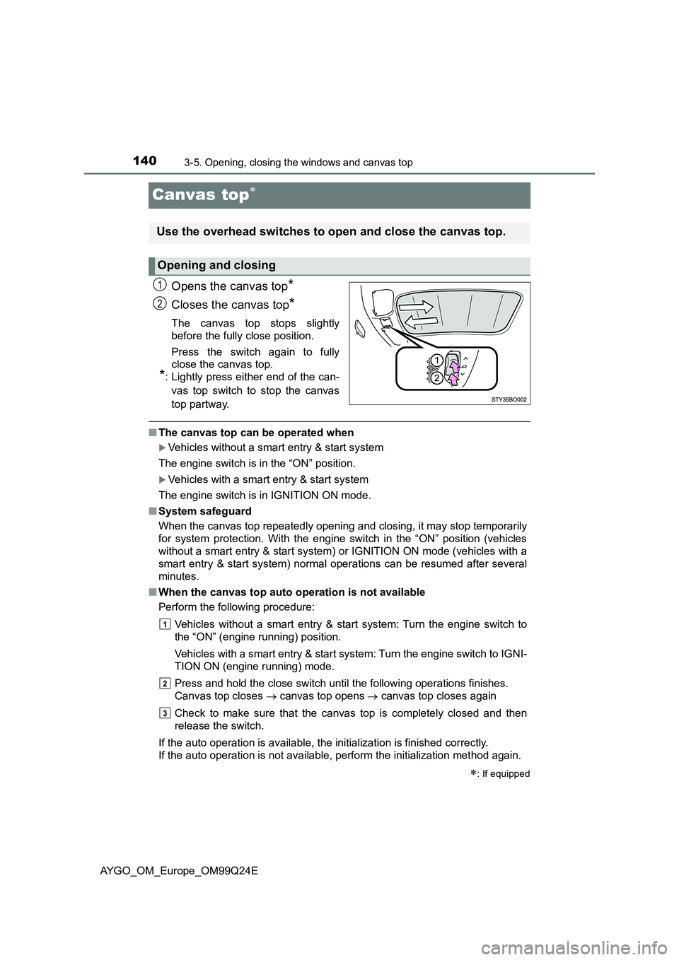
Canvas top
Opens the canvas top*
Closes the canvas top*
The canvas top stops slightly
before the fully close position.
Press the switch again to fully
close the canvas top.
*: Lightly press either end of the can-
vas top switch to stop the canvas
top partway.
■ The canvas top can be operated when
Vehicles without a smart entry & start system
The engine switch is in the “ON” position.
Vehicles with a smart entry & start system
The engine switch is in IGNITION ON mode.
■ System safeguard
When the canvas top repeatedly opening and closing, it may stop temporarily
for system protection. With the engine switch in the “ON” position (vehicles
without a smart entry & start system) or IGNITION ON mode (vehicles with a
smart entry & start system) normal operations can be resumed after several
minutes.
■ When the canvas top auto operation is not available
Perform the following procedure:
Vehicles without a smart entry & start system: Turn the engine switch to
the “ON” (engine running) position.
Vehicles with a smart entry & start system: Turn the engine switch to IGNI-
TION ON (engine running) mode.
Press and hold the close switch until the following operations finishes.
Canvas top closes canvas top opens canvas top closes again
Check to make sure that the canvas top is completely closed and then
release the switch.
If the auto operation is available, the initialization is finished correctly.
If the auto operation is not available, perform the initialization method again.
: If equipped
Use the overhead switches to open and close the canvas top.
Opening and closing
1
2