CAN TOYOTA BZ4X 2022 (in English) Owner's Manual
[x] Cancel search | Manufacturer: TOYOTA, Model Year: 2022, Model line: BZ4X, Model: TOYOTA BZ4X 2022Pages: 674, PDF Size: 120.02 MB
Page 52 of 674
50
Owners Manual_Europe_M42D76_en
1-2. Child safety
■When installing a child
restraint system to the front
passenger seat
For the safety of a child, install a
child restraint system to a rear seat.
When installing a child restraint
system to the front passenger seat
is unavoidable, adjust the seat as
follows and install the child restraint
system:
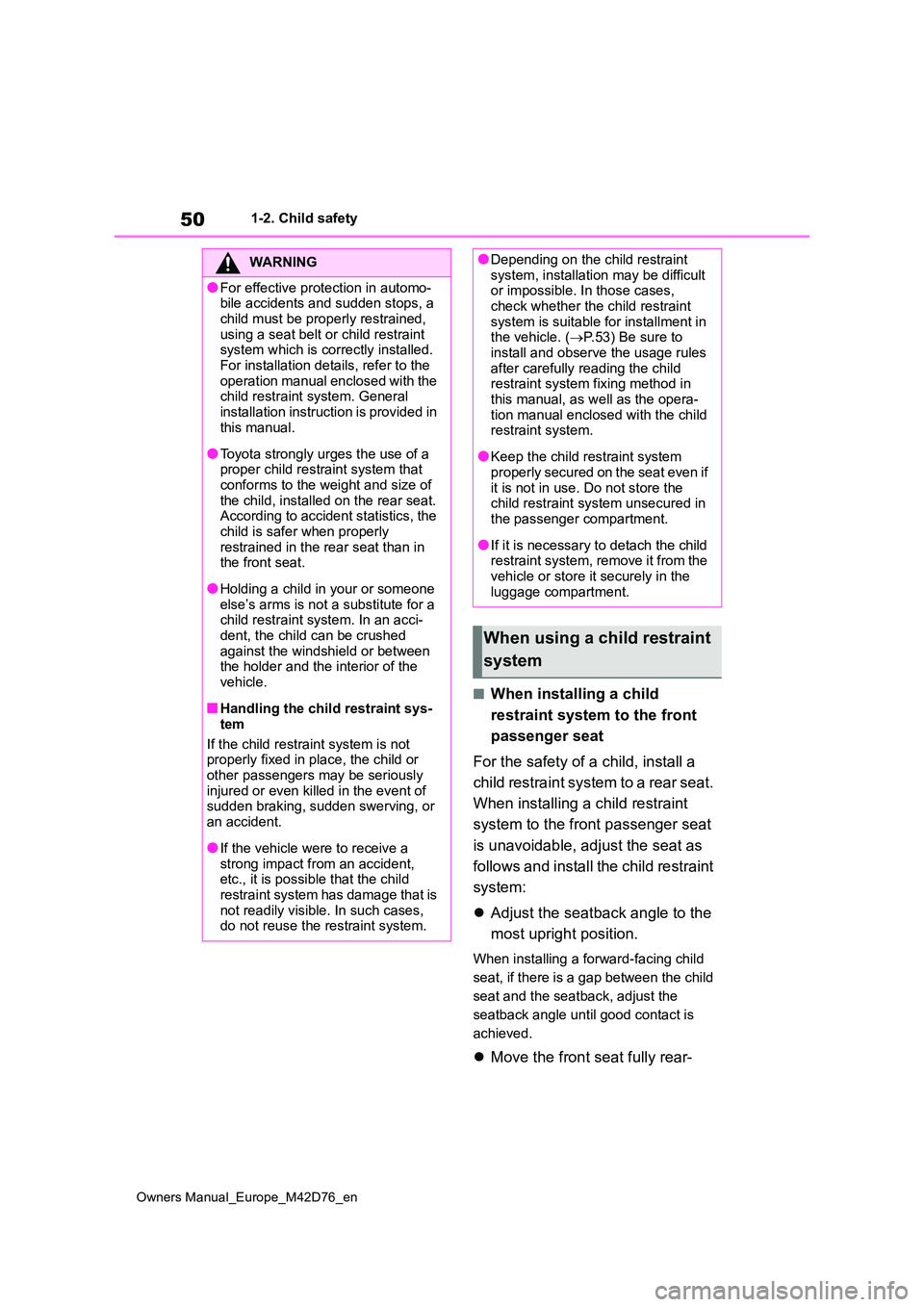
Adjust the seatback angle to the
most upright position.
When installing a forward-facing child
seat, if there is a gap between the child
seat and the seatback, adjust the
seatback angle until good contact is
achieved.
Move the front seat fully rear-
WARNING
●For effective protection in automo- bile accidents and sudden stops, a
child must be properly restrained, using a seat belt or child restraint system which is correctly installed.
For installation details, refer to the operation manual enclosed with the child restraint system. General
installation instruction is provided in this manual.
●Toyota strongly urges the use of a proper child restraint system that conforms to the weight and size of
the child, installed on the rear seat. According to accident statistics, the child is safer when properly
restrained in the rear seat than in the front seat.
●Holding a child in your or someone else’s arms is not a substitute for a child restraint system. In an acci-
dent, the child can be crushed against the windshield or between the holder and the interior of the
vehicle.
■Handling the child restraint sys-
tem
If the child restraint system is not properly fixed in place, the child or
other passengers may be seriously injured or even killed in the event of sudden braking, sudden swerving, or
an accident.
●If the vehicle were to receive a
strong impact from an accident, etc., it is possible that the child restraint system has damage that is
not readily visible. In such cases, do not reuse the restraint system.
●Depending on the child restraint system, installation may be difficult or impossible. In those cases,
check whether the child restraint system is suitable for installment in the vehicle. ( P.53) Be sure to
install and observe the usage rules after carefully reading the child restraint system fixing method in
this manual, as well as the opera- tion manual enclosed with the child restraint system.
●Keep the child restraint system properly secured on the seat even if
it is not in use. Do not store the child restraint system unsecured in the passenger compartment.
●If it is necessary to detach the child restraint system, remove it from the
vehicle or store it securely in the luggage compartment.
When using a child restraint
system
Page 53 of 674
51
1
Owners Manual_Europe_M42D76_en
1-2. Child safety
For safety and security
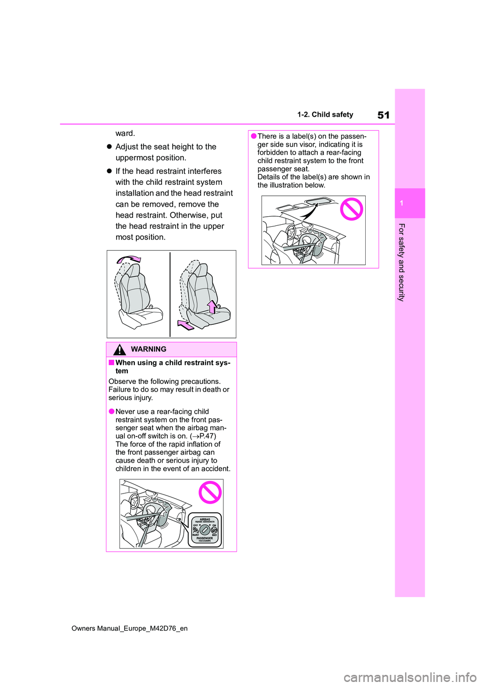
ward.
Adjust the seat height to the
uppermost position.
If the head restraint interferes
with the child restraint system
installation and the head restraint
can be removed, remove the
head restraint. Otherwise, put
the head restraint in the upper
most position.
WARNING
■When using a child restraint sys-
tem
Observe the following precautions. Failure to do so may result in death or
serious injury.
●Never use a rear-facing child
restraint system on the front pas- senger seat when the airbag man-ual on-off switch is on. ( P. 4 7 )
The force of the rapid inflation of the front passenger airbag can cause death or serious injury to
children in the event of an accident.
●There is a label(s) on the passen- ger side sun visor, indicating it is forbidden to attach a rear-facing
child restraint system to the front passenger seat.Details of the label(s) are shown in
the illustration below.
Page 55 of 674
53
1
Owners Manual_Europe_M42D76_en
1-2. Child safety
For safety and security
■Child restraint system compat-
ibility for each seating posi-
tion
Compatibility of each seating posi-
tion with child restraint systems
( P.54) displays the type of child
restraint systems that can be used
and possible seating positions for
installation using symbols.
Also, the recommended child
restraint system that is suitable for
your child can be selected. Other-
wise, check [Recommended child
restraint systems information] for
recommended child restraint sys-
tems. ( P. 5 8 )
Check the selected child restraint
system together with the following
[Before confirming the compatibility
of each seating position with child
restraint systems].
■Before confirming the compat-
ibility of each seating position
with child restraint systems
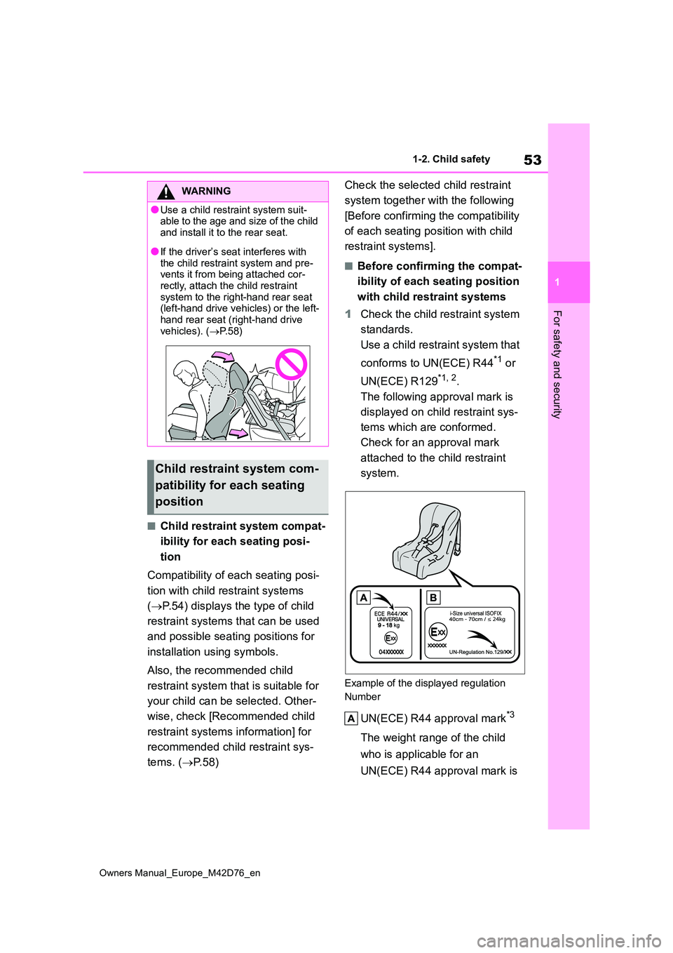
1 Check the child restraint system
standards.
Use a child restraint system that
conforms to UN(ECE) R44*1 or
UN(ECE) R129*1, 2.
The following approval mark is
displayed on child restraint sys-
tems which are conformed.
Check for an approval mark
attached to the child restraint
system.
Example of the displayed regulation
Number
UN(ECE) R44 approval mark*3
The weight range of the child
who is applicable for an
UN(ECE) R44 approval mark is
WARNING
●Use a child restraint system suit- able to the age and size of the child
and install it to the rear seat.
●If the driver’s seat interferes with
the child restraint system and pre- vents it from being attached cor-rectly, attach the child restraint
system to the right-hand rear seat (left-hand drive vehicles) or the left-hand rear seat (right-hand drive
vehicles). ( P. 5 8 )
Child restraint system com-
patibility for each seating
position
Page 57 of 674
55
1
Owners Manual_Europe_M42D76_en
1-2. Child safety
For safety and security
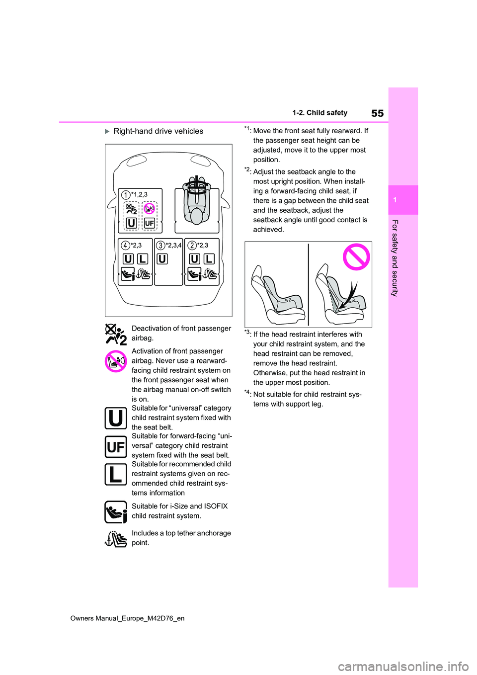
Right-hand drive vehicles*1: Move the front seat fully rearward. If
the passenger seat height can be
adjusted, move it to the upper most
position.
*2: Adjust the seatback angle to the
most upright position. When install-
ing a forward-facing child seat, if
there is a gap between the child seat
and the seatback, adjust the
seatback angle until good contact is
achieved.
*3: If the head restraint interferes with
your child restraint system, and the
head restraint can be removed,
remove the head restraint.
Otherwise, put the head restraint in
the upper most position.
*4: Not suitable for child restraint sys-
tems with support leg.
Deactivation of front passenger
airbag.
Activation of front passenger
airbag. Never use a rearward-
facing child restraint system on
the front passenger seat when
the airbag manual on-off switch
is on.
Suitable for “universal” category
child restraint system fixed with
the seat belt.
Suitable for forward-facing “uni-
versal” category child restraint
system fixed with the seat belt.
Suitable for recommended child
restraint systems given on rec-
ommended child restraint sys-
tems information
Suitable for i-Size and ISOFIX
child restraint system.
Includes a top tether anchorage
point.
Page 58 of 674

56
Owners Manual_Europe_M42D76_en
1-2. Child safety
■Detail information for child restraint systems installation
*1: All universal categories (group 0, 0+, I, II and III).
*2: Not suitable for child restraint systems with support leg.
Toyota suggests the users to use and seating positions.
ISOFIX child restraint systems are divided into different “fixt ure”. The child
restraint system can be used in the seating positions for “fixt ure” mentioned
in the table above. For kind of “ fixture” relation, confirm the following table.
If your child restraint system ha s no kind of “fixture” (or if you cannot find
information in the table below), please refer to the child rest raint system
“vehicle list” for compatibility information or ask the retaile r of your child
seat.
Seating position
Seat position number*2
Airbag manual on-
off switch
ONOFF
Seating position suitable for
universal belted (Yes/No)*1
Ye s
Forward-
facing
only
Ye sYe sYe sYe s
i-Size seating position
(Yes/No)NoNoYe sNoYe s
Seating position suitable for
lateral fixture (L1/L2/No)NoNoNoNoNo
Suitable rearward facing fix-
ture (R1/R2X/R2/R3/No)NoNoR1, R2X,
R2, R3NoR1, R2X,
R2, R3
Suitable forward facing fix-
ture (F2X/F2/F3/No)NoNoF2X, F2,
F3NoF2X, F2,
F3
Suitable junior seat fixture
(B2/B3/No)NoNoB2, B3NoB2, B3
Page 63 of 674
61
1
Owners Manual_Europe_M42D76_en
1-2. Child safety
For safety and security
1If installing the child restraint
system to the front passenger
seat is unavoidable, refer to
P.50 for front passenger seat
adjustment.
2 Adjust the seatback angle to the
most upright position. When
installing a forward-facing child
seat, if there is a gap between
the child seat and the seatback,
adjust the seatback angle until
good contact is achieved.
3 If the head restraint interferes
with the child restraint system
and the head restraint can be
removed, remove the head
restraint. Otherwise, put the
head restraint in the upper most
position. ( P. 2 1 1 )
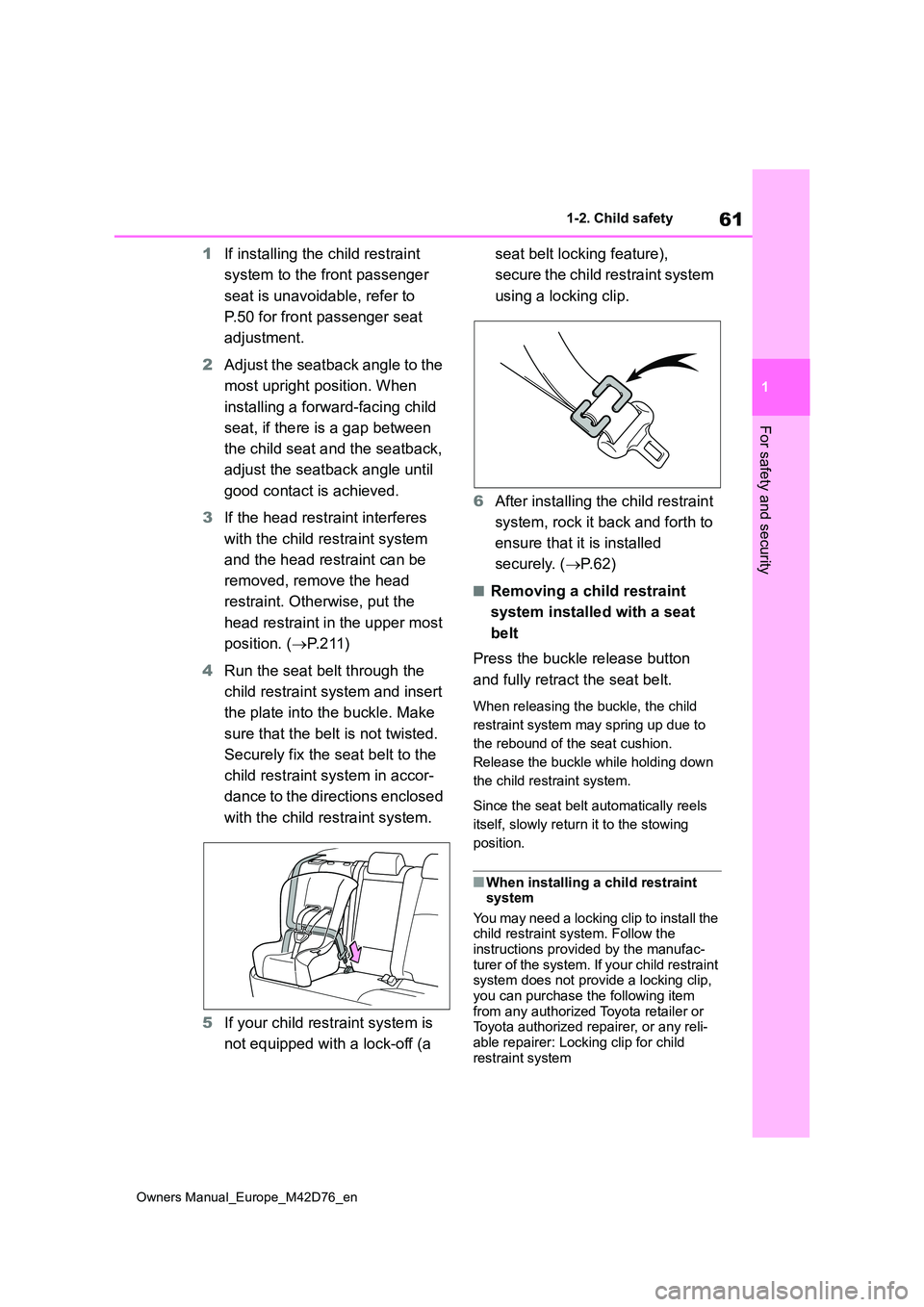
4 Run the seat belt through the
child restraint system and insert
the plate into the buckle. Make
sure that the belt is not twisted.
Securely fix the seat belt to the
child restraint system in accor-
dance to the directions enclosed
with the child restraint system.
5 If your child restraint system is
not equipped with a lock-off (a
seat belt locking feature),
s e c u r e t h e c h i l d r e s t r a i n t s y s t e m
using a locking clip.
6 After installing the child restraint
system, rock it back and forth to
ensure that it is installed
securely. ( P. 6 2 )
■Removing a child restraint
system installed with a seat
belt
Press the buckle release button
and fully retract the seat belt.
When releasing the buckle, the child
restraint system may spring up due to
the rebound of the seat cushion.
Release the buckle while holding down
the child restraint system.
Since the seat belt automatically reels
itself, slowly return it to the stowing
position.
■When installing a child restraint system
You may need a locking clip to install the child restraint system. Follow the
instructions provided by the manufac- turer of the system. If your child restraint system does not provide a locking clip,
you can purchase the following item from any authorized Toyota retailer or Toyota authorized repairer, or any reli-
able repairer: Locking clip for child restraint system
Page 64 of 674
62
Owners Manual_Europe_M42D76_en
1-2. Child safety
(Part No. 73119-22010)
■ISOFIX lower anchorages
(ISOFIX child restraint system)
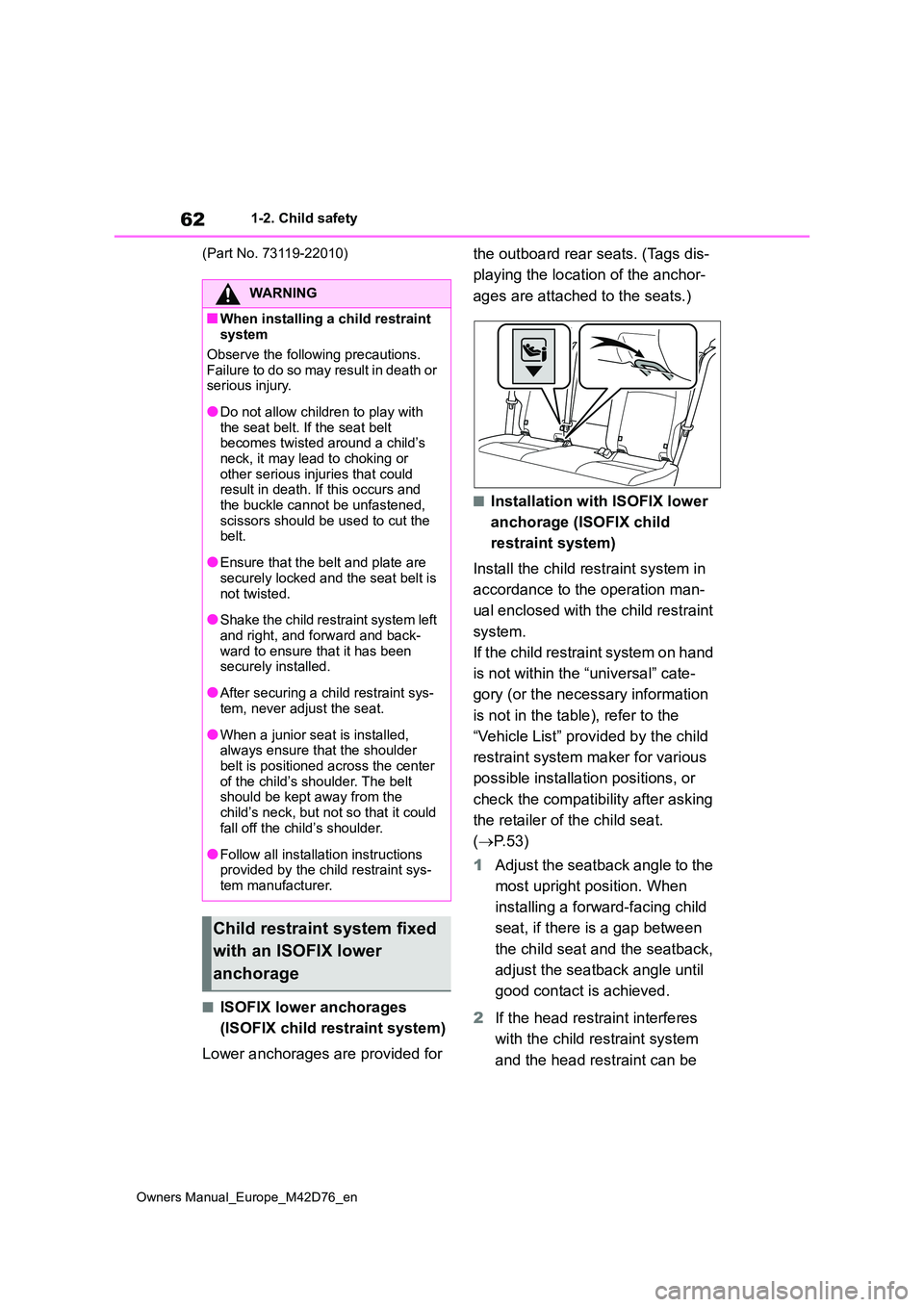
Lower anchorages are provided for
the outboard rear seats. (Tags dis-
playing the location of the anchor-
ages are attached to the seats.)
■Installation with ISOFIX lower
anchorage (ISOFIX child
restraint system)
Install the child restraint system in
accordance to the operation man-
ual enclosed with the child restraint
system.
If the child restraint system on hand
is not within the “universal” cate-
gory (or the necessary information
is not in the table), refer to the
“Vehicle List” provided by the child
restraint system maker for various
possible installation positions, or
check the compatibility after asking
the retailer of the child seat.
( P. 5 3 )
1 Adjust the seatback angle to the
most upright position. When
installing a forward-facing child
seat, if there is a gap between
the child seat and the seatback,
adjust the seatback angle until
good contact is achieved.
2 If the head restraint interferes
with the child restraint system
and the head restraint can be
WARNING
■When installing a child restraint system
Observe the following precautions.
Failure to do so may result in death or serious injury.
●Do not allow children to play with the seat belt. If the seat belt becomes twisted around a child’s
neck, it may lead to choking or other serious injuries that could result in death. If this occurs and
the buckle cannot be unfastened, scissors should be used to cut the belt.
●Ensure that the belt and plate are securely locked and the seat belt is
not twisted.
●Shake the child restraint system left
and right, and forward and back- ward to ensure that it has been securely installed.
●After securing a child restraint sys-tem, never adjust the seat.
●When a junior seat is installed, always ensure that the shoulder
belt is positioned across the center of the child’s shoulder. The belt should be kept away from the
child’s neck, but not so that it could fall off the child’s shoulder.
●Follow all installation instructions provided by the child restraint sys-tem manufacturer.
Child restraint system fixed
with an ISOFIX lower
anchorage
Page 65 of 674
63
1
Owners Manual_Europe_M42D76_en
1-2. Child safety
For safety and security
removed, remove the head
restraint. Otherwise, put the
head restraint in the upper most
position. ( P. 2 1 1 )
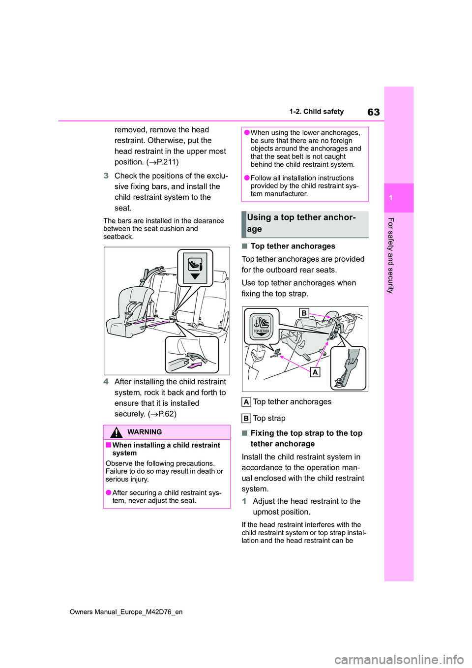
3 Check the positions of the exclu-
sive fixing bars, and install the
child restraint system to the
seat.
The bars are installed in the clearance between the seat cushion and seatback.
4 After installing the child restraint
system, rock it back and forth to
ensure that it is installed
securely. ( P. 6 2 )
■Top tether anchorages
Top tether anchorages are provided
for the outboard rear seats.
Use top tether anchorages when
fixing the top strap.
Top tether anchorages
Top strap
■Fixing the top strap to the top
tether anchorage
Install the child restraint system in
accordance to the operation man-
ual enclosed with the child restraint
system.
1 Adjust the head restraint to the
upmost position.
If the head restraint interferes with the child restraint system or top strap instal-lation and the head restraint can be
WARNING
■When installing a child restraint system
Observe the following precautions. Failure to do so may result in death or serious injury.
●After securing a child restraint sys-tem, never adjust the seat.
●When using the lower anchorages, be sure that there are no foreign objects around the anchorages and
that the seat belt is not caught behind the child restraint system.
●Follow all installation instructions provided by the child restraint sys-tem manufacturer.
Using a top tether anchor-
age
Page 67 of 674
65
1
Owners Manual_Europe_M42D76_en
1-3. Emergency assistance
For safety and security
1-3.Emerg ency as sista nce
*: Operates within the eCall coverage.
The system name differs depending
on the country.
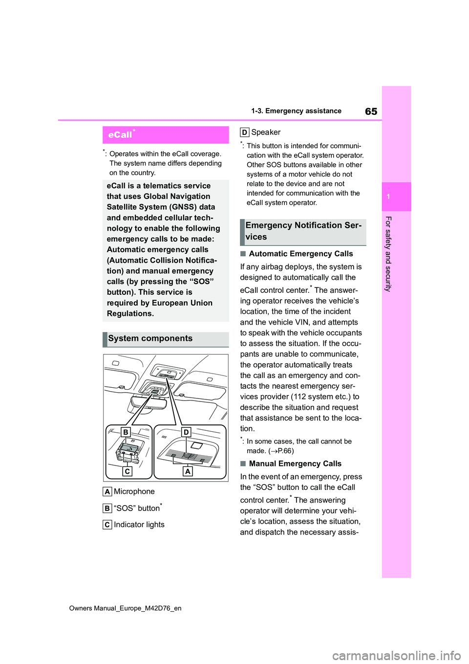
Microphone
“SOS” button*
Indicator lights
Speaker
*: This button is intended for communi-
cation with the eCall system operator.
Other SOS buttons available in other
systems of a motor vehicle do not
relate to the device and are not
intended for communication with the
eCall system operator.
■Automatic Emergency Calls
If any airbag deploys, the system is
designed to automatically call the
eCall control center.* The answer-
ing operator receives the vehicle’s
location, the time of the incident
and the vehicle VIN, and attempts
to speak with the vehicle occupants
to assess the situation. If the occu-
pants are unable to communicate,
the operator automatically treats
the call as an emergency and con-
tacts the nearest emergency ser-
vices provider (112 system etc.) to
describe the situation and request
that assistance be sent to the loca-
tion.
*: In some cases, the call cannot be
made. ( P. 6 6 )
■Manual Emergency Calls
In the event of an emergency, press
the “SOS” button to call the eCall
control center.* The answering
operator will determine your vehi-
cle’s location, assess the situation,
and dispatch the necessary assis-
eCall*
eCall is a telematics service
that uses Global Navigation
Satellite System (GNSS) data
and embedded cellular tech-
nology to enable the following
emergency calls to be made:
Automatic emergency calls
(Automatic Collision Notifica-
tion) and manual emergency
calls (by pressing the “SOS”
button). This service is
required by European Union
Regulations.
System components
Emergency Notification Ser-
vices
Page 68 of 674
66
Owners Manual_Europe_M42D76_en
1-3. Emergency assistance
tance required.
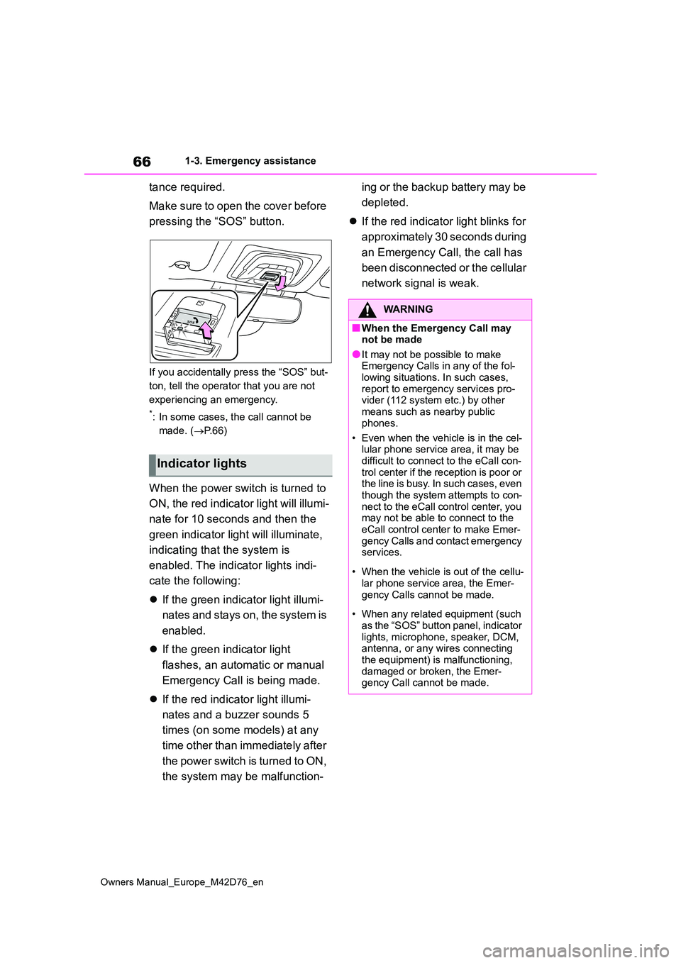
Make sure to open the cover before
pressing the “SOS” button.
If you accidentally press the “SOS” but-
ton, tell the operator that you are not
experiencing an emergency.
*: In some cases, the call cannot be
made. ( P. 6 6 )
When the power switch is turned to
ON, the red indicator light will illumi-
nate for 10 seconds and then the
green indicator light will illuminate,
indicating that the system is
enabled. The indicator lights indi-
cate the following:
If the green indicator light illumi-
nates and stays on, the system is
enabled.
If the green indicator light
flashes, an automatic or manual
Emergency Call is being made.
If the red indicator light illumi-
nates and a buzzer sounds 5
times (on some models) at any
time other than immediately after
the power switch is turned to ON,
the system may be malfunction-
ing or the backup battery may be
depleted.
If the red indicator light blinks for
approximately 30 seconds during
an Emergency Call, the call has
been disconnected or the cellular
network signal is weak.
Indicator lights
WARNING
■When the Emergency Call may not be made
●It may not be possible to make Emergency Calls in any of the fol-lowing situations. In such cases,
report to emergency services pro- vider (112 system etc.) by other means such as nearby public
phones.
• Even when the vehicle is in the cel- lular phone service area, it may be
difficult to connect to the eCall con- trol center if the reception is poor or the line is busy. In such cases, even
though the system attempts to con- nect to the eCall control center, you may not be able to connect to the
eCall control center to make Emer- gency Calls and contact emergency services.
• When the vehicle is out of the cellu- lar phone service area, the Emer-
gency Calls cannot be made.
• When any related equipment (such
as the “SOS” button panel, indicator lights, microphone, speaker, DCM, antenna, or any wires connecting
the equipment) is malfunctioning, damaged or broken, the Emer-gency Call cannot be made.