ESP TOYOTA BZ4X 2023 User Guide
[x] Cancel search | Manufacturer: TOYOTA, Model Year: 2023, Model line: BZ4X, Model: TOYOTA BZ4X 2023Pages: 628, PDF Size: 11.91 MB
Page 67 of 628
671-3. Emergency assistance
Owners Manual_USA_M42C01_en
1
For safety and security
the road, push the “SOS” button
to reach the Safety Connect
response center. The answer-
ing agent will determine your
vehicle’s location, assess the
emergency, and dispatch the
necessary assistance required.
If you accidentally press the “SOS”
button, tell the response-center
agent that you are not experiencing
an emergency.
■Enhanced Roadside Assis-
tance
Enhanced Roadside Assistance
adds GPS data to the already
included warranty-based Toyota
roadside service.
Subscribers can press the
“SOS” button to reach a Safety
Connect response-center agent,
who can help with a wide range
of needs, such as: towing, flat
tire, fuel delivery, etc. For a
description of the Enhanced
Roadside Assistance services
and their limitations, please see
the Safety Connect Terms and
Conditions, which are available
at Toyota.com.
Important! Read this informa-
tion about exposure to radio fre-
quency signals before using
Safety Connect;
The Safety Connect system
installed in your vehicle is a low- power radio transmitter and
receiver. It receives and also
sends out radio frequency (RF)
signals.
In August 1996, the Federal
Communications Commission
(FCC) adopted RF exposure
guidelines with safety levels for
mobile wireless phones. Those
guidelines are consistent with
the safety standards previously
set by the following U.S. and
international standards bodies.
ANSI (American National
Standards Institute) C95.1
[1992]
NCRP (National Council on
Radiation Protection and
Measurement) Report 86
[1986]
ICNIRP (International Com-
mission on Non-Ionizing Radi-
ation Protection) [1996]
Those standards were based on
comprehensive and periodic
evaluations of the relevant sci-
entific literature. Over 120 scien-
tists, engineers, and physicians
from universities, and govern-
ment health agencies and
industries reviewed the avail-
able body of research to
develop the ANSI Standard
(C95.1).
The design of Safety Connect
complies with the FCC guide-
lines in addition to those stan-
dards.
Safety information for
Safety Connect
Page 93 of 628
932-2. Charging
Owners Manual_USA_M42C01_en
2
Electric Vehicle system
■Locking the charging con-
nector
The AC charging connector will
be automatically locked when
inserting it into the AC charging
inlet.
(The setting can be
changed: P.93)
■Unlocking the charging
connector
The AC charging connector will
be unlocked when the doors are
unlocked using the smart key
system or wireless remote con-
trol.
The AC charging connector
locks when connected and
unlocks when the door is
unlocked, so locking/unlocking
the AC charging connector does
not necessarily correspond to
locking/unlocking the door. If the door is unlocked and the
AC charging connector is
locked, you can unlock it by
doing the following:
• When using the smart key
system, lock the door once
and then unlock it again.
( P.167)
• When using the wireless remote control, press the
unlock button to unlock the
door. ( P.167)
■Changing the AC charging
connector lock settings
The method for locking and
unlocking the AC charging con-
nector can be changed on the
multi-information display or mul-
timedia.
The charging connector lock
settings cannot be changed
when the AC charging cable is
connected to the vehicle.
The settings cannot be changed
when the power switch is in
ACC.
Multi-information display
operation
1 Press or of the meter
control switches to select
.
2 Press or of the meter
control switches to select
“Vehicle Settings”, and then
press and hold .
Locking and unlock-
ing AC charging con-
nector
The AC charging connector
will be locked when it is
connected to the AC
charging inlet, preventing
the AC charging cable from
being disconnected while
charging.
Locking and unlocking
the AC charging connec-
tor
Page 110 of 628
1102-2. Charging
Owners Manual_USA_M42C01_en
WARNING
●When charging outdoors, make
sure to connect to a weather-
proof outlet for outdoor use.
Ensure the weatherproof outlet
cover closes completely. If the
weatherproof outlet cover can-
not be closed, install a weather-
proof outlet cover that will close.
●In order to stop charging at the
charging station, follow the
instructions of the charger.
●If any heat, smoke, odors, noise
or other abnormalities are
noticed during charging, stop
charging immediately.
●Do not insert the plug if the out-
let is submerged in water or
snow.
●When charging while it is raining
or snowing, do not connect or
disconnect the plug if your
hands are wet. Also, do not get
the plug or outlet wet.
●Do not charge the vehicle
during a lightning storm.
●Prevent the AC charging cable
from being caught in the door or
back door.
●Do not let the wheels on the AC
charging cable, plug, charging
connector and CCID (Charging
Circuit Interrupting Device).
●Firmly insert the plug into the
outlet.
●Do not use an extension cord
and converting adaptor.
●Close the hood before using the
charging system.
The cooling fan may start oper-
ating suddenly. Touching or get-
ting close to rotating parts such
as the fan may cause your
hands or clothes (especially a
necktie or scarf) to become
caught and result in a serious
injury.
●After connecting the charging
cable, confirm that it is not
wound around anything.
●If the power indicator on the
CCID (Charging Circuit Inter-
rupting Device) does not illumi-
nate after plugging the AC
charging cable into the outlet,
unplug it immediately.
■If the error warn ing indicator
on the CCID (Charging Circuit
Interrupting Device) illumi-
nates or flashes during
charging
There may be an electrical leak-
age in the power source path, or
there may be a malfunction in the
AC charging cable or CCID
(Charging Circuit Interrupting
Device).
Refer to P.90 and follow the cor-
rection procedure. If the error
warning indicator does not turn off
even after performing the correc-
tion procedure, immediately stop
charging, remove the AC
charging cable and contact your
Toyota dealer. Continuing to
charge the vehicle in that condi-
tion may lead to u nforeseen acci-
dents or serious injury.
Page 116 of 628
1162-2. Charging
Owners Manual_USA_M42C01_en1
Be sure to engage the parking
brake and then turn the power
switch off.
2 Close the charging inlet cap,
close the charging port lid.
3 Check if “Checking Charging
System” is displayed on the
multi-information display when
the power switch is turned to ON.
Do not open the c harging port lid
while the charging system is check-
ing.
When the system check is com-
pleted, the power switch automati-
cally turns off.
4 Press the power switch while
depressing the brake pedal. The
“READY” indicator turns on.
Contact your Toyot a dealer if the
charging system check is done and
the message on the multi-informa-
tion display does not go off.
WARNING
■Warnings for DC charging
Be sure to observe the following
when using DC charging.
Failure to do so may cause an
accident that could lead to death
or serious injury.
●Check that the DC charger and
DC charging inlet are not dam-
aged. If there is any damage to
the DC charging inlet, do not
perform a DC charge and have
it inspected immediately at your
Toyota dealer.
●Do not touch the terminals of
the DC charging connector or
inlet with metallic sharp tips
(wires and needles), or allow a
short circuit to occur with foreign
objects.
●Do not insert anything other
than the DC charging connector
into the DC charging inlet.
●Check that the DC charging
cable is not coiled up or pinned
underneath heavy objects.
●Be sure the DC charging inlet
makes direct contact with the
DC charging connector.
Do not connect conversion
adapters, extension cords, etc.,
between the DC charging con-
nector and DC ch arging inlet.
●When DC charging is inter-
rupted, follow the handling pro-
cedures of the DC charger.
Immediately stop the DC
charging when the re is an out-
break of heat, smoke, strange
noises or smells, etc., during
charging.
●Check that the DC charging
connector and DC charging inlet
do not have foreign objects or
snow or ice attached to it. If any-
thing is attached t o the inlet, be
sure to complete ly remove the
material before connecting the
DC charging connector.
●Do not charge the vehicle when
there is a possibility of lightning.
If you notice lightning while
charging the vehicle, do not
touch the vehicle and the DC
charging cable.
●Do not get the DC charging inlet
terminals wet.
●Close the hood when using DC
charging. The cooling fan may
suddenly start to run. Keep
hands and clothing (especially a
tie, a scarf or a muffler) away
from the fan. Fa ilure to do so
may cause the hands or cloth-
ing to be caught, resulting in
serious injury.
Page 154 of 628
1543-1. Instrument cluster
Owners Manual_USA_M42C01_envehicle to your Toyota dealer.
●When the outside
temperature is
approximately 37°F (3°C) or
lower, the indicator will flash
for approximately 10 seconds,
then stay on.
■Liquid crystal display
P. 1 5 6
■Customization
The gauges and meters can be cus-
tomized in of th e multi-informa-
tion display. ( P.566)
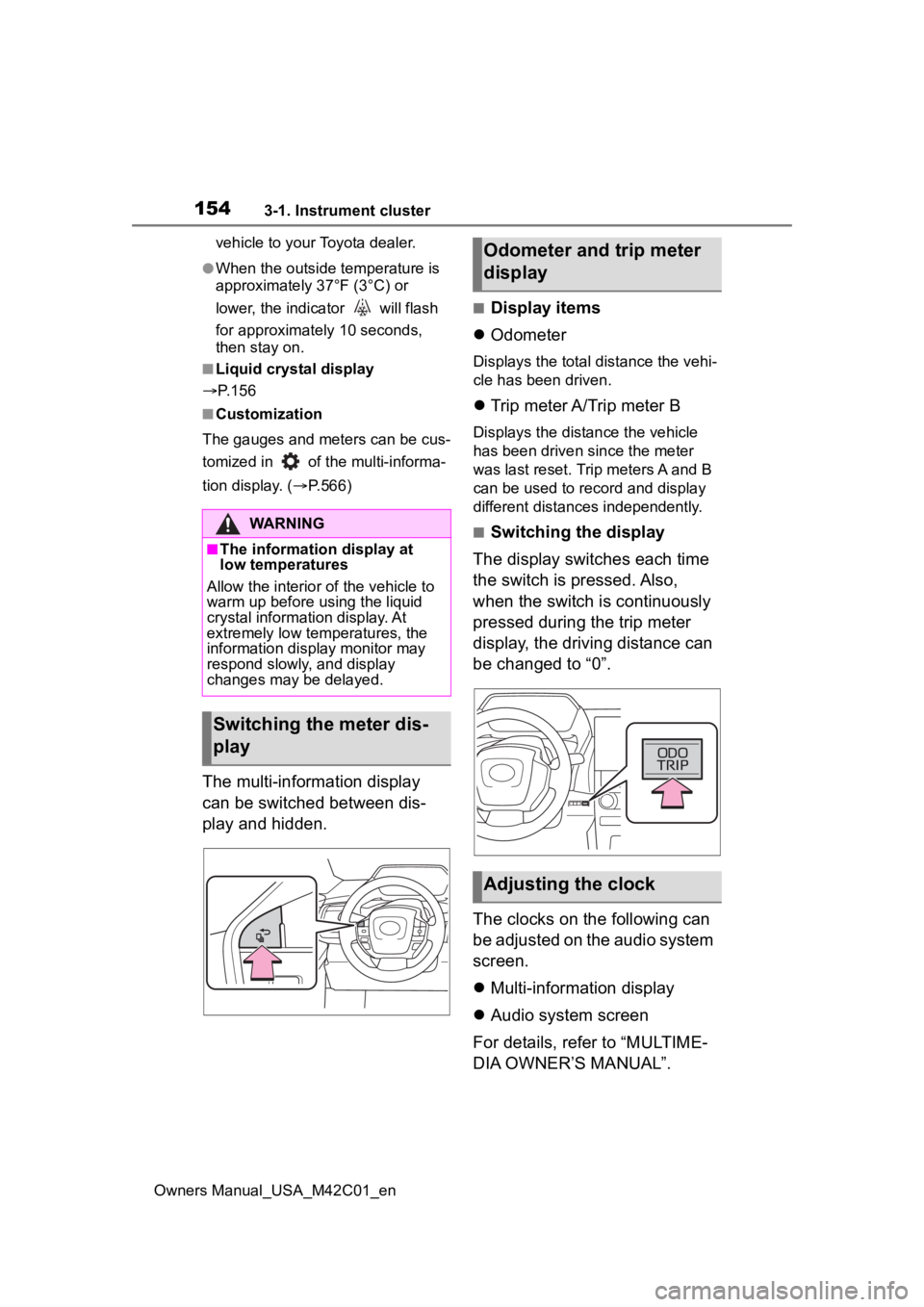
The multi-information display
can be switched between dis-
play and hidden.
■Display items
Odometer
Displays the total distance the vehi-
cle has been driven.
Trip meter A/Trip meter B
Displays the distance the vehicle
has been driven since the meter
was last reset. Trip meters A and B
can be used to record and display
different distances independently.
■Switching the display
The display switches each time
the switch is pressed. Also,
when the switch is continuously
pressed during the trip meter
display, the driving distance can
be changed to “0”.
The clocks on the following can
be adjusted on the audio system
screen.
Multi-information display
Audio system screen
For details, refer to “MULTIME-
DIA OWNER’S MANUAL”.WARNING
■The information display at
low temperatures
Allow the interior of the vehicle to
warm up before u sing the liquid
crystal informat ion display. At
extremely low temperatures, the
information display monitor may
respond slowly, and display
changes may be delayed.
Switching the meter dis-
play
Odometer and trip meter
display
Adjusting the clock
Page 157 of 628
1573-1. Instrument cluster
Owners Manual_USA_M42C01_en
3
Vehicle status information and indicators
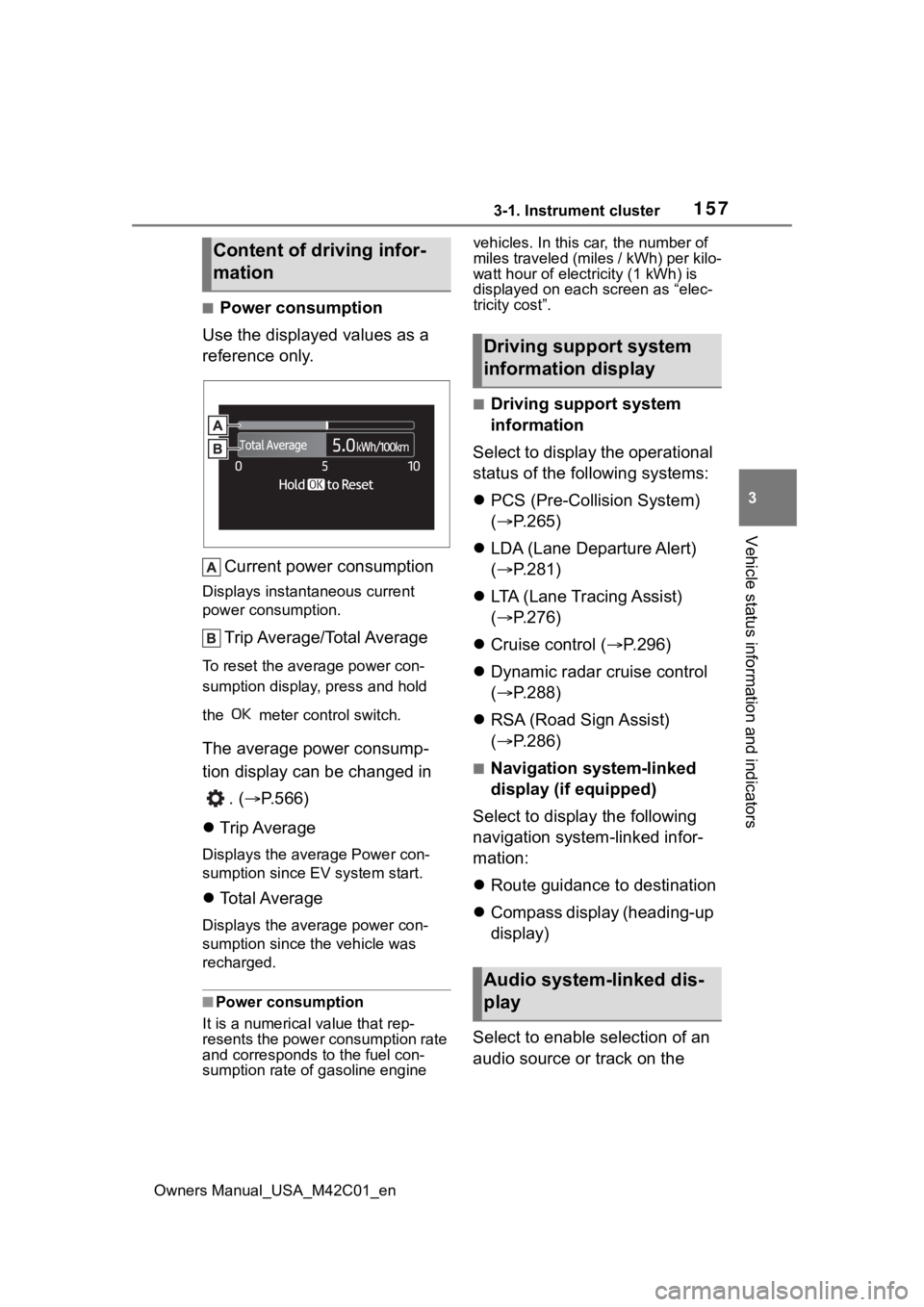
■Power consumption
Use the displayed values as a
reference only.
Current power consumption
Displays instant aneous current
power consumption.
Trip Average/Total Average
To reset the ave rage power con-
sumption display, press and hold
the meter control switch.
The average power consump-
tion display can be changed in
. ( P.566)
Trip Average
Displays the average Power con-
sumption since EV system start.
Total Average
Displays the aver age power con-
sumption since the vehicle was
recharged.
■Power consumption
It is a numerical value that rep-
resents the power consumption rate
and corresponds to the fuel con-
sumption rate of gasoline engine vehicles. In this car, the number of
miles traveled (miles / kWh) per kilo-
watt hour of elect
ricity (1 kWh) is
displayed on each screen as “elec-
tricity cost”.
■Driving support system
information
Select to display the operational
status of the following systems:
PCS (Pre-Colli sion System)
( P.265)
LDA (Lane Departure Alert)
( P.281)
LTA (Lane Tracing Assist)
( P.276)
Cruise control ( P.296)
Dynamic radar cruise control
( P.288)
RSA (Road Sign Assist)
( P.286)
■Navigation system-linked
display (if equipped)
Select to display the following
navigation system-linked infor-
mation:
Route guidance to destination
Compass display (heading-up
display)
Select to enable selection of an
audio source or track on the
Content of driving infor-
mation
Driving support system
information display
Audio system-linked dis-
play
Page 159 of 628
1593-1. Instrument cluster
Owners Manual_USA_M42C01_en
3
Vehicle status information and indicators
• Power consumption display
Select to change the average
power consumption display Trip
Average/Total Average. ( P.157)
Select to display/not display the
audio system linked display.
Select to change the displayed con-
tent of the following:
• Display contents (AWD models
only)
Select to display/not display the
torque distribution display.
• Drive information type
Select to change the drive informa-
tion type display between after
start/after reset.
• Drive information items
Select to set the first and second
items of the drive information dis-
play to any of the following: aver-
age vehicle
speed/distance/elapsed time.
Closing Display
Select to set the i tems displayed
when the power switch is turned off.
Pop-up display
Select to enable/disable pop-up
displays for each relevant system.
Calendar
The year, month, and day can be
set.
Default setting
Select to reset the meter display settings to the default setting.
■Vehicle functions and set-
tings that can be changed
P.566
■Suspension of the settings dis-
play
●Some settings cannot be changed
while driving. When changing set-
tings, park the vehicle in a safe
place.
●If a warning message is displayed,
operation of the settings display
will be suspended.
Displays suggestions to the
driver in the following situations.
To select a response to a dis-
played suggestion, use the
meter control switches.
■Suggestion to turn on the
headlights
If the headlight switch is in other
than or , and the vehicle
speed is 3 mph (5 km/h) or
higher for a certain amount of
time when the surroundings are
dark, a suggestion message will
be displayed.
NOTICE
■During setting up the display
To prevent 12-volt battery dis-
charge, ensure that the EV sys-
tem is operating while setting up
the display features.
Suggestion function
Page 166 of 628

1664-1. Key information
Owners Manual_USA_M42C01_en
key of the vehicle if traveling
to a location with unreliable
communications.
If the smartphone battery is
depleted, the smartphone
cannot be used as Digital Key.
If the battery level is low, be
sure to charge the smart-
phone prior to going out.
The Digital Key system is
related to the Smart key sys-
tem. If the Smart key system
has been deactivated in the
vehicle customization setting,
the Digital Key will also be
disabled.
Depending on the radio wave
environment, the Digital Key
may not be able to be used.
P. 1 8 8
When transferring vehicle
ownership, make sure to
delete the Digital Keys.
If the vehicle is not operated
for 14 days or more, the Digi-
tal Key will not connect auto-
matically. Therefore, it may
take some time before the
system operates after a door
handle is touched.
A part of the services may be
stopped for a certain period of
time due to server mainte-
nance. However, registered
Digital Keys can be used
during the maintenance.
A smartphone with the Digital
Key App enabled will be able to lock and unlock the doors,
start the EV system and per-
form any other operations as
same as the electronic key of
the vehicle. Be especially
careful not to lose the smart-
phone or allow it to be stolen.
If the smartphone is lost or
stolen, contact your Toyota
dealer immediately.
When taking your vehicle to a
Toyota dealer for an inspec-
tion or repairs, make sure to
bring an electronic key.
Page 170 of 628
1704-2. Opening, closing and locking the doors
Owners Manual_USA_M42C01_en
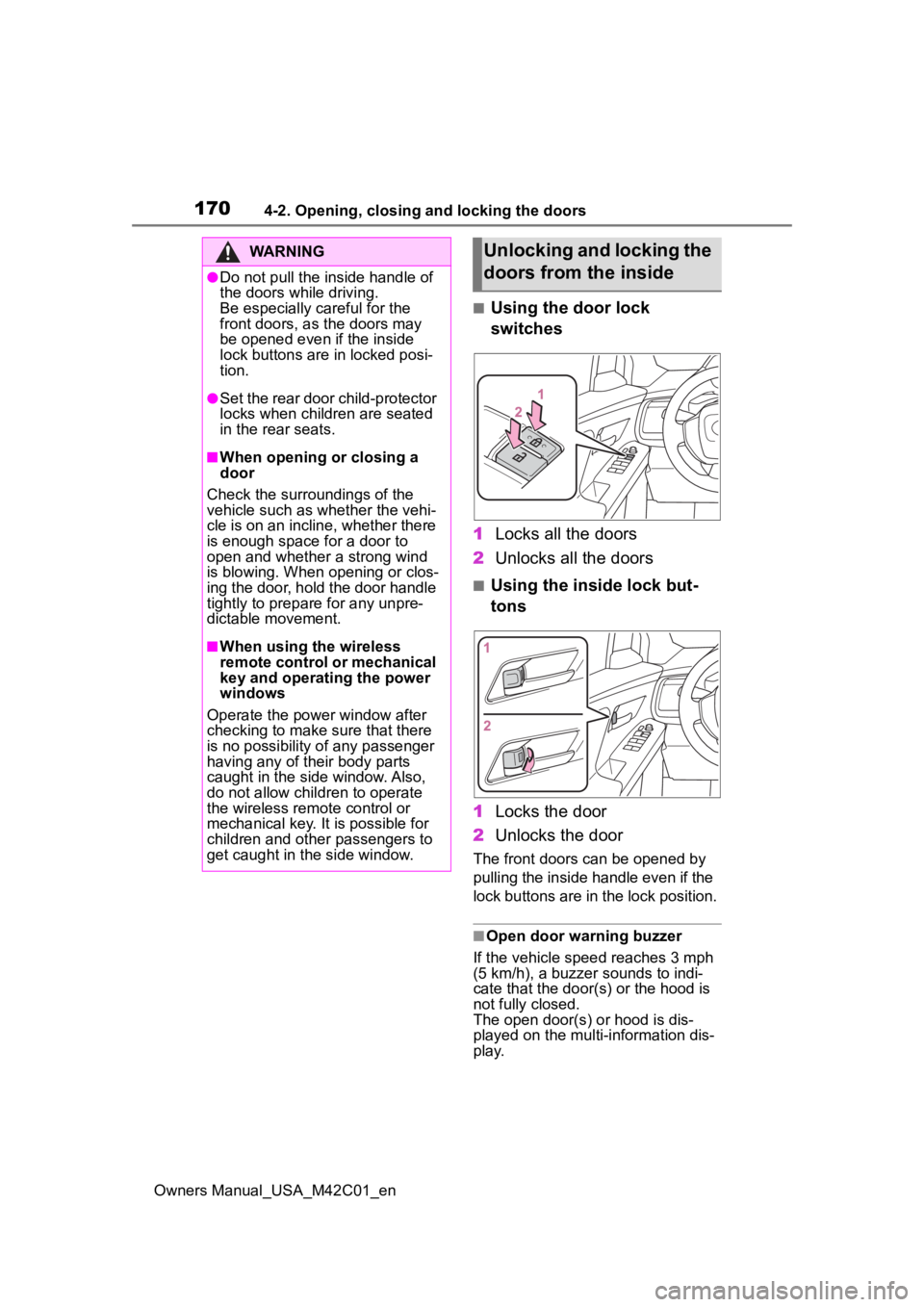
■Using the door lock
switches
1 Locks all the doors
2 Unlocks all the doors
■Using the inside lock but-
tons
1 Locks the door
2 Unlocks the door
The front doors can be opened by
pulling the inside handle even if the
lock buttons are in the lock position.
■Open door warning buzzer
If the vehicle speed reaches 3 mph
(5 km/h), a buzzer sounds to indi-
cate that the door( s) or the hood is
not fully closed.
The open door(s) or hood is dis-
played on the multi-information dis-
play.
WARNING
●Do not pull the inside handle of
the doors while driving.
Be especially careful for the
front doors, as the doors may
be opened even if the inside
lock buttons are in locked posi-
tion.
●Set the rear door child-protector
locks when children are seated
in the rear seats.
■When opening or closing a
door
Check the surroundings of the
vehicle such as whether the vehi-
cle is on an incline, whether there
is enough space for a door to
open and whether a strong wind
is blowing. When opening or clos-
ing the door, hold the door handle
tightly to prepare for any unpre-
dictable movement.
■When using the wireless
remote control or mechanical
key and operating the power
windows
Operate the power window after
checking to make sure that there
is no possibility of any passenger
having any of their body parts
caught in the side window. Also,
do not allow children to operate
the wireless remote control or
mechanical key. It is possible for
children and other passengers to
get caught in the side window.
Unlocking and locking the
doors from the inside
Page 195 of 628
1954-3. Adjusting the seats
Owners Manual_USA_M42C01_en
4
Before driving
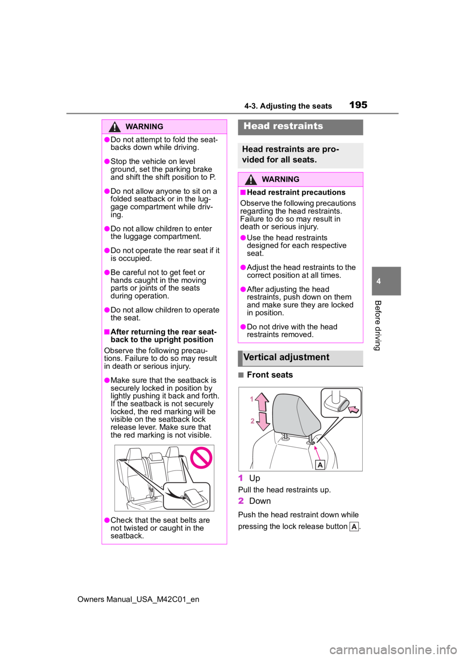
■Front seats
1 Up
Pull the head restraints up.
2Down
Push the head restraint down while
pressing the lock release button .
WARNING
●Do not attempt t o fold the seat-
backs down while driving.
●Stop the vehicle on level
ground, set the parking brake
and shift the shift position to P.
●Do not allow anyo ne to sit on a
folded seatback or in the lug-
gage compartment while driv-
ing.
●Do not allow child ren to enter
the luggage compartment.
●Do not operate the rear seat if it
is occupied.
●Be careful not to get feet or
hands caught in the moving
parts or joints of the seats
during operation.
●Do not allow children to operate
the seat.
■After returning the rear seat-
back to the upright position
Observe the following precau-
tions. Failure to do so may result
in death or serious injury.
●Make sure that the seatback is
securely locked in position by
lightly pushing it back and forth.
If the seatback is not securely
locked, the red marking will be
visible on the seatback lock
release lever. Make sure that
the red marking is not visible.
●Check that the seat belts are
not twisted or caught in the
seatback.
Head restraints
Head restraints are pro-
vided for all seats.
WARNING
■Head restraint precautions
Observe the following precautions
regarding the head restraints.
Failure to do so may result in
death or serious injury.
●Use the head restraints
designed for each respective
seat.
●Adjust the head restraints to the
correct position at all times.
●After adjusting the head
restraints, push down on them
and make sure they are locked
in position.
●Do not drive with the head
restraints removed.
Vertical adjustment