traction control TOYOTA BZ4X 2023 Owner's Manual
[x] Cancel search | Manufacturer: TOYOTA, Model Year: 2023, Model line: BZ4X, Model: TOYOTA BZ4X 2023Pages: 628, PDF Size: 11.91 MB
Page 467 of 628
4677-3. Do-it-yourself maintenance
Owners Manual_USA_M42C01_en
7
Maintenance and care
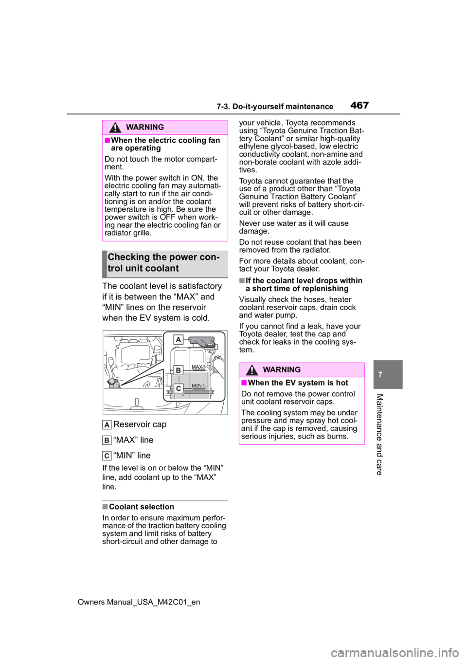
The coolant level is satisfactory
if it is between the “MAX” and
“MIN” lines on the reservoir
when the EV system is cold. Reservoir cap
“MAX” line
“MIN” line
If the level is on or below the “MIN”
line, add coolant up to the “MAX”
line.
■Coolant selection
In order to ensure maximum perfor-
mance of the traction battery cooling
system and limit risks of battery
short-circuit and other damage to your vehicle, Toyota recommends
using “Toyota Genuine Traction Bat-
tery Coolant” or similar high-quality
ethylene glycol-based, low electric
conductivity coolant, non-amine and
non-borate coolant with azole addi-
tives.
Toyota cannot guarantee that the
use of a product o
ther than “Toyota
Genuine Traction Battery Coolant”
will prevent risks of battery short-cir-
cuit or other damage.
Never use water as it will cause
damage.
Do not reuse cool ant that has been
removed from the radiator.
For more details about coolant, con-
tact your Toyota dealer.
■If the coolant level drops within
a short time of replenishing
Visually check the hoses, heater
coolant reservoir caps, drain cock
and water pump.
If you cannot find a leak, have your
Toyota dealer, t est the cap and
check for leaks in the cooling sys-
tem.
WARNING
■When the electric cooling fan
are operating
Do not touch the motor compart-
ment.
With the power switch in ON, the
electric cooling fan may automati-
cally start to run if the air condi-
tioning is on and/or the coolant
temperature is high. Be sure the
power switch is OFF when work-
ing near the electric cooling fan or
radiator grille.
Checking the power con-
trol unit coolant
WARNING
■When the EV system is hot
Do not remove the power control
unit coolant reservoir caps.
The cooling system may be under
pressure and may spray hot cool-
ant if the cap is removed, causing
serious injuries, such as burns.
Page 525 of 628
5258-2. Steps to take in an emergency
Owners Manual_USA_M42C01_en
8
When trouble arises
●AHB (Automatic High Beam)
●Dynamic radar cruise control
●RSA (Road Sign Assist)
Follow the followi ng correction
methods.
• The temperature of the radar sen- sor is outside of the operating
range. Wait for the temperature to
become appropriate.
■If “System Stopped Front Radar
In Self Calibration See Owner’s
Manual” is displayed
Indicates one of the following sys-
tems is disabled.
●PCS (Pre-Collis ion System)
●LDA (Lane Departure Alert)
●LTA (Lane Tracing Assist)
●AHB (Automatic High Beam)
●Dynamic radar cruise control
●RSA (Road Sign Assist)
Follow the followi ng correction
methods.
• Check if there is any foreign mat- ter attached to the radar sensor or
radar sensor cover and clean
them if necessary ( P.261)
• The radar sensor may be mis- aligned and will be adjusted auto-
matically while driving. Continue
driving for a while.
■If “Cruise Control Unavailable
See Owner’s Manual” is dis-
played
Indicates one of the following sys-
tems is disabled.
●Dynamic radar cruise control
●Cruise control
A message is displayed when the
driving assist s witch is pushed
repeatedly.
Press the driving assist switch
quickly and firmly.
■If a message that indicates the
need for visiting your Toyota
dealer is displayed
The system or part shown on the
multi-information di splay is malfunc-
tioning. Have the vehicle inspected
by your Toyota dealer immediately.
■If a message that indicates the
need for the rotary shifter oper-
ation is displayed
To prevent the rota ry shifter from
being operated incorrectly or the
vehicle from moving unexpectedly, a
message that requires shifting the
shift position may be displayed on
the multi-informatio n display. In that
case, follow the in struction of the
message and shift the shift position.
■If a message that indicates the
need for referring to Owner’s
Manual is displayed
●If any of the following messages
are shown on the multi-informa-
tion display, follow the instruc-
tions.
• “Battery Low” ( P.541)
• “Check Charging System Close Charging Port Lid” ( P.140)
• “Charging system malfunction”
( P.140)
• “Charging stopped High energy use” ( P.140)
●If any of the following messages
are shown on the multi-informa-
tion display, it may indicate a mal-
function. Have the vehicle
inspected by your Toyota dealer
immediately.
• “Entry & Start System Malfunction”
• “Traction battery system malfunc- tion”
• “Accelerator system malfunction”
• “Plug-in Charging System Mal- function”
• “EV system malfunction”
• “Shift System Mal function Apply
Parking Brake Securely When
Parking See Owner’s Manual”
• “Shift System M alfunction See
Owner’s Manual”
• “Shift System Malfunction Stop in
Page 537 of 628
5378-2. Steps to take in an emergency
Owners Manual_USA_M42C01_en
8
When trouble arises
One of the following may be the
cause of the problem:
The charging cable may be
connected to the vehicle.
( P.102)
The electronic key may not be
functioning properly.
*
( P.539)
The traction battery may be
completely discharged.
Charge the traction battery.
( P.98)
There may be a malfunction
in the immobilizer system.
*
( P.68)
There may be a malfunction
in the shift control system.
*
( P.233, 525)
The EV system may be mal-
functioning due to an electri-
cal problem such as
electronic key battery deple-
tion or a blown fuse. However,
NOTICE
●Do not put the repair kit directly
onto dusty ground such as sand
at the side of the road. If the
repair kit vacuums up dust, etc.,
a malfunction may occur.
●Make sure the sealant bottle of
the repair kit is in a vertical posi-
tion. The repair kit does not
operate properly when it is laid.
■Precautions for the emer-
gency tire puncture repair kit
●The repair kit power source
should be 12 V DC suitable for
vehicle use. Do not connect the
repair kit to any other source.
●Place the repair kit in a storage
to prevent it from being exposed
to dirt or water.
●Store the repair kit in the lug-
gage compartment out of reach
of children.
●Do not disassemble or modify
the repair kit. Do not subject
parts such as the air pressure
indicator to impacts. This may
cause a malfunction.
■To avoid damage to the tire
pressure warning valves and
transmitters
When a tire is repaired with liquid
sealants, the tire pressure warn-
ing valve and transmitter may not
operate properly. If a liquid seal-
ant is used, contact your Toyota
dealer or other qualified service
shop as soon as possible. After
use of liquid sealant, make sure to
replace the tire pressure warning
valve and transmitter when repair-
ing or replacing the tire. ( P.476)
If the EV system will
not star t
Reasons for the EV system
not starting vary depending
on the situation. Check the
following and perform the
appropriate procedure:
The EV system will not
start even though the cor-
rect starting procedure is
being followed ( P.231)
Page 538 of 628
5388-2. Steps to take in an emergency
Owners Manual_USA_M42C01_en
depending on the type of mal-
function, an interim measure
is available to start the EV
system. (P.538)
There is a possibility that the
temperature of the traction
battery is extremely low
(approximately below -22°F [-
30°C]). ( P.77, 232)
*: It may not be possible to shift the
shift position from P
One of the following may be the
cause of the problem:
The 12-volt battery may be
discharged. ( P.541)
The 12-volt battery terminal
connections may be loose or
corroded. ( P.468)
One of the following may be the
cause of the problem:
The 12-volt battery may be
discharged. ( P.541)
One or both of the 12-volt bat-
tery terminals may be discon-
nected. ( P.468)
Contact your Toyota dealer if the problem cannot be repaired, or if
repair procedures are unknown.
When the EV system does not
start, the following steps can be
used as an interim measure to
start the EV system if the power
switch is functioning normally.
Do not use this starting proce-
dure except in cases of emer-
gency.
1
Set the parking brake.
2 Turn the power switch to
ACC.
*
3Press and hold the power
switch for about 15 seconds
while depressing the brake
pedal firmly.
After pressing the power switch for
a while, a message regarding 12-
volt battery control will be dis-
played, however continuing press-
ing the switch.
Even if the EV system can be
started using the above steps,
the system may be malfunction-
ing. Have the vehicle inspected
by your Toyota dealer.
*: Setting can be customized.
( P.571)
The interior lights and
headlights are dim, or the
horn does not sound or
sounds at a low volume
The interior lights and
headlights do not turn on,
or the horn does not
sound
Starting the EV system in
an emergency
Page 559 of 628
5599-1. Specifications
Owners Manual_USA_M42C01_en
9
Vehicle specifications
tion on uniform tire quality grad-
ing.
Your Toyota dealer will help answer
any questions you may have as you
read this information.
■DOT quality grades
All passenger vehicle tires must
conform to Federal Safety
Requirements in addition to
these grades. Quality grades
can be found where applicable
on the tire sidewall between
tread shoulder and maximum
section width.
For example: Treadwear 200 Trac-
tion AA Temperature A
■Treadwear
The treadwear grade is a com-
parative rating based on the
wear rate of the tire when tested
under controlled conditions on a
specified government test
course.
For example, a tire graded 150
would wear one and a half (1 - 1/2)
times as well on the government
course as a tire graded 100.
The relative perfo rmance of tires
depends upon the actual conditions
of their use. Performance may differ
significantly from the norm due to
variations in driving habits, service
practices and differences in road
characteristics and climate.
■Traction AA, A, B, C
The traction grades, from high-
est to lowest, are AA, A, B and
C, and they represent the tire’s
ability to stop on wet pavement as measured under controlled
conditions on specified govern-
ment test surfaces of asphalt
and concrete.
A tire marked C may have poor
traction performance.
Warning: The traction grade
assigned to this tire is based on
braking (straight ahead) traction
tests and does not include corner-
ing (turning) traction.
■Temperature A, B, C
The temperature grades are A
(the highest), B, and C, repre-
senting the tire’s resistance to
the generation of heat and its
ability to dissipate heat when
tested under controlled condi-
tions on a specified indoor labo-
ratory test wheel.
Sustained high temperature can
cause the material of the tire to
degenerate and reduce tire life, and
excessive temperature can lead to
sudden tire failure.
Grade C corresponds to a level of
performance which all passenger
car tires must meet under the Fed-
eral Motor Vehicle Safety Standard
No. 109.
Grades B and A represent higher
levels of performance on the labo-
ratory test wheel than the minimum
required by law.
Warning: The temperature grades
of a tire assume tha t it is properly
inflated and not overloaded.
Excessive speed, underinflation, or
excessive loading, either sepa-
rately or in combination, can cause
Page 598 of 628
598Alphabetical Index
Owners Manual_USA_M42C01_en
Front seat concentrated airflow mode (S-FLOW) ................. 408
Remote Air Conditioning System ........................................... 409
“SYNC” mode ....................... 406
Automatic door locking and unlocking systems ............... 171
Automatic High Beam (AHB) . 250
Automatic light control system ............................................... 248
Auxiliary box lights ................ 415
Auxiliary boxes ....................... 420
Average power consumption 157
Average vehicle speed........... 158
B
Back door ................................ 172 Hands Free Power Back Door........................................... 177
Power back door .................. 175
Wireless remote control 164, 175
Back-up lights Replacing light bulbs ............ 502
Battery (12-volt battery) If the 12-volt battery is dis-charged .............................. 541
Preparing and c hecking before
winter.................................. 393
Replacing ............................. 544
Warning light ........................ 513
Battery (traction battery) ......... 72 Charging....................... 105, 113
Location.................................. 72
Specification ......................... 552
Traction battery cooler............ 99
Traction battery heater ........... 99
Warning messages............... 140
Battery Electric Vehicle driving tips ........................................... 81
Blind Spot Monitor (BSM) ...... 302 Enabling/disabling the system........................................... 303 Bottle holders .........................420
Brake
Brake Hold ............................246
Fluid......................................554
Parking brake .......................243
Regenerative braking .............73
Warning light.........................513
Brake assist ............................387 Brake Hold ............................246
Brake Override System ..........220
Break-in tips ............................220
Brightness control Instrument panel light control155
BSM (Blind Spot Monitor) ......302 Enabling/disabling the system...........................................303C
Camera Digital Rear-view Mirror ........206
Front camera ........................260
Toyota Teammate Advanced Park ....................................352
Card holders ...........................420
Care Aluminum wheels .................449
Brake calipers.......................449
Exterior .................................448
Interior ..................................451
Seat belts .............................451
Cargo and luggage .................225
Cargo capacity ................225, 228
Cargo hooks............................421
CCID (Charging Circuit Interrupt- ing Device) ..............................89Indicator..................................90
Operation................................90
Ceintures de sécurité Comment porter votre ceinture de sécurité ..........................581
Center console light ...............415
Chains......................................395
Page 599 of 628

Owners Manual_USA_M42C01_en
Alphabetical Index599
Charging ......................... 105, 113AC charging ......................... 105
AC charging cable .................. 87
Charging components ............ 85
Charging indicator .................. 90
Charging methods .................. 98
Charging procedure ..... 105, 113
Charging schedule function.. 118
Charging time may increase 104
Charging tips ........................ 100
DC charging ......................... 113
Display . 101, 121, 129, 131, 140
Information related to charging display 101, 121 , 129, 131, 140
Locking and unlocking the AC charging connector............... 93
My Room Mode .................... 129
Opening and closing the charging port lid s .................. 85
Power sources precautions .... 97
Power sources th at can be used
............................................. 96
Safety functions.............. 89, 102
Things to know before charging ........................................... 102
Warning messages............... 140
When AC charging cannot be performed ........................... 133
When charging schedule func- tion cannot be performed ... 138
When DC charging cannot be performed ........................... 135
Charging equipment ................ 85
Charging methods.................... 98 AC charging ......................... 105
DC charging ......................... 113
Charging ports Charging port lid ..................... 85
Locking and unlocking the AC charging connector............... 93
Opening and closing .............. 85
Charging schedule function .. 118 Setting ..................................121
Charging tips ..........................100
Charging-linked functions My Room Mode ......................98
Traction battery cooler ............99
Traction battery heater ...........99
Traction battery warming control.............................................99
Child restraint system ..............50 Fixed with a LATCH system ...59
Fixed with a seat belt..............54
Front passenger occupant clas-sification system ...................44
Points to remember ................50
Riding with children ................49
Types of child restraint system installation method ...............52
Using an anchor bracket ........61
Child safety ...............................49 12-volt battery precautions ...544
Airbag precautions .................39
Back door precautions..........172
Child restraint system .............52
Electronic sunshade .............427
How your child should wear the seat belt ................................30
Power window lock switch ....214
Power window precautions...213
Rear door child-protectors ....171
Seat belt extender precautions .............................................30
Seat belt precautions........29, 49
Child-protector........................171
Cleaning ..........................448, 451 Aluminum wheels .................449
Brake calipers.......................449
Digital Rear-view Mirror ........206
Exterior .................................448
Interior ..................................451
Radar sensor ........................261
Seat belts .............................451
Clock ................................152, 154
Page 601 of 628
Owners Manual_USA_M42C01_en
Alphabetical Index601
Battery Electric Vehicle driving tips........................................ 81
Break-in tips ......................... 220
Correct posture ...................... 27
Procedures ........................... 219
Winter drive tips ................... 393
Driving assist information Warning light ........................ 517
Driving information display ... 157
Driving range .......................... 152
Driving support system informa- tion display ........................... 157
Dynamic radar cruise control ....................................... 288, 296Approach warning ................ 294
Curve speed redu ction function
........................................... 295
Warning lights....................... 518
E
ECB (Electronically Controlled Brake System) ...................... 387Warning light ........................ 513
Eco mode ................................ 241
EDR (Event data recorder)......... 9
Elapsed time ........................... 158
Electric motor (traction motor) Location.................................. 72
Electric motor(traction motor) Identification number ............ 551
Electric Power Steering (EPS) Function ............................... 387
Warning light ........................ 515
Electric Vehicle system features ................................................. 72
Electric Vehicle system precau-
tions......................................... 76
Electronic key Battery-saving function......... 188
If the electronic key does not operate properly ................. 539
Replacing the battery ........... 497 Electronic sunshade ..............426
Operation..............................426
Electronically Controlled Brake System (ECB) ........................387Warning light.........................513
Emergency Driving Stop System ...............................................299
Emergency flashers ...............504
Emergency tire puncture repair kit ...........................................527Storage location ...................528
Emergency, in case of If a warning buzzer sounds ..513
If a warning light turns on .....513
If a warning message is dis-played .................................522
If the 12-volt battery is dis- charged ..............................541
If the electronic key does not operate properly .................539
If the EV system will not start537
If the vehicle is submerged or water on the road is rising ..506
If you have a flat tire .............527
If you lose your keys.............539
If you think something is wrong ........................................... 511
If your vehicle becomes stuck ...........................................547
If your vehicle has to be stopped in an emergency .................505
If your vehicle needs to be towed ...........................................507
If your vehicle ove rheats ......545
Engine Hood .....................................462
EPS (Electric Po wer Steering)
Function................................387
Warning light.........................515
EV system .................................72 ACC ......................................234
Acoustic Vehicle Alerting System
Page 602 of 628
602Alphabetical Index
Owners Manual_USA_M42C01_en
............................................. 74
Battery Electric Vehicle driving tips........................................ 81
Brake Override System ........ 220
Drive-start control ................. 224
Driving range .......................... 83
Electric Vehicle system precau- tions...................................... 76
Emergency shut off system .... 80
Features ................................. 72
How to start the EV system .. 231
How to use AC charging....... 105
How to use DC charging ...... 113
If the EV system will not start537
If your vehicle has to be stopped in an emergency................. 505
Ignition switch (power switch) ........................................... 231
Overheating.......................... 545
Power meter ......................... 152
Power switch ........................ 231
Regenerative braking ............. 73
Starting the EV system......... 231
Event data recorder (EDR)......... 9
F
Flat tire .................................... 527 Tire pressure warning system........................................... 474
Floor mats ................................. 26
Fluid Brake .................................... 554
Front eAxle ........................... 554
Rear eAxle ........................... 554
Washer ................................. 471
Fog light Replacing light bulbs ............ 502
Footwell lights ..... ................... 415
Front eAxle Fluid ..................................... 554
Front electric mo tor (traction
motor) Specification .........................551
Front fog light Replacing light bulbs ............502
Front interior lig hts ................416
Front passenger occupant clas- sification system ....................44
Front seat concentrated airflow mode (S-FLOW) ....................408
Front seats ..............................192 Adjustment ...........................192
Cleaning ...............................451
Correct driving posture ...........27
Head restraints .....................196
Seat heaters ......................... 411
Seat ventilators..................... 411
Front side marker lights.........248 Light switch...........................248
Front turn signal lights Replacing light bulbs ............502
Turn signal lever ...................242
Fuses .......................................499
G
Garage door opene r ...............439
Gauges ....................................152
Grip Control ............................385
H
Head restraints .......................196
Headlights ...............................248 Automatic High Beam (AHB) 250
Light switch...........................248
Replacing light bulbs ............502
Headlights aim ........................501 Headlight aim instructions for Canadian owners ...............590
Heated steering wheel............ 411
Heater system Capacity ...............................553
Page 603 of 628
Owners Manual_USA_M42C01_en
Alphabetical Index603
HeatersAutomatic air conditioning sys-tem ..................................... 402
Heated steering wheel ......... 412
Outside rear view mirrors ..... 404
Seat heaters ......................... 411
Traction battery heater ........... 99
Hill-start assist control .......... 387
Hood ........................................ 462
Hooks Cargo hooks ......................... 421
Coat hooks ........................... 437
Retaining hooks (floor mat) .... 26
Horn ......................................... 199
I
I/M test ..................................... 459
Identification Electric motor (traction motor)........................................... 551
Vehicle.................................. 550
If your vehicle ove rheats ....... 545
Ignition switch (power switch) ............................................... 231Auto power off function ........ 235
Changing the power switch modes ................................ 234
If your vehicle has to be stopped in an emergency................. 505
Starting the EV system......... 231
Illuminated entry system ....... 415
Immobilizer system .................. 68
Indicators ................................ 149 Charging cable ....................... 90
Charging indicator .................. 86
Charging indicator (CCID) ...... 90
Error warning indicator ........... 90
Power indicator ...................... 90
Initialization Electronic sunshade ............. 426
Items to initialize................... 577
Parking Support Brake ......... 335 Power back door ..................181
Power windows ....................212
Inside door handle lights .......415
Inside rear view m irror ...........200
Interior lights...........................415
Intuitive parking assist........... 311 Enabling/disabling the system...........................................312
Function................................ 311
Warning lights .......................517
J
Jack Positioning a floor jack .........464
Vehicle-equipped jack ..........486
Jack handle .............................486
Jam protection function Power back door ..................179
Power windows ....................212
K
Keyless entrySmart key system .................187
Wireless remote control........164
Keys .........................................162 Battery-saving function .........188
Digital key .............................165
Electronic key .......................162
If the electronic key does not operate properly .................539
If you lose your keys.............539
Key number plate .................162
Keyless entry ................164, 187
Mechanical key.....................164
Power switch ........................231
Replacing the battery ...........497
Warning buzzer ....................187
Wireless remote control key .164
Knee airbags .............................34