door unlock TOYOTA BZ4X 2023 Owners Manual
[x] Cancel search | Manufacturer: TOYOTA, Model Year: 2023, Model line: BZ4X, Model: TOYOTA BZ4X 2023Pages: 628, PDF Size: 11.91 MB
Page 14 of 628
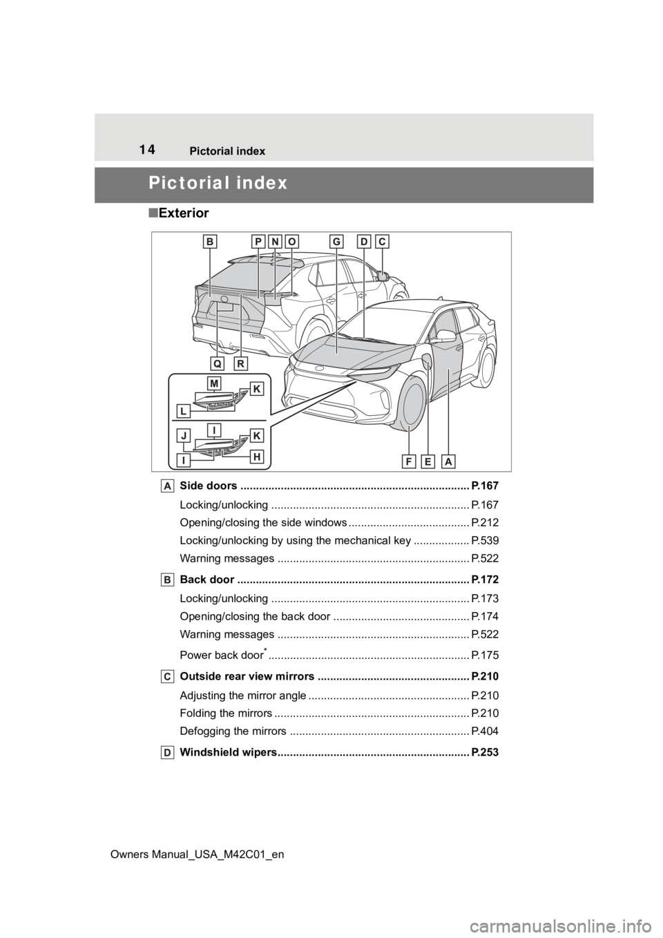
14Pictorial index
Owners Manual_USA_M42C01_en
Pictorial index
■ Exterior
Side doors ......... ................................. ................................ P.167
Locking/unlocking .............................................. .................. P.167
Opening/closing the side windows ............................... ........ P.212
Locking/unlocking by using the mechanical key .................. P. 5 3 9
Warning messages ............................................... ............... P.522
Back door ...................................................... ..................... P.172
Locking/unlocking .............................................. .................. P.173
Opening/closing the back d oor ............................................ P.174
Warning messages ............................................... ............... P.522
Power back door
*............................................................... .. P.175
Outside rear view mirrors ................................................. P.210
Adjusting the mirror angle ..................................... ............... P.210
Folding the mirrors ............................................ ................... P.210
Defogging the mirrors .......................................... ................ P.404
Windshield wipers.............................................. ................ P.253
Page 36 of 628

361-1. For safe use
Owners Manual_USA_M42C01_en
Front passenger occupant classification sensors
SRS warning light
Airbag sensor assembly
Your vehicle is equipped with ADVANCED AIRBAGS designed
based on the US motor vehicle safety standards (FMVSS208). The
airbag sensor assembly (ECU) cont rols airbag deployment based on
information obtained from the sensors etc. shown in the system
components diagram above. This in formation includes crash sever-
ity and occupant information. As the airbags deploy, a chemical
reaction in the inflators quickly fills the airbags with non-toxic gas to
help restrain the motion of the occupants.
■If the SRS airbags deploy
(inflate)
●Slight abrasions, burns, bruising
etc., may be sustained from SRS
airbags, due to the extremely high
speed deployment (inflation) by
hot gases.
●A loud noise and white powder will
be emitted.
●Parts of the airbag module (steer-
ing wheel hub, airbag cover and
inflator) as well as the front seats,
parts of the front and rear pillars,
and roof side rails, may be hot for
several minutes. T he airbag itself
may also be hot.
●The windshield may crack.
●The EV system will be stopped.
( P. 8 0 )
●All of the doors will be unlocked.
( P.168)
●The brakes and st op lights will be
controlled automatically. ( P.388)
●The interior lights will turn on auto-
matically. ( P.416)
●The emergency flashers will turn
on automatically. ( P.504)
●For Safety Connect subscribers, if
any of the following situations
occur, the system is designed to
send an emergency call to the
response center, notifying them of the vehicle’s location (without
needing to push the “SOS” button)
and an agent will attempt to speak
with the occupants to ascertain
the level of emergency and assis-
tance required. If the occupants
are unable to communicate, the
agent automatically treats the call
as an emergency and helps to dis-
patch the necessary emergency
services. (
P. 6 4 )
• An SRS airbag is deployed.
• A seat belt pretensioner is acti- vated.
• The vehicle is involved in a severe rear-end collision.
■SRS airbag deployment condi-
tions (SRS front airbags)
●The SRS front airbags will deploy
in the event of an impact that
exceeds the set threshold level
(the level of forc e corresponding
to an approximately 12 - 18 mph
[20 - 30 km/h] frontal collision with
a fixed wall that does not move or
deform).
However, this threshold velocity will
be considerably higher in the follow-
ing situations:
• If the vehicle strikes an object, such as a parked vehicle or sign
pole, which can move or deform
on impact
• If the vehicle is involved in an underride collision, such as a colli-
Page 69 of 628
691-4. Theft deterrent system
Owners Manual_USA_M42C01_en
1
For safety and security
■Items to check before lock-
ing the vehicle
To prevent unexpected trigger-
ing of the alarm and vehicle
theft, make sure of the following:
Nobody is in the vehicle.
The side windows are closed
before the alarm is set.
No valuables or other per-
sonal items are left in the
vehicle.
■Setting
Close the doors and hood, and
lock all the doors. The system
will be set automatically after 30
seconds.
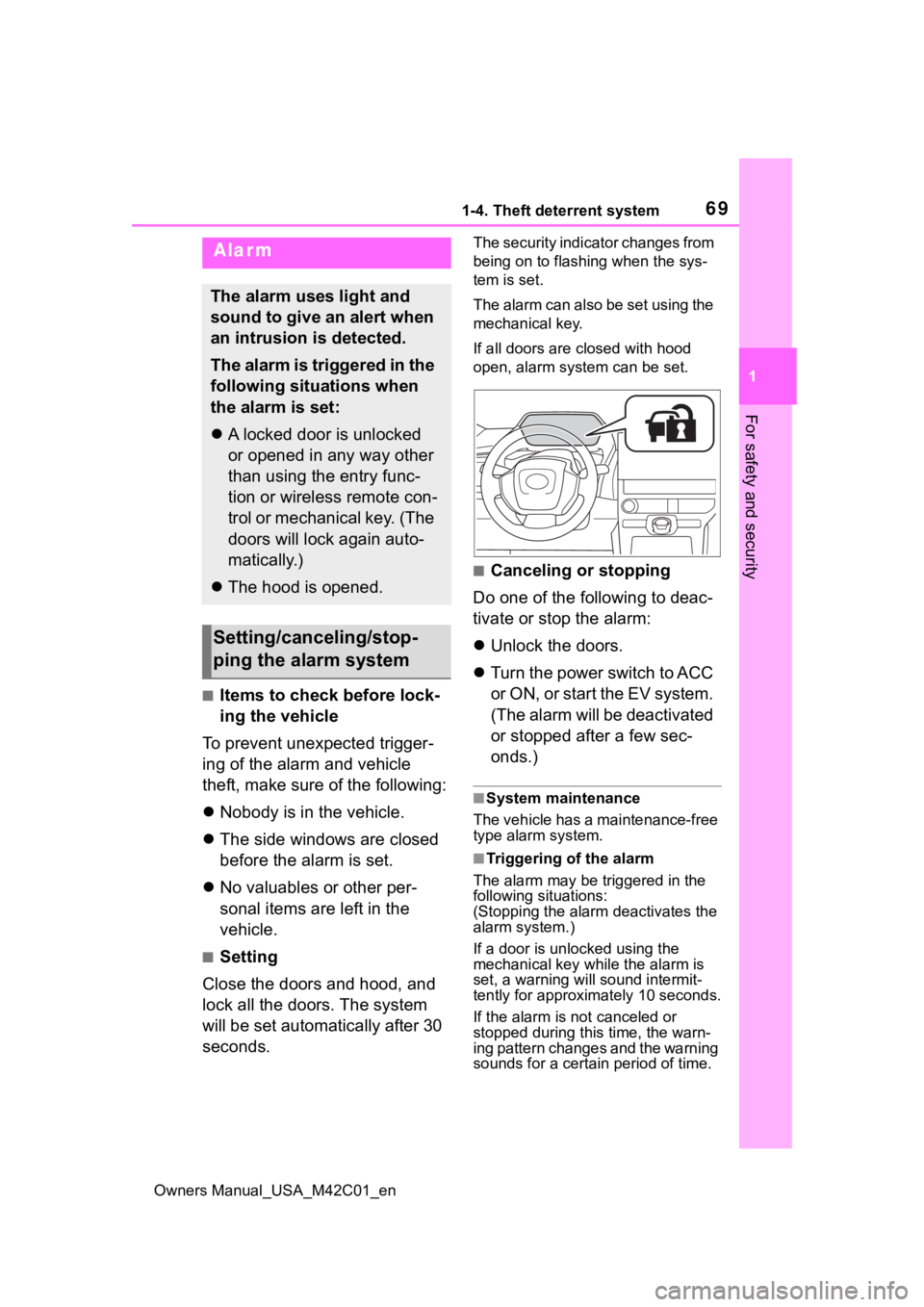
The security indicator changes from
being on to flashing when the sys-
tem is set.
The alarm can also be set using the
mechanical key.
If all doors are closed with hood
open, alarm system can be set.
■Canceling or stopping
Do one of the following to deac-
tivate or stop the alarm:
Unlock the doors.
Turn the power switch to ACC
or O N, or s tart the E V s ys tem .
(The alarm will be deactivated
or stopped after a few sec-
onds.)
■System maintenance
The vehicle has a maintenance-free
type alarm system.
■Triggering of the alarm
The alarm may be triggered in the
following situations:
(Stopping the alarm deactivates the
alarm system.)
If a door is unl ocked using the
mechanical key while the alarm is
set, a warning will sound intermit-
tently for approxi mately 10 seconds.
If the alarm is not canceled or
stopped during this time, the warn-
ing pattern changes and the warning
sounds for a certain period of time.
Alarm
The alarm uses light and
sound to give an alert when
an intrusion is detected.
The alarm is triggered in the
following situations when
the alarm is set:
A locked door is unlocked
or opened in any way other
than using the entry func-
tion or wireless remote con-
trol or mechanical key. (The
doors will lock again auto-
matically.)
The hood is opened.
Setting/canceling/stop-
ping the alarm system
Page 70 of 628
701-4. Theft deterrent system
Owners Manual_USA_M42C01_en
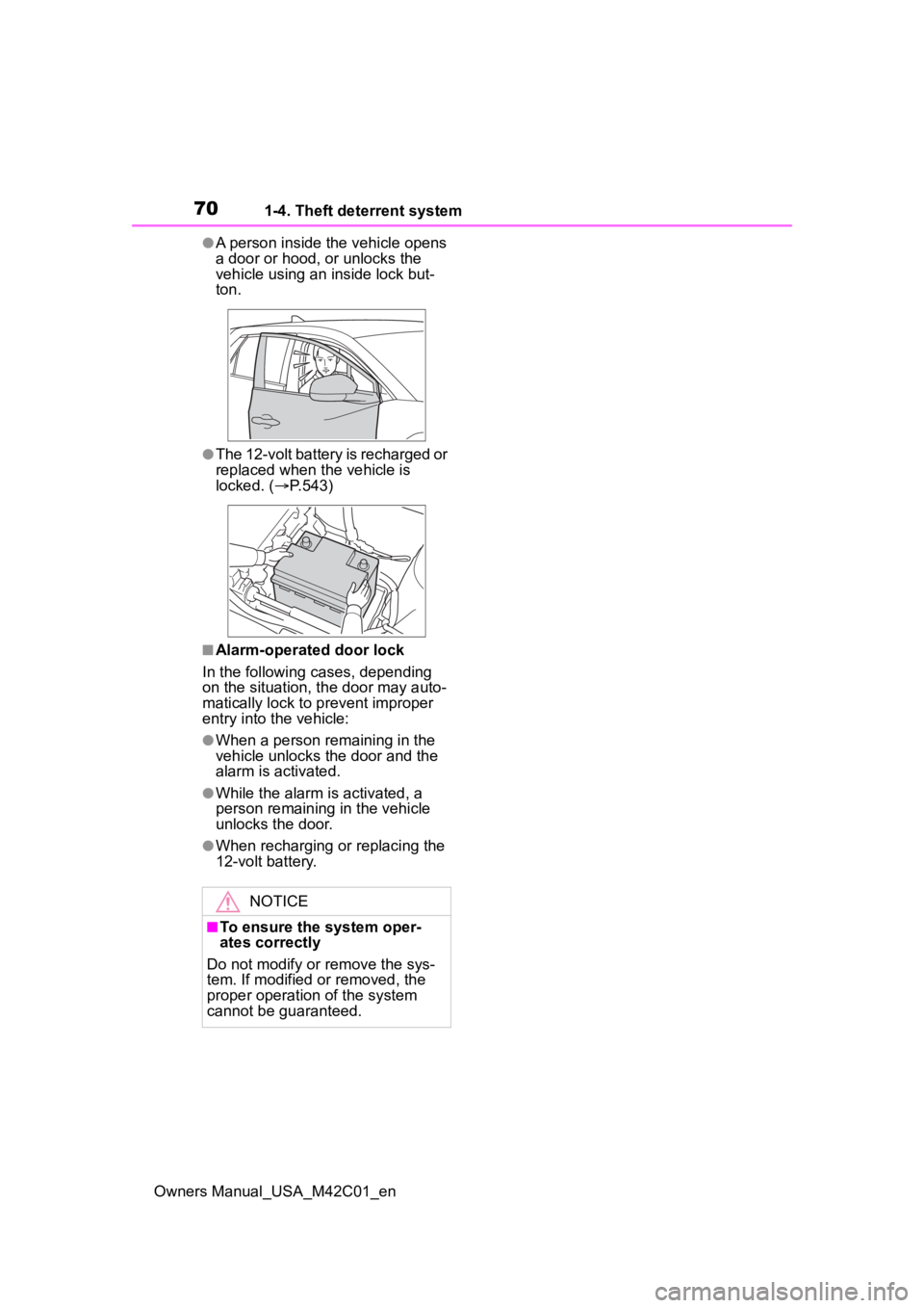
●A person inside the vehicle opens
a door or hood, or unlocks the
vehicle using an inside lock but-
ton.
●The 12-volt battery is recharged or
replaced when the vehicle is
locked. (P.543)
■Alarm-operated door lock
In the following cases, depending
on the situation, th e door may auto-
matically lock to p revent improper
entry into the vehicle:
●When a person remaining in the
vehicle unlocks the door and the
alarm is activated.
●While the alarm is activated, a
person remaining in the vehicle
unlocks the door.
●When recharging or replacing the
12-volt battery.
NOTICE
■To ensure the system oper-
ates correctly
Do not modify or remove the sys-
tem. If modified or removed, the
proper operation of the system
cannot be guaranteed.
Page 86 of 628
862-2. Charging
Owners Manual_USA_M42C01_en
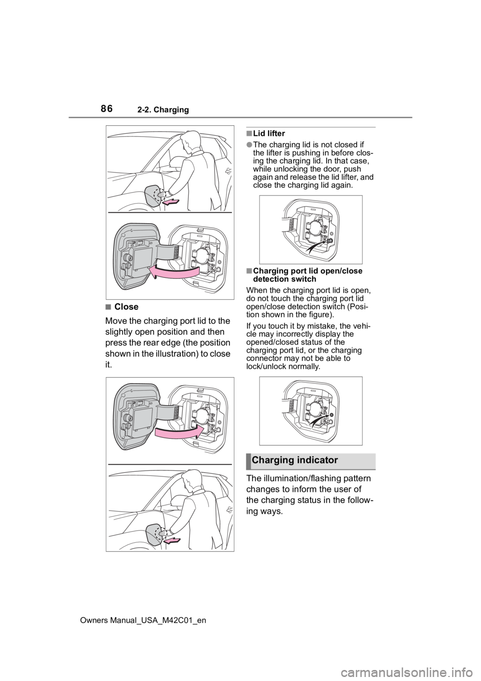
■Close
Move the charging port lid to the
slightly open position and then
press the rear edge (the position
shown in the illustration) to close
it.
■Lid lifter
●The charging lid is not closed if
the lifter is pushing in before clos-
ing the charging lid. In that case,
while unlocking the door, push
again and release the lid lifter, and
close the charging lid again.
■Charging port lid open/close
detection switch
When the charging port lid is open,
do not touch the charging port lid
open/close detection switch (Posi-
tion shown in the figure).
If you touch it by mistake, the vehi-
cle may incorrectly display the
opened/closed status of the
charging port lid, or the charging
connector may not be able to
lock/unlock normally.
The illumination/flashing pattern
changes to inform the user of
the charging status in the follow-
ing ways.
Charging indicator
Page 93 of 628
932-2. Charging
Owners Manual_USA_M42C01_en
2
Electric Vehicle system
■Locking the charging con-
nector
The AC charging connector will
be automatically locked when
inserting it into the AC charging
inlet.
(The setting can be
changed: P.93)
■Unlocking the charging
connector
The AC charging connector will
be unlocked when the doors are
unlocked using the smart key
system or wireless remote con-
trol.
The AC charging connector
locks when connected and
unlocks when the door is
unlocked, so locking/unlocking
the AC charging connector does
not necessarily correspond to
locking/unlocking the door. If the door is unlocked and the
AC charging connector is
locked, you can unlock it by
doing the following:
• When using the smart key
system, lock the door once
and then unlock it again.
( P.167)
• When using the wireless remote control, press the
unlock button to unlock the
door. ( P.167)
■Changing the AC charging
connector lock settings
The method for locking and
unlocking the AC charging con-
nector can be changed on the
multi-information display or mul-
timedia.
The charging connector lock
settings cannot be changed
when the AC charging cable is
connected to the vehicle.
The settings cannot be changed
when the power switch is in
ACC.
Multi-information display
operation
1 Press or of the meter
control switches to select
.
2 Press or of the meter
control switches to select
“Vehicle Settings”, and then
press and hold .
Locking and unlock-
ing AC charging con-
nector
The AC charging connector
will be locked when it is
connected to the AC
charging inlet, preventing
the AC charging cable from
being disconnected while
charging.
Locking and unlocking
the AC charging connec-
tor
Page 95 of 628
952-2. Charging
Owners Manual_USA_M42C01_en
2
Electric Vehicle system
■AC charging connector lock
function
If the AC charging connector is
locked/unlocked repeatedly, it may
not work temporarily due to protect
the system by AC charging system.
In this case, wait for a while before
connecting the AC charging connec-
tor to AC charging inlet again.
The AC charging connector lock
function does not guarantee that
theft of the AC charging cable will be
prevented, and is not necessarily
effective for all mischiefs.
■Security function for unlocking
If the AC charging connector is not
removed within approximately 30
seconds after the vehicle is
unlocked, the secur ity function auto-
matically locks the connector again.
■When the AC charging connec-
tor cannot be inserted into the
AC charging inlet
If the connector lock pin is
extended, the connector lock is
operating.
Unlock the doors using the smart
key system or wireless remote con-
trol and unlock the AC charging con-
nector lock and check that the
connector lock pin is not extended.
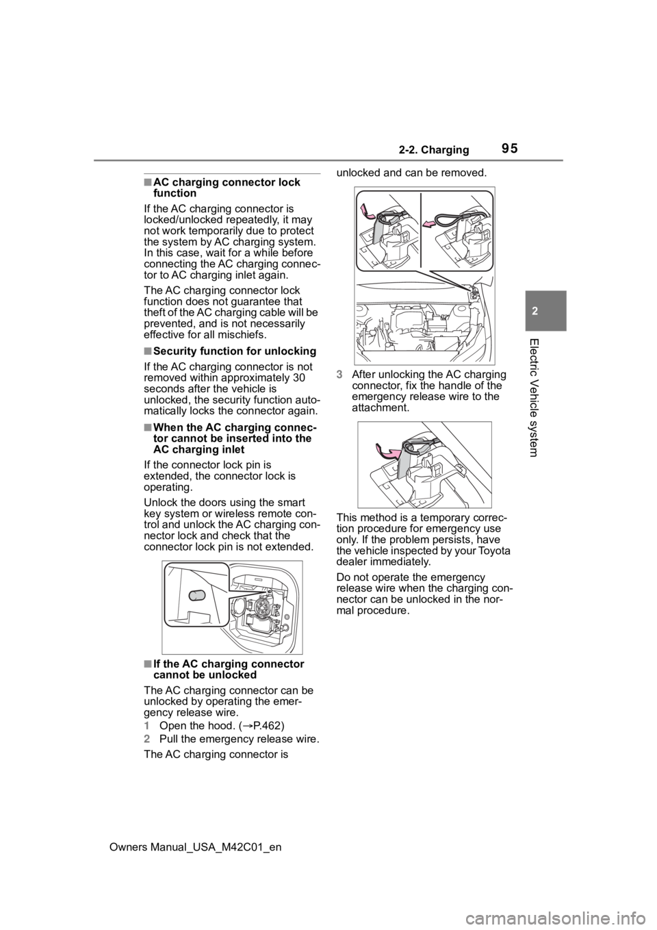
■If the AC charging connector
cannot be unlocked
The AC charging connector can be
unlocked by operating the emer-
gency release wire.
1 Open the hood. ( P.462)
2 Pull the emergency release wire.
The AC charging connector is unlocked and can be removed.
3
After unlocking the AC charging
connector, fix the handle of the
emergency release wire to the
attachment.
This method is a temporary correc-
tion procedure for emergency use
only. If the problem persists, have
the vehicle inspected by your Toyota
dealer immediately.
Do not operate the emergency
release wire when the charging con-
nector can be unlocked in the nor-
mal procedure.
Page 96 of 628
962-2. Charging
Owners Manual_USA_M42C01_en
Connect to an AC 120 V out-
let (NEMA 5-15R) with a
Ground-Fault Circuit-Inter-
rupter (GFCI) and a circuit
breaker. Use of a 15A individ-
ual circuit is strongly recom-
mended to ensure AC
charging cable will operate
properly.
When charging outdoors,
make sure to connect to a
weatherproof outlet that is
certified for outdoor use.
Checking Ground-Fault Cir-
cuit-Interrupter (GFCI) opera-
tion before its use is
recommended.
WARNING
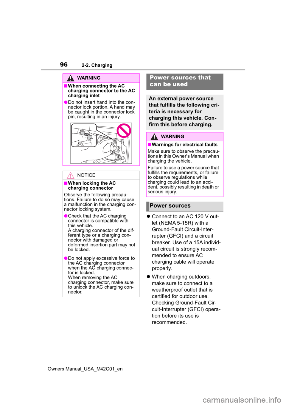
■When connecting the AC
charging connector to the AC
charging inlet
●Do not insert hand into the con-
nector lock portion. A hand may
be caught in the connector lock
pin, resulting in an injury.
NOTICE
■When locking the AC
charging connector
Observe the following precau-
tions. Failure to do so may cause
a malfunction in the charging con-
nector locking system.
●Check that the AC charging
connector is compatible with
this vehicle.
A charging connector of the dif-
ferent type or a charging con-
nector with damaged or
deformed insertion part may not
be locked.
●Do not apply excessive force to
the AC charging connector
when the AC charging connec-
tor is locked.
When removing the AC
charging connector, make sure
to unlock the AC charging con-
nector.
Power sources that
can be used
An external power source
that fulfills the following cri-
teria is necessary for
charging this vehicle. Con-
firm this before charging.
WARNING
■Warnings for electrical faults
Make sure to observe the precau-
tions in this Owner’s Manual when
charging the vehicle.
Failure to use a power source that
fulfills the requirements, or failure
to observe regulations while
charging could lead to an acci-
dent, possibly resulting in death or
serious injury.
Power sources
Page 111 of 628
1112-2. Charging
Owners Manual_USA_M42C01_en
2
Electric Vehicle system
1 Unlock the doors to unlock
the charging connector.
( P.93)
The charging connector will be
unlocked and the AC charging inlet
light will illuminate when the doors
are unlocked.
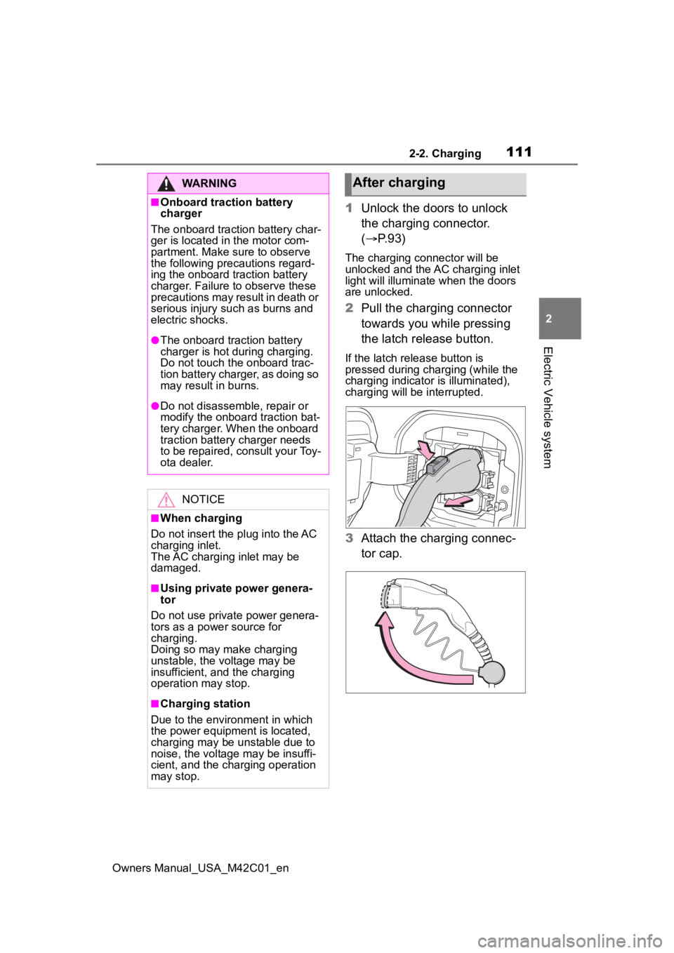
2Pull the charging connector
towards you while pressing
the latch release button.
If the latch release button is
pressed during charging (while the
charging indicator is illuminated),
charging will be interrupted.
3 Attach the charging connec-
tor cap.
WARNING
■Onboard traction battery
charger
The onboard traction battery char-
ger is located in the motor com-
partment. Make sure to observe
the following precautions regard-
ing the onboard traction battery
charger. Failure to observe these
precautions may result in death or
serious injury suc h as burns and
electric shocks.
●The onboard traction battery
charger is hot during charging.
Do not touch the onboard trac-
tion battery charger, as doing so
may result in burns.
●Do not disassemble, repair or
modify the onboard traction bat-
tery charger. When the onboard
traction battery charger needs
to be repaired, consult your Toy-
ota dealer.
NOTICE
■When charging
Do not insert the p lug into the AC
charging inlet.
The AC charging inlet may be
damaged.
■Using private power genera-
tor
Do not use private power genera-
tors as a power source for
charging.
Doing so may make charging
unstable, the voltage may be
insufficient, and the charging
operation may stop.
■Charging station
Due to the environment in which
the power equipme nt is located,
charging may be unstable due to
noise, the voltage may be insuffi-
cient, and the charging operation
may stop.
After charging
Page 112 of 628
1122-2. Charging
Owners Manual_USA_M42C01_en
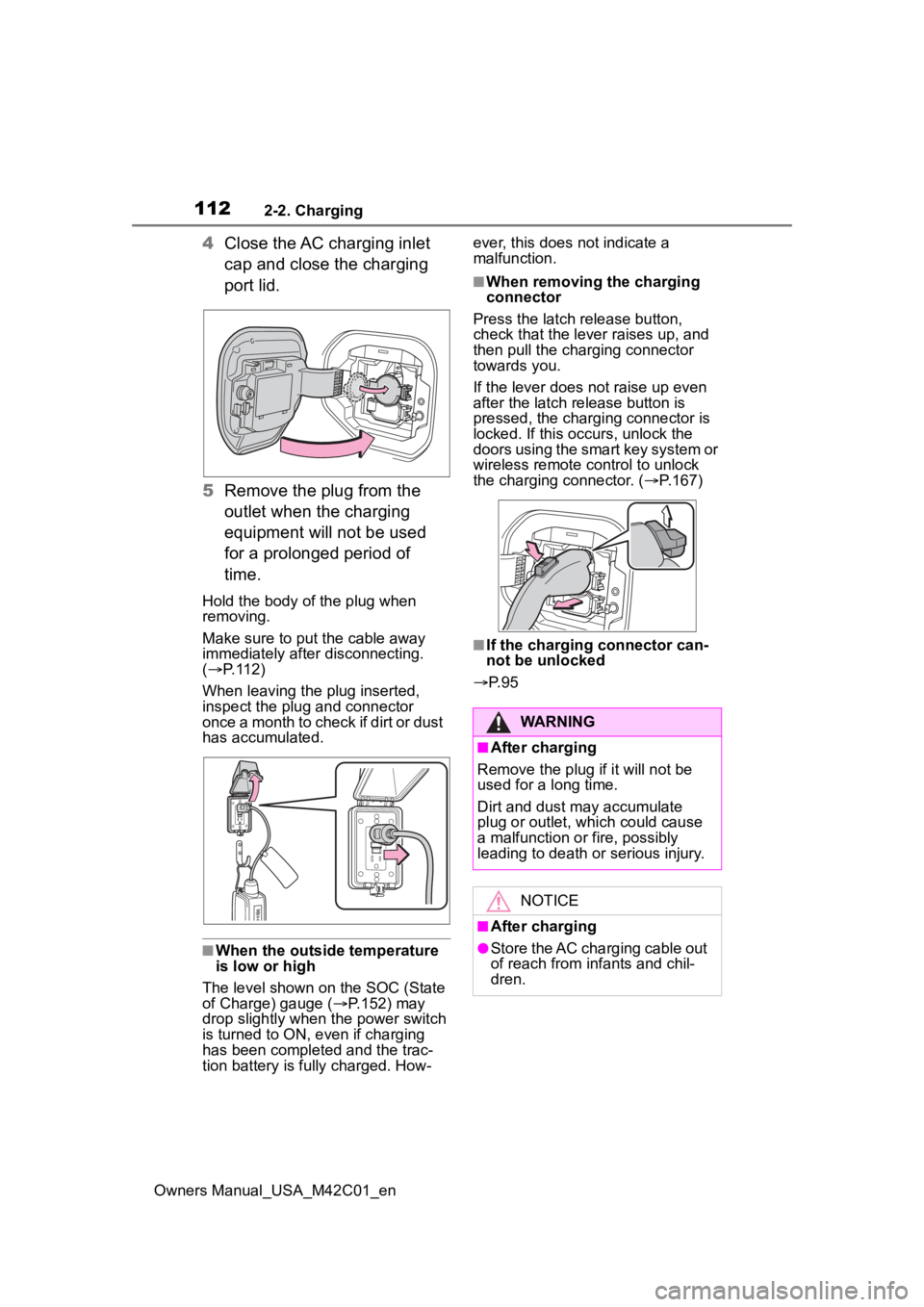
4Close the AC charging inlet
cap and close the charging
port lid.
5 Remove the plug from the
outlet when the charging
equipment will not be used
for a prolonged period of
time.
Hold the body of the plug when
removing.
Make sure to put the cable away
immediately afte r disconnecting.
( P. 1 1 2 )
When leaving the plug inserted,
inspect the plug and connector
once a month to check if dirt or dust
has accumulated.
■When the outside temperature
is low or high
The level shown on the SOC (State
of Charge) gauge ( P.152) may
drop slightly when the power switch
is turned to ON, e ven if charging
has been completed and the trac-
tion battery is fully charged. How- ever, this does not indicate a
malfunction.
■When removing the charging
connector
Press the latch release button,
check that the lever raises up, and
then pull the charging connector
towards you.
If the lever does not raise up even
after the latch release button is
pressed, the charging connector is
locked. If this occurs, unlock the
doors using the smart key system or
wireless remote control to unlock
the charging connector. ( P.167)
■If the charging connector can-
not be unlocked
P. 9 5
WARNING
■After charging
Remove the plug if it will not be
used for a long time.
Dirt and dust may accumulate
plug or outlet, which could cause
a malfunction or fire, possibly
leading to death or serious injury.
NOTICE
■After charging
●Store the AC charging cable out
of reach from infants and chil-
dren.