load capacity TOYOTA BZ4X 2023 Owners Manual
[x] Cancel search | Manufacturer: TOYOTA, Model Year: 2023, Model line: BZ4X, Model: TOYOTA BZ4X 2023Pages: 628, PDF Size: 11.91 MB
Page 104 of 628

1042-2. Charging
Owners Manual_USA_M42C01_en
●Avoid frequent DC charging
Also, if the capacit y of the traction
battery capacity reduces, the dis-
tance that can be driven decreases.
However, vehicle performance does
not significantly become worse.
■When the remaining charge of
the traction battery is low after
charging
In the following situations, the
remaining charge of the traction bat-
tery after charging completes may
be less than normal in order to pro-
tect the traction bat tery (the driving
range after the battery is fully
charged may be shorter).
*
●Charging is perf ormed when the
outside temperature is low or high
●Charging is perf ormed immedi-
ately after high-l oad driving or in
extreme heat
In any other situati on, if the remain-
ing charge of the traction battery is
significantly lower than normal after
charging completes, have the vehi-
cle inspected by your Toyota dealer.
*: When this occurs, even if the remaining charge display of the
traction battery shows that it is
fully charged, the remaining
charge rapidly decreases faster
than normal.
■When the charging amount sent
to the traction battery
decreases
When the amount of power supplied
by the charger is low or operation of
the battery heater, etc., reduces the
charging power sent to the traction
battery, the charging amount sent to
the traction battery may decrease.
■Certification
This device complies with Part 15 of
the FCC Rules. Operation is subject
to the following two conditions:
(1) this device may not cause harm- ful interference, and (2) this device
must accept any interference
received, including interference that
may cause undesired operation.
■Charging time may increase
In the following situ ations, charging
time may become longer than nor-
mal:
●In very hot or very cold tempera-
tures.
●When the traction battery
becomes hot, such as immedi-
ately after high-load driving.
●The vehicle is consuming a lot of
electricity, for e xample, when the
headlights are on, etc.
●When using “My Room Mode”.
( P.129)
●There is a power outage during
charging.
●There is an interruption in the
electrical supply.
●There is a drop in the voltage of
external power source.
●The charge in the 12-volt battery
is low, for example due to the
vehicle being left unused for a
long period of time.
●When the upper limit of charging
current is changed in the charging
current setting of the vehicle
( P.108)
●When the battery heater operates.
( P. 9 9 )
●When the “Battery Cooler” is oper-
ated before charging. ( P. 9 9 )
●When the plug generates heat
due to a loose outlet connection,
etc.
●When adjusting the power supply
with the charger.
●When frequently and repeatedly
using DC charging.
●When selecting “DC charging
power” setting other than “MAX”.
●When the temperature of
charging-related parts is high.
Page 226 of 628
2265-1. Before driving
Owners Manual_USA_M42C01_en
Cargo capacity depends on the
total weight of the occupants.
(Cargo capacity) = (Total load
capacity) - (Total weight of occu-
pants)
Steps for Determining Cor-
rect Load Limit
(1) Locate the statement “The
combined weight of occupants
and cargo should never exceed
XXX kg or XXX lbs.” on your
vehicle’s placard.
(2) Determine the combined
weight of the driver and passen-
gers that will be riding in your
vehicle.
(3) Subtract the combined
weight of the driver and passen-
gers from XXX kg or XXX lbs.
(4) The resulting figure equals
the available amount of cargo
and luggage load capacity. For example, if the “XXX”
amount equals 1400 lbs. and
there will be five 150 lb passen-
gers in your vehicle, the amount
of available cargo and luggage
load capacity is 650 lbs. (1400 -
750 (5
150) = 650 lbs.)
(5) Determine the combined
weight of luggage and cargo
being loaded on the vehicle.
That weight may not safely
exceed the available cargo and
luggage load capacity calcu-
lated in Step 4.
(6) If your vehicle will be towing
a trailer, load from your trailer
will be transferred to your vehi-
cle. Consult this manual to
determine how this reduces the
available cargo and luggage
load capacity of your vehicle.
( P.228)
WARNING
�
Page 227 of 628
2275-1. Before driving
Owners Manual_USA_M42C01_en
5
Driving
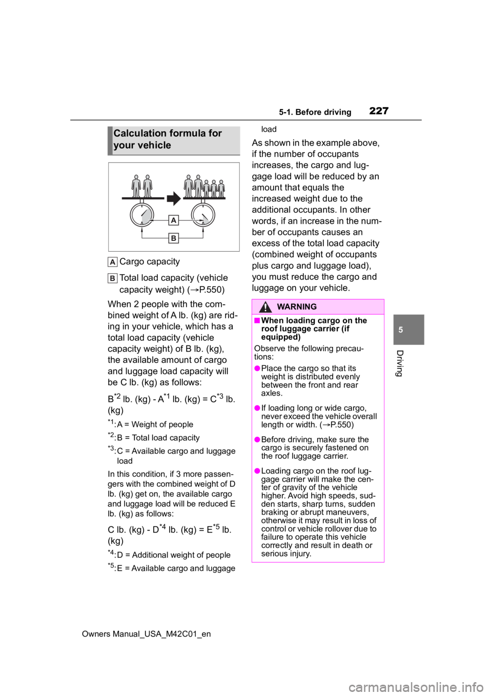
Cargo capacity
Total load capacity (vehicle
capacity weight) ( P.550)
When 2 people with the com-
bined weight of A lb. (kg) are rid-
ing in your vehicle, which has a
total load capacity (vehicle
capacity weight) of B lb. (kg),
the available amount of cargo
and luggage load capacity will
be C lb. (kg) as follows:
B
*2 lb. (kg) - A*1 lb. (kg) = C*3 lb.
(kg)
*1: A = Weight of people
*2: B = Total load capacity
*3: C = Available cargo and luggage load
In this condition, if 3 more passen-
gers with the combined weight of D
lb. (kg) get on, the available cargo
and luggage load will be reduced E
lb. (kg) as follows:
C lb. (kg) - D*4 lb. (kg) = E*5 lb.
(kg)
*4: D = Additional weight of people
*5: E = Available cargo and luggage load
As shown in the example above,
if the number of occupants
increases, the cargo and lug-
gage load will be reduced by an
amount that equals the
increased weight due to the
additional occupants. In other
words, if an increase in the num-
ber of occupants causes an
excess of the total load capacity
(combined weight of occupants
plus cargo and luggage load),
you must reduce the cargo and
luggage on your vehicle.
Calculation formula for
your vehicle
WARNING
■When loading cargo on the
roof luggage carrier (if
equipped)
Observe the following precau-
tions:
●Place the cargo so that its
weight is distributed evenly
between the front and rear
axles.
●If loading long or wide cargo,
never exceed the vehicle overall
length or width. ( P.550)
●Before driving, m ake sure the
cargo is securely fastened on
the roof luggage carrier.
●Loading cargo on the roof lug-
gage carrier will make the cen-
ter of gravity of the vehicle
higher. Avoid high speeds, sud-
den starts, sharp turns, sudden
braking or abrupt maneuvers,
otherwise it may result in loss of
control or vehicle rollover due to
failure to operate this vehicle
correctly and result in death or
serious injury.
Page 228 of 628
2285-1. Before driving
Owners Manual_USA_M42C01_en
■Total load capacity and seating
capacity
These details are also described on
the tire and loading information
label. ( P.491)
WARNING
●If driving for a long distance, on
rough roads, or at high speeds,
stop the vehicle now and then
during the trip to make sure the
cargo remains in its place.
●Do not exceed 165.3 lb. (75 kg)
cargo weight on the roof lug-
gage carrier.
NOTICE
■When loading cargo on the
roof luggage carrier (if
equipped)
Be careful not to scratch the sur-
face of the panoramic moon roof
(if equipped).
Vehicle load limits
Vehicle load limits include
total load capacity, seating
capacity, TWR (Trailer
Weight Rating) and cargo
capacity.
Total load capacity (vehicle
capacity weight): P.550
Total load capacity means the
combined weight of occu-
pants, cargo and luggage.
Seating capacity: P.550
Seating capacity means the
maximum number of occu-
pants whose estimated aver-
age weight is 150 lb. (68 kg)
per person.
TWR (Trailer Weight Rat-
ing)
Toyota does not recommend
towing a trailer with your vehi-
cle.
Cargo capacity
Cargo capacity may increase
or decrease depending on the
weight and the number of
occupants.
Page 391 of 628
3915-4. Using the driving support systems
Owners Manual_USA_M42C01_en
5
Driving
WARNING
●Unlike the parking brake, hill-
start assist control is not
intended to hold the vehicle sta-
tionary for an extended period
of time. Do not attempt to use
hill-start assist control to hold
the vehicle on an incline, as
doing so may lead to an acci-
dent.
■When the
TRAC/ABS/VSC/Trailer Sway
Control is activated
The slip indicator light flashes.
Always drive carefully. Reckless
driving may cause an accident.
Exercise particular care when the
indicator light flashes.
■When the TRAC/VSC/Trailer
Sway Control systems are
turned off
Be especially careful and drive at
a speed appropriate to the road
conditions. As these are the sys-
tems to help ensure vehicle stabil-
ity and driving force, do not turn
the TRAC/VSC/Trailer Sway Con-
trol systems off unless necessary.
Trailer Sway Control is part of the
VSC system and will not operate
if VSC is turned off or experiences
a malfunction.
■Replacing tires
Make sure that all tires are of the
specified size, brand, tread pat-
tern and total load capacity. In
addition, make sure that the tires
are inflated to the recommended
tire inflation pressure level.
The ABS, TRAC, VSC and Trailer
Sway Control systems will not
function correctly if different tires
are installed on the vehicle.
Contact your Toyota dealer for fur-
ther information when replacing
tires or wheels.
■Handling of tires and the sus-
pension
Using tires with any kind of prob-
lem or modifying the suspension
will affect the driving assist sys-
tems, and may cause a system to
malfunction.
■Trailer Sway Control precau-
tion
The Trailer Sway Control system
is not able to red uce trailer sway
in all situations. Depending on
many factors such as the condi-
tions of the vehicle, trailer, road
surface and driving environment,
the Trailer Sway Control system
may not be effective. Refer to
your trailer owner’s manual for
information on how to tow your
trailer properly.
■If trailer sway occurs
Observe the following precau-
tions.
Failing to do so may cause death
or serious injury.
●Firmly grip the steering wheel.
Steer straight ahead. Do not try
to control trailer swaying by
turning the steering wheel.
●Begin releasing the accelerator
pedal immediately but very
gradually to reduce speed.
Do not increase speed. Do not
apply vehicle brakes.
If you make no extreme correction
with the steering or brakes, your
vehicle and traile r should stabi-
lize. ( P.229)
Page 473 of 628
4737-3. Do-it-yourself maintenance
Owners Manual_USA_M42C01_en
7
Maintenance and care
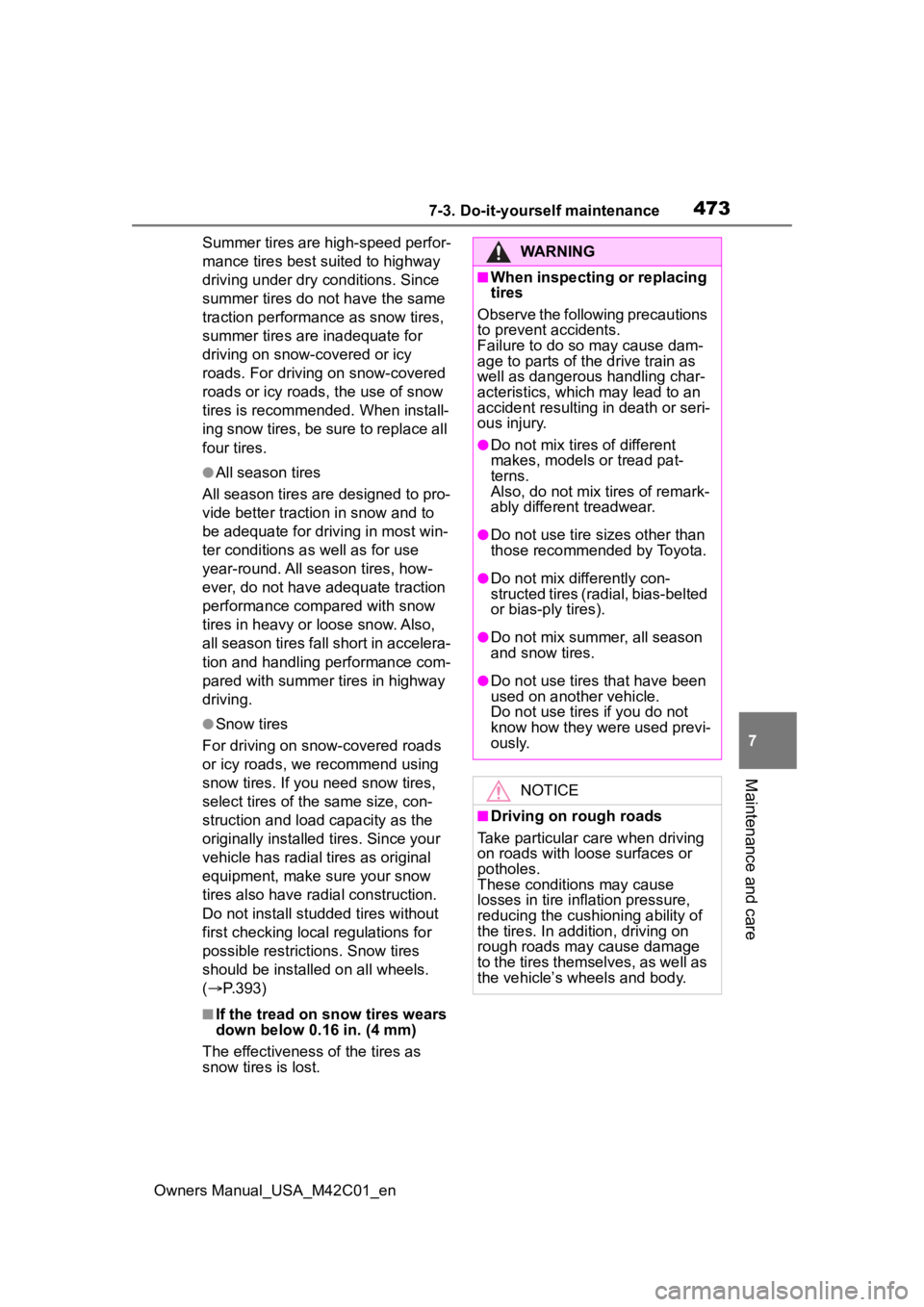
Summer tires are high-speed perfor-
mance tires best suited to highway
driving under dry conditions. Since
summer tires do not have the same
traction performanc e as snow tires,
summer tires are inadequate for
driving on snow-covered or icy
roads. For driving on snow-covered
roads or icy roads, the use of snow
tires is recommended. When install-
ing snow tires, be sure to replace all
four tires.
●All season tires
All season tires are designed to pro-
vide better traction in snow and to
be adequate for driving in most win-
ter conditions a s well as for use
year-round. All season tires, how-
ever, do not have adequate traction
performance compared with snow
tires in heavy or loose snow. Also,
all season tires fall short in accelera-
tion and handling performance com-
pared with summer tires in highway
driving.
●Snow tires
For driving on snow-covered roads
or icy roads, we recommend using
snow tires. If you need snow tires,
select tires of the same size, con-
struction and load capacity as the
originally installed tires. Since your
vehicle has radial tires as original
equipment, make sure your snow
tires also have radial construction.
Do not install stud ded tires without
first checking local regulations for
possible restrictions. Snow tires
should be installed on all wheels.
( P.393)
■If the tread on snow tires wears
down below 0.16 in. (4 mm)
The effectiveness of the tires as
snow tires is lost.
WARNING
■When inspecting or replacing
tires
Observe the following precautions
to prevent accidents.
Failure to do so may cause dam-
age to parts of the drive train as
well as dangerous handling char-
acteristics, which may lead to an
accident resulting in death or seri-
ous injury.
●Do not mix tires of different
makes, models or tread pat-
terns.
Also, do not mix tires of remark-
ably different treadwear.
●Do not use tire sizes other than
those recommended by Toyota.
●Do not mix differently con-
structed tires (radial, bias-belted
or bias-ply tires).
●Do not mix summer, all season
and snow tires.
●Do not use tires that have been
used on another vehicle.
Do not use tires if you do not
know how they were used previ-
ously.
NOTICE
■Driving on rough roads
Take particular care when driving
on roads with loose surfaces or
potholes.
These conditions may cause
losses in tire inflation pressure,
reducing the cushioning ability of
the tires. In addition, driving on
rough roads may cause damage
to the tires themselves, as well as
the vehicle’s wheels and body.
Page 493 of 628
4937-3. Do-it-yourself maintenance
Owners Manual_USA_M42C01_en
7
Maintenance and care
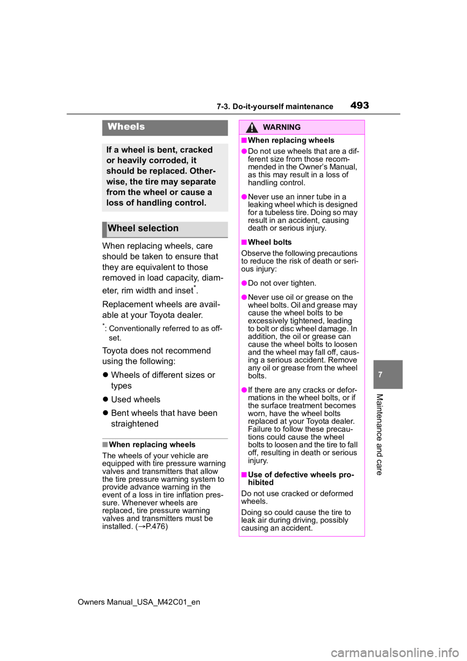
When replacing wheels, care
should be taken to ensure that
they are equivalent to those
removed in load capacity, diam-
eter, rim width and inset
*.
Replacement wheels are avail-
able at your Toyota dealer.
*: Conventionally referred to as off- set.
Toyota does not recommend
using the following:
Wheels of different sizes or
types
Used wheels
Bent wheels that have been
straightened
■When replacing wheels
The wheels of your vehicle are
equipped with tire pressure warning
valves and transmitters that allow
the tire pressure warning system to
provide advance warning in the
event of a loss in tire inflation pres-
sure. Whenever wheels are
replaced, tire pressure warning
valves and transmitters must be
installed. ( P.476)
Wheels
If a wheel is bent, cracked
or heavily corroded, it
should be replaced. Other-
wise, the tire may separate
from the wheel or cause a
loss of handling control.
Wheel selection
WARNING
■When replacing wheels
●Do not use wheels that are a dif-
ferent size from those recom-
mended in the Owner’s Manual,
as this may result in a loss of
handling control.
●Never use an inner tube in a
leaking wheel which is designed
for a tubeless tire. Doing so may
result in an accident, causing
death or serious injury.
■Wheel bolts
Observe the following precautions
to reduce the risk of death or seri-
ous injury:
●Do not over tighten.
●Never use oil or grease on the
wheel bolts. Oil and grease may
cause the wheel bolts to be
excessively tightened, leading
to bolt or disc wheel damage. In
addition, the oil or grease can
cause the wheel bolts to loosen
and the wheel may fall off, caus-
ing a serious accident. Remove
any oil or grease from the wheel
bolts.
●If there are any cracks or defor-
mations in the wheel bolts, or if
the surface treatment becomes
worn, have the wheel bolts
replaced at your Toyota dealer.
Failure to follow these precau-
tions could cause the wheel
bolts to loosen and the tire to fall
off, resulting in death or serious
injury.
■Use of defective wheels pro-
hibited
Do not use cracke d or deformed
wheels.
Doing so could cause the tire to
leak air during driving, possibly
causing an accident.
Page 560 of 628
5609-1. Specifications
Owners Manual_USA_M42C01_enheat buildup and possible tire fail- ure.
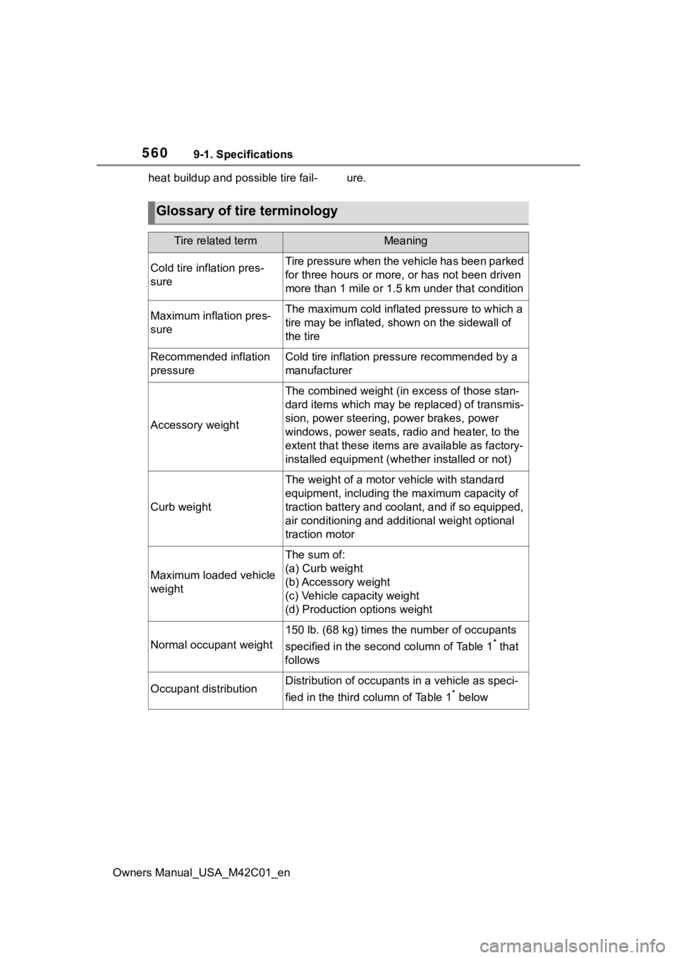
Glossary of tire terminology
Tire related termMeaning
Cold tire inflation pres-
sureTire pressure when the vehicle has been parked
for three hours or more, or has not been driven
more than 1 mile or 1.5 km under that condition
Maximum inflation pres-
sureThe maximum cold inflated pressure to which a
tire may be inflated, shown on the sidewall of
the tire
Recommended inflation
pressureCold tire inflation pressure recommended by a
manufacturer
Accessory weight
The combined weight (in
excess of those stan-
dard items which may be replaced) of transmis-
sion, power steering, power brakes, power
windows, power seats, radio and heater, to the
extent that these items are available as factory-
installed equipment (whether installed or not)
Curb weight
The weight of a motor vehicle with standard
equipment, including th e maximum capacity of
traction battery and coolant, and if so equipped,
air conditioning and additional weight optional
traction motor
Maximum loaded vehicle
weight
The sum of:
(a) Curb weight
(b) Accessory weight
(c) Vehicle capacity weight
(d) Production options weight
Normal occupant weight
150 lb. (68 kg) times the number of occupants
specified in the second column of Table 1
* that
follows
Occupant distributionDistribution of occupant s in a vehicle as speci-
fied in the third column of Table 1
* below
Page 561 of 628
5619-1. Specifications
Owners Manual_USA_M42C01_en
9
Vehicle specifications
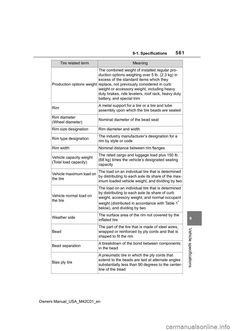
Production options weight
The combined weight of installed regular pro-
duction options weighing over 5 lb. (2.3 kg) in
excess of the standard items which they
replace, not previously considered in curb
weight or accessory weight, including heavy
duty brakes, ride leveler s, roof rack, heavy duty
battery, and special trim
RimA metal support for a ti re or a tire and tube
assembly upon which the tire beads are seated
Rim diameter
(Wheel diameter)Nominal diameter o f the bead seat
Rim size designationRim diameter and width
Rim type designationThe industry manufacture r’s designation for a
rim by style or code
Rim widthNominal distance between rim flanges
Vehicle capacity weight
(Total load capacity)The rated cargo and luggage load plus 150 lb.
(68 kg) times the vehicl e’s designated seating
capacity
Vehicle maximum load on
the tireThe load on an individual tire that is determined
by distributing to each ax le its share of the max-
imum loaded vehicle weight, and dividing by two
Vehicle normal load on
the tire
The load on an individual tire that is determined
by distributing to each axle its share of curb
weight, accessory weight, and normal occupant
weight (distributed in accordance with Table 1
*
below), and dividing by two
Weather sideThe surface area of the rim not covered by the
inflated tire
Bead
The part of the tire that is made of steel wires,
wrapped or reinforced by ply cords and that is
shaped to fit the rim
Bead separationA breakdown of the bond between components
in the bead
Bias ply tire
A pneumatic tire in which the ply cords that
extend to the beads are la id at alternate angles
substantially less than 9 0 degrees to the center-
line of the tread
Tire related termMeaning
Page 564 of 628

5649-1. Specifications
Owners Manual_USA_M42C01_en
*: Table 1 Occupant loading and distribution for vehicle normal load for
various designated seating capacities
SidewallThat portion of a tire between the tread and
bead
Sidewall separationThe parting of the rubber compound from the
cord material in the sidewall
Snow tire
A tire that attains a tra ction index equal to or
greater than 110, compared to the ASTM E-
1136 Standard Reference Test Tire, when using
the snow traction test a s described in ASTM F-
1805-00, Standard Test Method for Single
Wheel Driving Traction in a Straight Line on
Snow-and Ice-Covered Su rfaces, and which is
marked with an Alpine Symbol ( ) on at least
one sidewall
Test rim
The rim on which a tire is fitted for testing, and
may be any rim listed as appropriate for use
with that tire
TreadThat portion of a tire t hat comes into contact
with the road
Tread ribA tread section running circumferentially around
a tire
Tread separationPulling away of the tread from the tire carcass
Treadwear indicators
(TWI)The projections within the principal grooves
designed to give a visual indication of the
degrees of wear of the tread
Wheel-holding fixtureThe fixture used to hold the wheel and tire
assembly securely during testing
Designated seating
capacity, Number of occupantsVehicle normal load,
Number of occupantsOccupant distribution in a normally loaded vehi- cle
2 through 422 in front
5 through 1032 in front, 1 in second
seat
Tire related termMeaning