TOYOTA C-HR 2018 1.G Owners Manual
Manufacturer: TOYOTA, Model Year: 2018, Model line: C-HR, Model: TOYOTA C-HR 2018 1.GPages: 516, PDF Size: 9.32 MB
Page 251 of 516
2514-5. Using the driving support systems
4
Driving
C-HR_OM_USA_OM10526U
Driving mode select
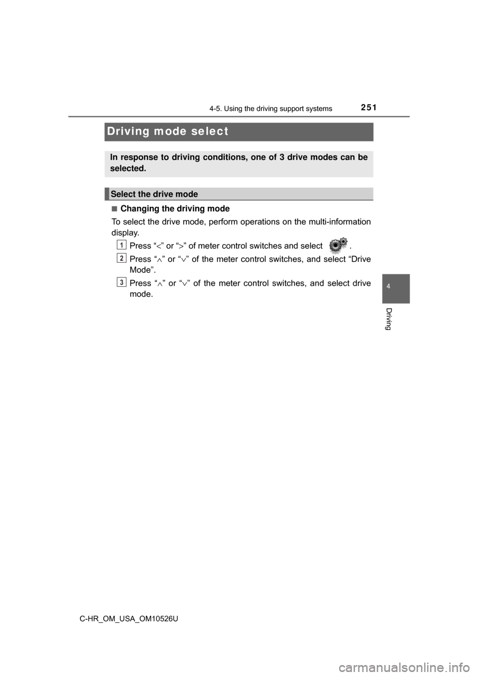
■Changing the driving mode
To select the drive mode, perform operations on the multi-information
display.
Press “ <” or “>” of meter control sw itches and select .
Press “ ∧” or “ ∨” of the meter control switches, and select “Drive
Mode”.
Press “ ∧” or “∨ ” of the meter control switches, and select drive
mode.
In response to driving conditions, one of 3 drive modes can be
selected.
Select the drive mode
1
2
3
Page 252 of 516
2524-5. Using the driving support systems
C-HR_OM_USA_OM10526U■
Driving modes
●
“NORMAL” mode
Provides an optimal balance of fuel economy, quietness, and
dynamic performance. Suitable for city driving.
● “SPORT” mode
Controls the transmission and engine to provide quick, powerful
acceleration. This mode also c hanges the steering feel, making it
suitable for when agile driving response is desired, such as when
driving on roads with many curves.
When sport mode is selected, the “SPORT” indicator will illuminate
on the multi-information display.
● “ECO” mode
Helps the driver accelerate in an eco-friendly manner and
improve fuel economy through moderate throttle characteristics
and by controlling the operation of the air conditioning system
(heating/cooling).
When Eco mode is selected, the “ECO MODE” indicator will illumi-
nate on the multi-information display.
While the air conditioning is being used, the system automatically
switches to air conditioning eco mode ( →P. 295), allowing for driving
that leads to even better fuel economy.
■ Canceling driving modes
●Select another drive mode. Also, “SPORT” mode will be canceled automati-
cally when the engine switch is turned off.
● “NORMAL” mode and “ECO” mode will not be canceled automatically until
another drive mode is selected, even if the engine switch is turned off.
Page 253 of 516
2534-5. Using the driving support systems
4
Driving
C-HR_OM_USA_OM10526U
BSM (Blind Spot Monitor)∗
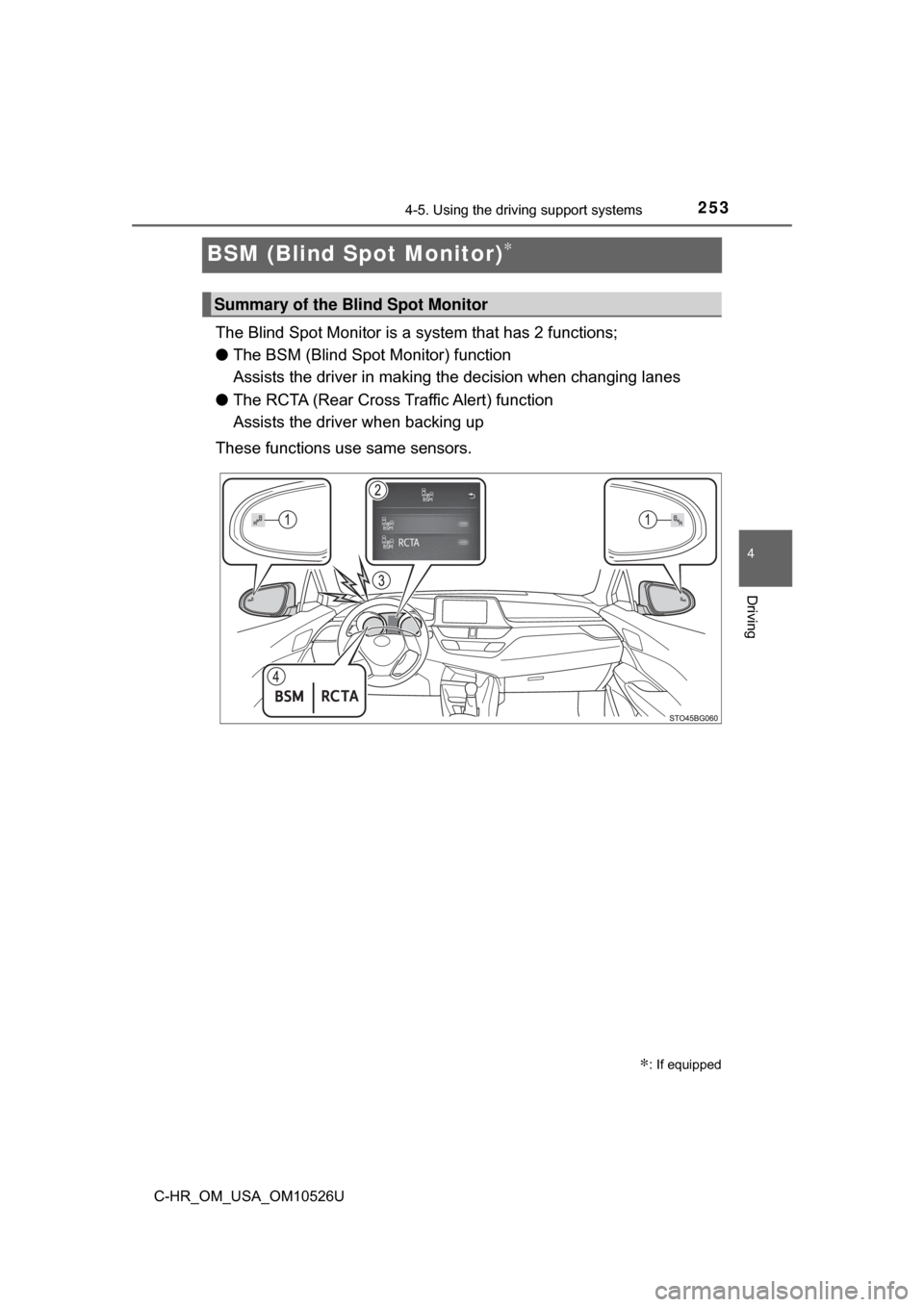
The Blind Spot Monitor is a system that has 2 functions;
● The BSM (Blind Spot Monitor) function
Assists the driver in making t he decision when changing lanes
● The RCTA (Rear Cross Traffic Alert) function
Assists the driver when backing up
These functions use same sensors.
∗: If equipped
Summary of the Blind Spot Monitor
Page 254 of 516
2544-5. Using the driving support systems
C-HR_OM_USA_OM10526U
Outside rear view mirror indicators
BSM function:
When a vehicle is detected in a blind spot of the outside rear view mirrors
or approaching rapidly from behind into a blind spot, the outside rear view
mirror indicator on the detected side will illuminate. If the turn signal lever
is operated toward the detected side, the outside rear view mirror indicator
will flash.
RCTA function:
When a vehicle approaching from the right or left at the rear of the vehicle
is detected, both outside rear view mirror indicators will flash.
Multi-information display
Turning the BSM function/RCTA function on/off. ( →P. 255)
The RCTA function is available when the BSM function is on.
RCTA buzzer (RCTA function only)
If a vehicle approaching from the right or left at the rear of the vehic\
le is
detected, a buzzer will sound. The buzzer also sounds for approximately
1 second immediately after the BSM function is operated to turn the sys-
tem on.
“BSM” indicator/“RCTA” indicator
When the BSM function/RCTA function is turned on, the indicator illumi-
nates.
Page 255 of 516
2554-5. Using the driving support systems
4
Driving
C-HR_OM_USA_OM10526U
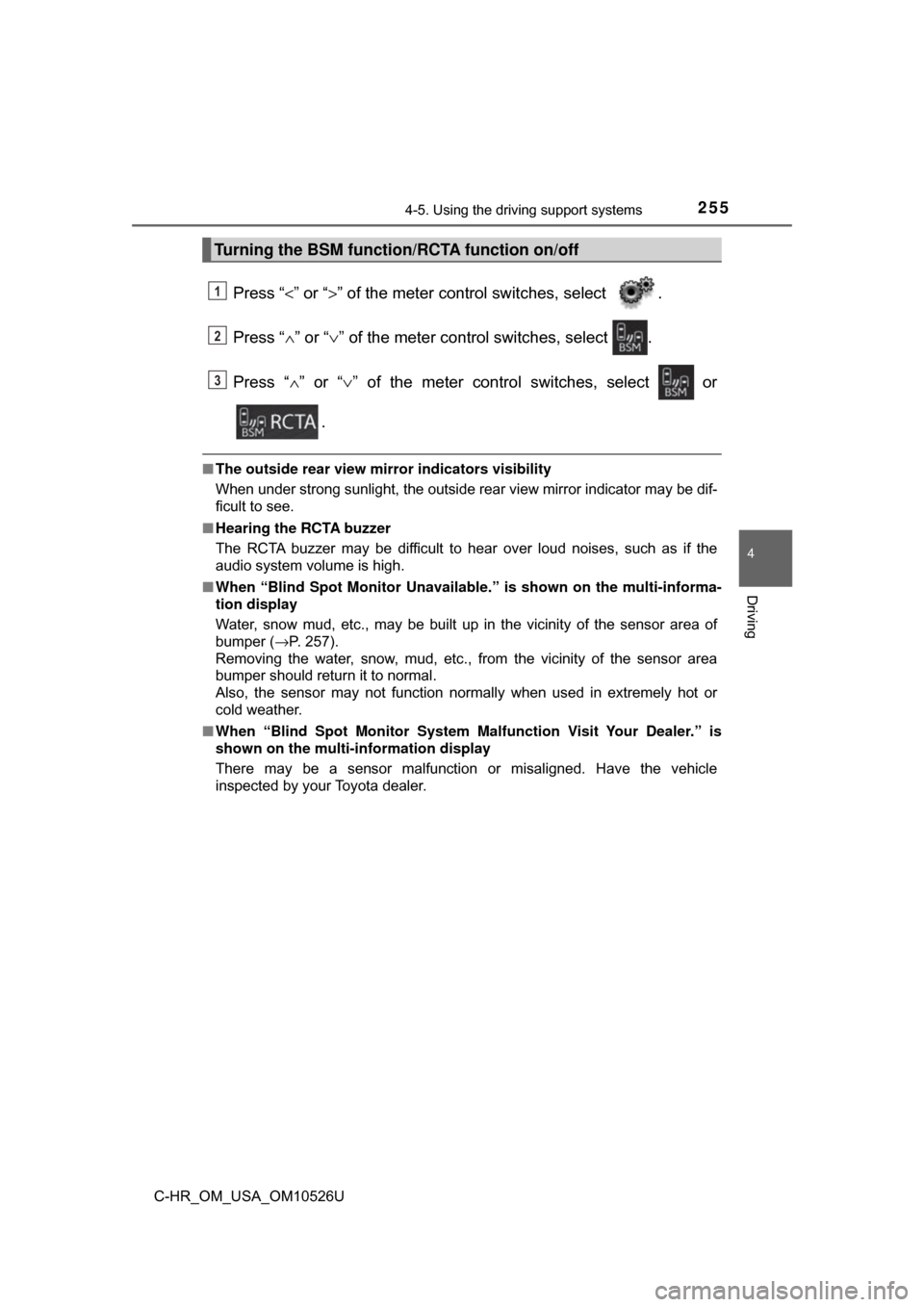
Press “<” or “>” of the meter contro l switches, select .
Press “ ∧” or “ ∨” of the meter control switches, select .
Press “ ∧” or “ ∨” of the meter control switches, select or
.
■ The outside rear view mirror indicators visibility
When under strong sunlight, the outside rear view mirror indicator may be dif-
ficult to see.
■ Hearing the RCTA buzzer
The RCTA buzzer may be difficult to hear over loud noises, such as if the
audio system volume is high.
■ When “Blind Spot Moni tor Unavailable.” is shown on the multi-informa-
tion display
Water, snow mud, etc., may be built up in the vicinity of the sensor area of
bumper ( →P. 257).
Removing the water, snow, mud, etc., from the vicinity of the sensor area
bumper should return it to normal.
Also, the sensor may not function normally when used in extremely hot or
cold weather.
■ When “Blind Spot Monitor System Ma lfunction Visit Your Dealer.” is
shown on the multi- information display
There may be a sensor malfunction or misaligned. Have the vehicle
inspected by your Toyota dealer.
Turning the BSM function/RCTA function on/off
1
2
3
Page 256 of 516
2564-5. Using the driving support systems
C-HR_OM_USA_OM10526U■
Certification for the Blind Spot Monitor
For vehicles sold in U.S.A.
FCC ID : OAYSRR3A
This devise complies with part 15 of the FCC Rules. Operation is subject to
the following two conditions:
(1) This device may not cause harmful interference, and
(2) this device must accept any interference received, including interference
that may cause undesired operation.
FCC Warning
Changes or modifications not expressly approved by the party responsible for
compliance could void the user’s authority to operate the equipment.
For vehicles sold in Canada
Applicable law : Canada 310
This device complies with Industry Canada licence-exempt RSS standard(s).
Operation is subject to the following two conditions: (1) this device may not
cause interference, and (2) this device must accept any interference, includ-
ing interference that may cause undesired operation of the device.
Frequency bands : 24.05 - 24.25GHz
Output power : less than 20 milliwatts
Page 257 of 516
2574-5. Using the driving support systems
4
Driving
C-HR_OM_USA_OM10526U
WARNING
■Handling the radar sensor
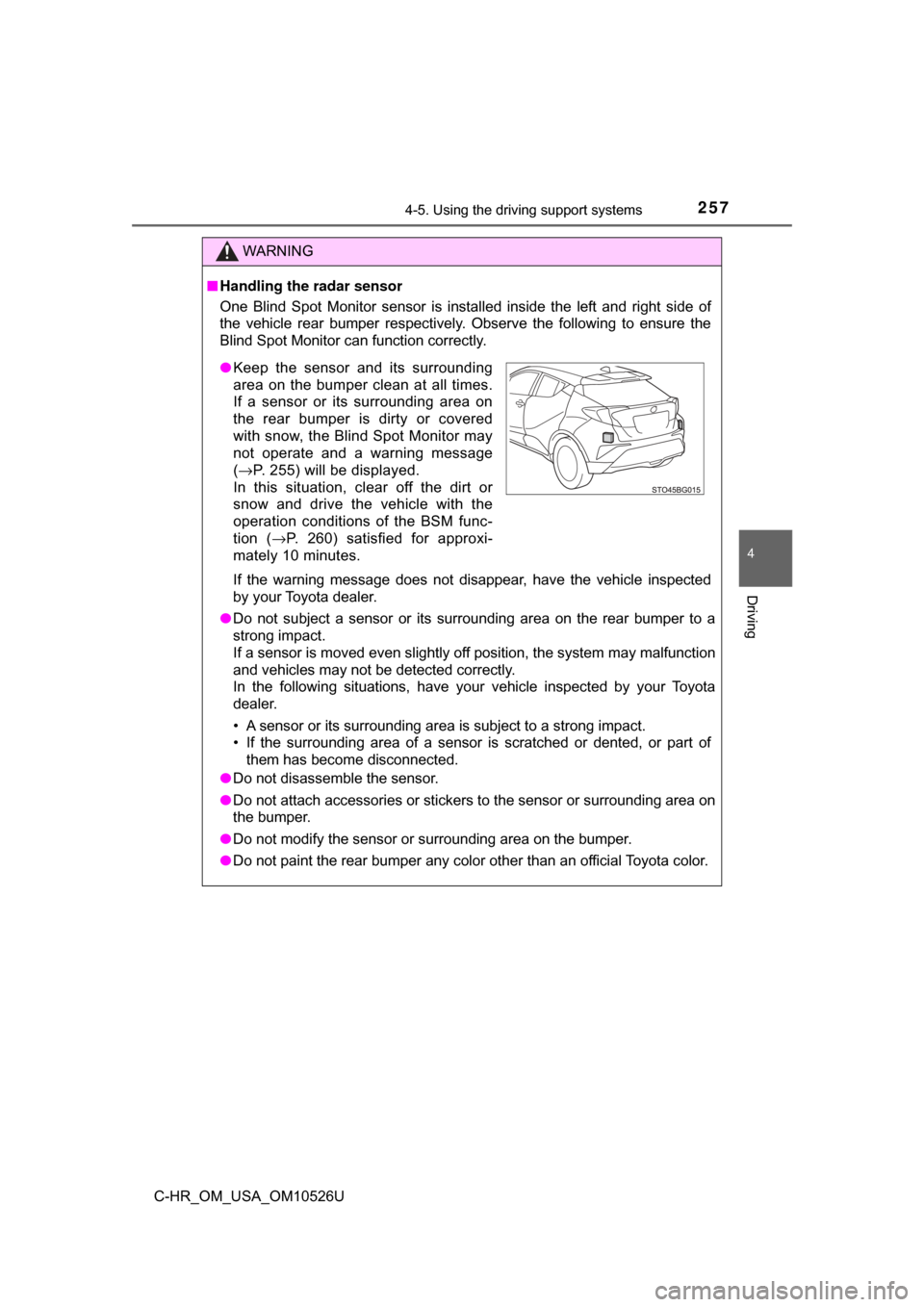
One Blind Spot Monitor sensor is installed inside the left and right side of
the vehicle rear bumper respectively. Observe the following to ensure the
Blind Spot Monitor can function correctly.
If the warning message does not disappear, have the vehicle inspected
by your Toyota dealer.
● Do not subject a sensor or its surrounding area on the rear bumper to a
strong impact.
If a sensor is moved even slightly off position, the system may malfunction
and vehicles may not be detected correctly.
In the following situations, have your vehicle inspected by your Toyota
dealer.
• A sensor or its surrounding area is subject to a strong impact.
• If the surrounding area of a sensor is scratched or dented, or part of
them has become disconnected.
● Do not disassemble the sensor.
● Do not attach accessories or stickers to the sensor or surrounding area on
the bumper.
● Do not modify the sensor or surrounding area on the bumper.
● Do not paint the rear bumper any color other than an official Toyota color.
●Keep the sensor and its surrounding
area on the bumper clean at all times.
If a sensor or its surrounding area on
the rear bumper is dirty or covered
with snow, the Blind Spot Monitor may
not operate and a warning message
(→ P. 255) will be displayed.
In this situation, clear off the dirt or
snow and drive the vehicle with the
operation conditions of the BSM func-
tion ( →P. 260) satisfied for approxi-
mately 10 minutes.
Page 258 of 516
2584-5. Using the driving support systems
C-HR_OM_USA_OM10526U
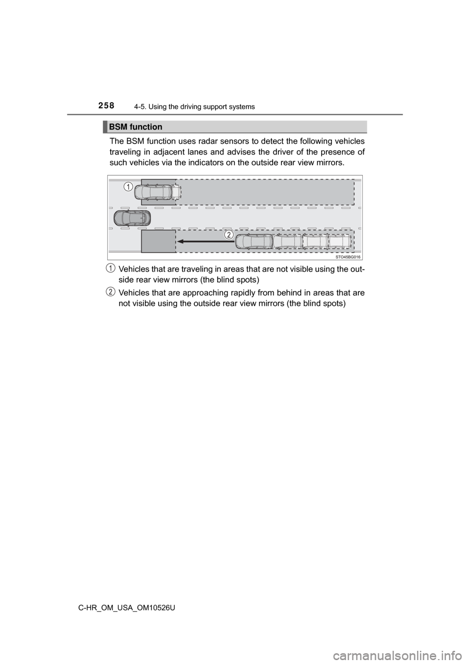
The BSM function uses radar sensor s to detect the following vehicles
traveling in adjacent lanes and advise s the driver of the presence of
such vehicles via the indicators on the outside rear view mirrors.
Vehicles that are traveling in areas that are not visible using the out-
side rear view mirrors (the blind spots)
Vehicles that are approaching rapi dly from behind in areas that are
not visible using the outside rear view mirrors (the blind spots)
BSM function
Page 259 of 516
2594-5. Using the driving support systems
4
Driving
C-HR_OM_USA_OM10526U
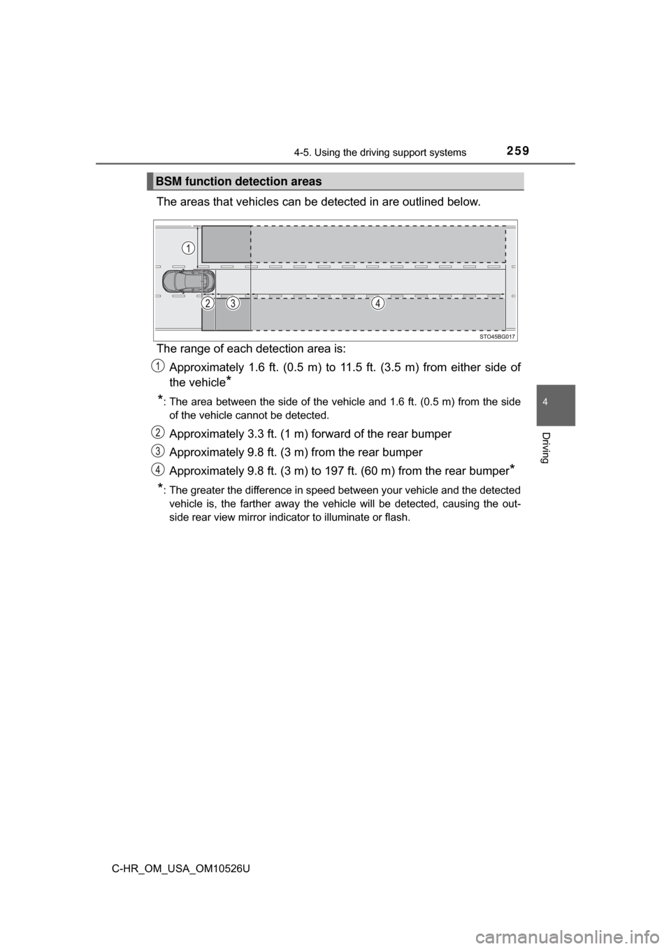
The areas that vehicles can be detected in are outlined below.
The range of each detection area is: Approximately 1.6 ft. (0.5 m) to 11.5 ft. (3.5 m) from either side of
the vehicle
*
*
: The area between the side of the vehicle and 1.6 ft. (0.5 m) from the side of the vehicle cannot be detected.
Approximately 3.3 ft. (1 m) forward of the rear bumper
Approximately 9.8 ft. (3 m) from the rear bumper
Approximately 9.8 ft. (3 m) to 197 ft. (60 m) from the rear bumper
*
*
: The greater the difference in speed between your vehicle and the detected vehicle is, the farther away the vehicle will be detected, causing the out-
side rear view mirror indicator to illuminate or flash.
BSM function detection areas
Page 260 of 516
2604-5. Using the driving support systems
C-HR_OM_USA_OM10526U
■The BSM function is operational when
The BSM function is operational when all of the following conditions are met:
●The BSM system is set to on (→P. 255)
● The shift lever is in a position other than R.
● Vehicle speed is greater than approximately 10 mph (16 km/h)
■ The BSM function will detect a vehicle when
The BSM function will detect a vehicle present in the detection area in the
following situations:
●A vehicle in an adjacent lane overtakes your vehicle.
● Another vehicle enters the detection area when it changes lanes.
■ Conditions under which the BSM function will not detect a vehicle
The BSM function is not designed to detect the following types of vehicles
and/or objects:
●Small motorcycles, bicycles, pedestrians, etc.
*
●Vehicles traveling in the opposite direction
● Guardrails, walls, signs, parked vehi cles and similar stationary objects
*
●Following vehicles that are in the same lane*
●Vehicles traveling 2 lanes away from your vehicle*
*
: Depending on conditions, detection of a vehicle and/or object may occur.
WARNING
■ Cautions regarding the use of the system
The driver is solely responsible for safe driving. Always drive safely, taking
care to observe your surroundings.
The Blind Spot Monitor function is a supplementary function which alerts the
driver that a vehicle is present in the blind spot. Do not overly rely on the
Blind Spot Monitor function. The function cannot judge if it is safe to change
lanes, therefore over reliance could cause an accident resulting in death or
serious injury.
According to conditions, the system may not function correctly. Therefore
the driver’s own visual confirmation of safety is necessary.