display TOYOTA C-HR 2018 1.G Owners Manual
[x] Cancel search | Manufacturer: TOYOTA, Model Year: 2018, Model line: C-HR, Model: TOYOTA C-HR 2018 1.GPages: 516, PDF Size: 9.32 MB
Page 2 of 516
TABLE OF CONTENTS2
C-HR_OM_USA_OM10526UFor your information....................... 6
Reading this manual .................... 10
How to search .............................. 11
Pictorial index .............................. 12
1-1. For safe use
Before driving ...................... 22
For safety drive ................... 24
Seat belts ............................ 26
SRS airbags ........................ 32
Front passenger occupant classification system ......... 46
Exhaust gas precautions ..... 53
1-2. Child safety Riding with children ............. 54
Child restraint systems ........ 55
1-3. Theft deterrent system Engine immobilizer system............................... 74
Theft prevention labels (U.S.A.) ............................. 76
2. Instrument cluster Warning lights and indicators........................... 78
Gauges and meters............. 86
Multi-information display ..... 89 3-1. Key information
Keys..................................... 98
3-2. Opening, closing and locking the doors
Side doors ......................... 105
Back door .......................... 112
Smart key system .............. 118
3-3. Adjusting the seats Front seats......................... 127
Rear seats ......................... 128
Head restraints .................. 130
3-4. Adjusting the steering wheel and mirrors
Steering wheel ................... 133
Inside rear view mirror ....... 135
Outside rear view mirrors ............................. 137
3-5. Opening and closing the windows
Power windows.................. 140
1For safety and security
2Instrument cluster
3Operation of each
component
Page 5 of 516
5
1
8 7 5 4
3
2
9
C-HR_OM_USA_OM10526U
6
7-1. Essential informationEmergency flashers .......... 396
If your vehicle has to be stopped in
an emergency ................. 397
7-2. Steps to take in an emergency
If your vehicle needs to be towed ..................... 399
If you think something is wrong .............................. 406
Fuel pump shut off system............................. 407
If a warning light turns on or a warning buzzer
sounds ............................ 408
If a warning message is displayed ......................... 418
If you have a flat tire .......... 423
If the engine will not start ................................. 434
If the electronic key does not operate
properly (vehicles with
a smart key system) ........ 436
If the vehicle battery is discharged ...................... 439
If your vehicle overheats ........................ 443
If the vehicle becomes stuck................................ 446 8-1. Specifications
Maintenance data (fuel, oil level, etc.) .......... 450
Fuel information ................. 458
Tire information.................. 461
8-2. Customization Customizable features ....... 474
8-3. Items to initialize Items to initialize ................ 482
Reporting safety defects for U.S. owners ........................ 484
Seat belt instructions for Canadian owners
(in French)................................ 485
SRS airbag instructions for Canadian owners
(in French)................................ 487
What to do if... (Troubleshooting) ..................... 498
Alphabetical index ...................... 502
7When trouble arises8Vehicle specifications
9For owners
Index
Page 15 of 516
15Pictorial index
C-HR_OM_USA_OM10526UMulti-information display . . . . . . . . . . . . . . . . . . . . . . . . . . . . P. 89
If a warning messages or indicator is displayed . . . . . . . . . . . P. 418
Turn signal lever . . . . . . . . . . . . . . . . . . . . . . . . . . . . . . . . . . P. 176
Headlight switch
Headlights/front parking lights/tail lights/
daytime running lights . . . . . . . . . . . . . . . . . . . . . . . . . . . . . . . P. 185
Windshield wiper and washer switch . . . . . . . . . . . . . . . . . P. 195
Rear window wiper and washer switch . . . . . . . . . . . . . . . . P. 198
Usage . . . . . . . . . . . . . . . . . . . . . . . . . . . . . . . . . . . . . . . P. 195, 198
Adding washer fluid . . . . . . . . . . . . . . . . . . . . . . . . . . . . . . . . . P. 352
Emergency flasher switch . . . . . . . . . . . . . . . . . . . . . . . . . . P. 396
Hood lock release lever. . . . . . . . . . . . . . . . . . . . . . . . . . . . . P. 338
Tilt and telescopic steering lock release lever . . . . . . . . . . P. 133
Air conditioning system . . . . . . . . . . . . . . . . . . . . . . . . . . . . P. 290
Usage . . . . . . . . . . . . . . . . . . . . . . . . . . . . . . . . . . . . . . . . . . . P. 290
Rear window defogger . . . . . . . . . . . . . . . . . . . . . . . . . . . . . . . P. 293
Seat heaters
*3. . . . . . . . . . . . . . . . . . . . . . . . . . . . . . . . . . . . . P. 298
*1: Vehicles without a smart key system
*2: Vehicles with a smart key system
*3: If equipped
Page 67 of 516
671-2. Child safety
1
For safety and security
C-HR_OM_USA_OM10526U■
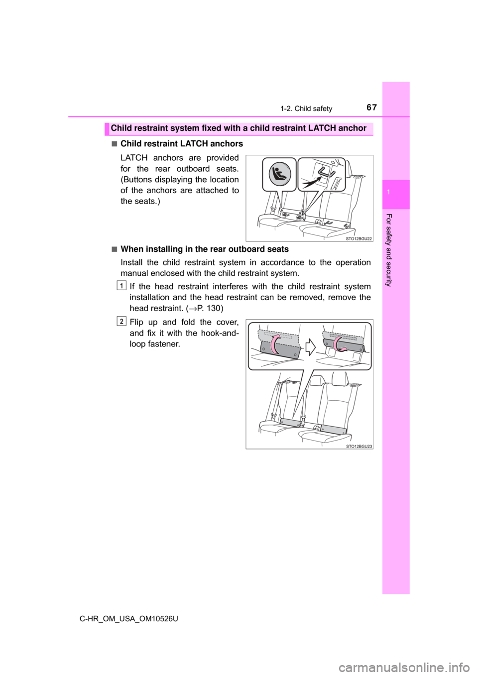
Child restraint LATCH anchors
LATCH anchors are provided
for the rear outboard seats.
(Buttons displaying the location
of the anchors are attached to
the seats.)
■When installing in the rear outboard seats
Install the child restraint system in accordance to the operation
manual enclosed with the child restraint system.
If the head restraint interferes with the child restraint system
installation and the head restraint can be removed, remove the
head restraint. ( →P. 130)
Flip up and fold the cover,
and fix it with the hook-and-
loop fastener.
Child restraint system fixed with a child restraint LATCH anchor
1
2
Page 77 of 516

77
Instrument cluster2
C-HR_OM_USA_OM10526U2. Instrument cluster
Warning lights and indicators .......................... 78
Gauges and meters ............ 86
Multi-information display ..... 89
Page 82 of 516
822. Instrument cluster
C-HR_OM_USA_OM10526U
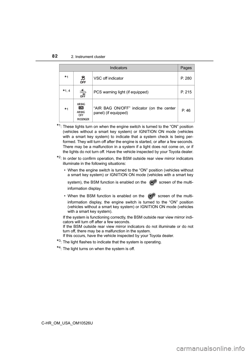
*1: These lights turn on when the engine switch is turned to the “ON” position(vehicles without a smart key system) or IGNITION ON mode (vehicles
with a smart key system) to indicate that a system check is being per-
formed. They will turn off after the engine is started, or after a few seconds.
There may be a malfunction in a system if a light does not come on, or if
the lights do not turn off. Have the vehicle inspected by your Toyota dealer.
*2: In order to confirm operation, the BS M outside rear view mirror indicators
illuminate in the following situations:
• When the engine switch is turned to the “ON” position (vehicles without a smart key system) or IGNITION ON mode (vehicles with a smart key
system), the BSM function is enabled on the screen of the multi-
information display.
• When the BSM function is enabled on the screen of the multi- information display, the engine switch is turned to the “ON” position
(vehicles without a smart key system) or IGNITION ON mode (vehicles
with a smart key system).
If the system is functioning correctly, the BSM outside rear view mirror indi-
cators will turn off after a few seconds.
If the BSM outside rear view mirror indicators do not illuminate or do not
turn off, there may be a malfunction in the system.
If this occurs, have the vehicle inspected by your Toyota dealer.
*3: The light flashes to indicate that the system is operating.
*4: The light turns on when the system is off.
*1VSC off indicator P. 280
*1, 4PCS warning light (if equipped) P. 215
*1“AIR BAG ON/OFF” indicator (on the center
panel) (if equipped) P. 4 6
IndicatorsPages
Page 83 of 516
832. Instrument cluster
2
Instrument cluster
C-HR_OM_USA_OM10526U
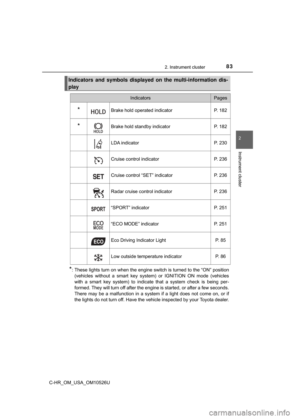
*: These lights turn on when the engine switch is turned to the “ON” position(vehicles without a smart key system) or IGNITION ON mode (vehicles
with a smart key system) to indicate that a system check is being per-
formed. They will turn off after the engine is started, or after a few seconds.
There may be a malfunction in a system if a light does not come on, or if
the lights do not turn off. Have the vehicle inspected by your Toyota dealer.
Indicators and symbols displaye d on the multi-information dis-
play
IndicatorsPages
*Brake hold operated indicator P. 182
*Brake hold standby indicatorP. 182
LDA indicator P. 230
Cruise control indicator P. 236
Cruise control “SET” indicator P. 236
Radar cruise control indicator P. 236
“SPORT” indicator P. 251
“ECO MODE” indicator P. 251
Eco Driving Indicator Light P. 85
Low outside temperature indicator P. 86
Page 84 of 516
842. Instrument cluster
C-HR_OM_USA_OM10526U
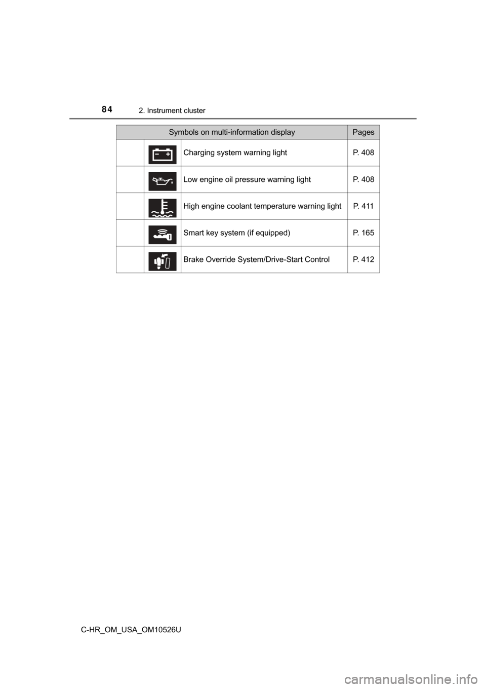
Symbols on multi-information displayPages
Charging system warning light P. 408
Low engine oil pressure warning light P. 408
High engine coolant temperature warning light P. 411
Smart key system (if equipped) P. 165
Brake Override System/Drive-Start Control P. 412
Page 86 of 516
862. Instrument cluster
C-HR_OM_USA_OM10526U
Gauges and meters
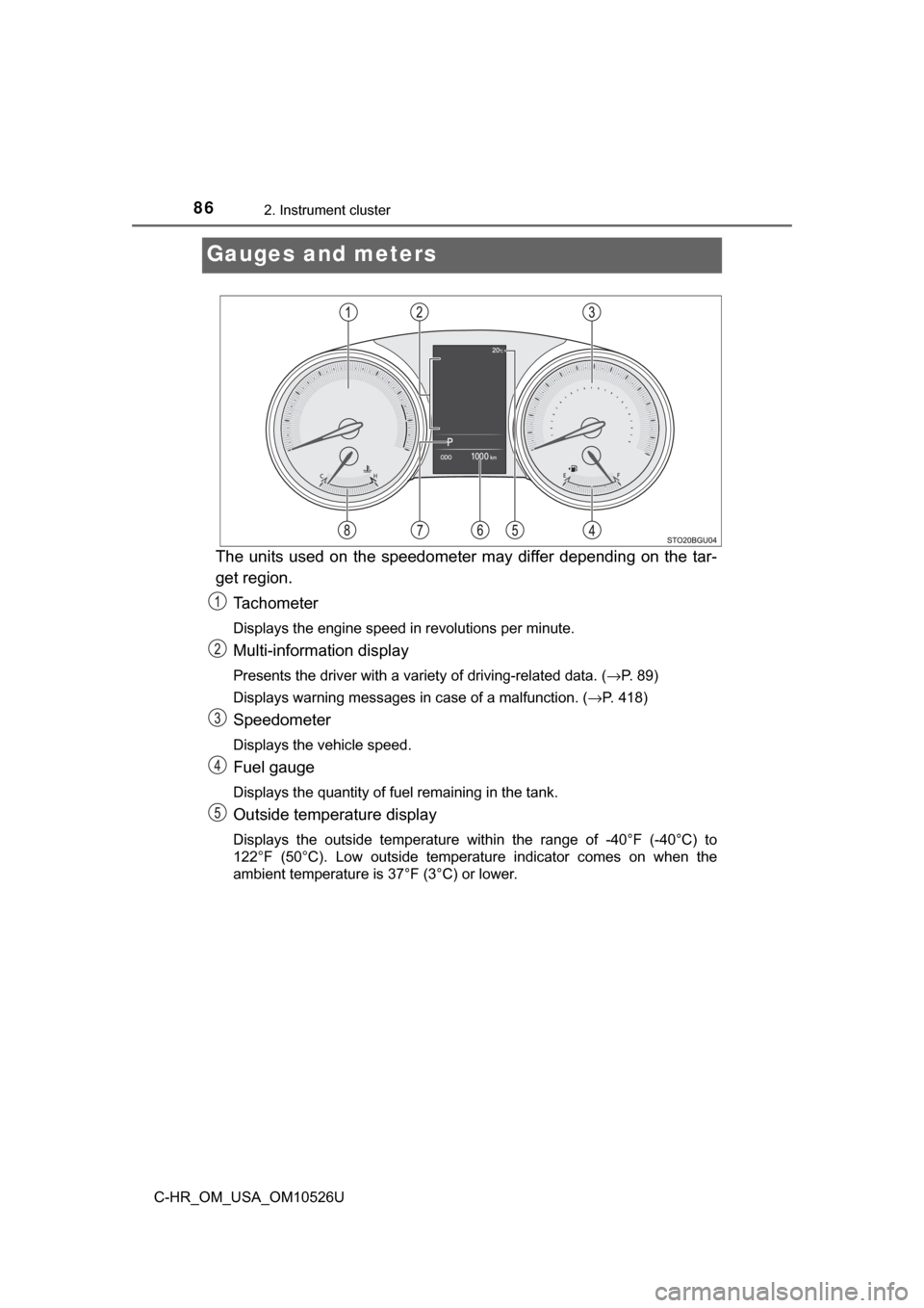
The units used on the speedometer may differ depending on the tar-
get region.Tachometer
Displays the engine speed in revolutions per minute.
Multi-information display
Presents the driver with a variety of driving-related data. ( →P. 89)
Displays warning messages in case of a malfunction. ( →P. 418)
Speedometer
Displays the vehicle speed.
Fuel gauge
Displays the quantity of fuel remaining in the tank.
Outside temperature display
Displays the outside temperature within the range of -40°F (-40°C) to
122°F (50°C). Low outside temperature indicator comes on when the
ambient temperature is 37°F (3°C) or lower.
Page 87 of 516
872. Instrument cluster
2
Instrument cluster
C-HR_OM_USA_OM10526U
Odometer and trip meter display
Displays the following items.
Odometer:
Displays the total distance the vehicle has been driven.
Trip meter:
Displays the distance the vehicle has been driven since the meter was last
reset. Trip meters A and B can be used to record and display different dis-
tances independently.
Maintenance required information (U.S.A. only):
Displays the remaining distance until the engine oil should be changed. If
“-” is displayed before distance, it means oil maintenance is overdue. Have
the engine oil changed by your Toyota dealer.• Displays the maintenance required information when the engine switch is turned to the “ON” position (vehicles without smart key system) or in
IGNITION ON mode (vehicles with smart key system).
• Maintenance required information reset method (→P. 328)
Shift position and shift range display
Displays the selected shift position or selected shift range. ( →P. 171)
Engine coolant temperature gauge
Displays the engine coolant temperature.
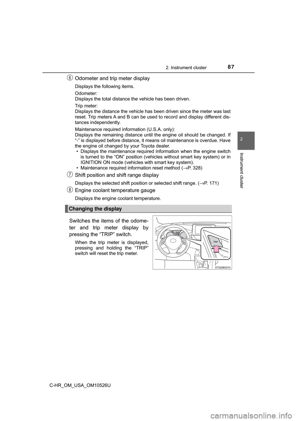
Switches the items of the odome-
ter and trip meter display by
pressing the “TRIP” switch.
When the trip meter is displayed,
pressing and holding the “TRIP”
switch will reset the trip meter.
Changing the display