display TOYOTA C-HR 2018 1.G Repair Manual
[x] Cancel search | Manufacturer: TOYOTA, Model Year: 2018, Model line: C-HR, Model: TOYOTA C-HR 2018 1.GPages: 516, PDF Size: 9.32 MB
Page 268 of 516
2684-5. Using the driving support systems
C-HR_OM_USA_OM10526U
Rear view monitor system
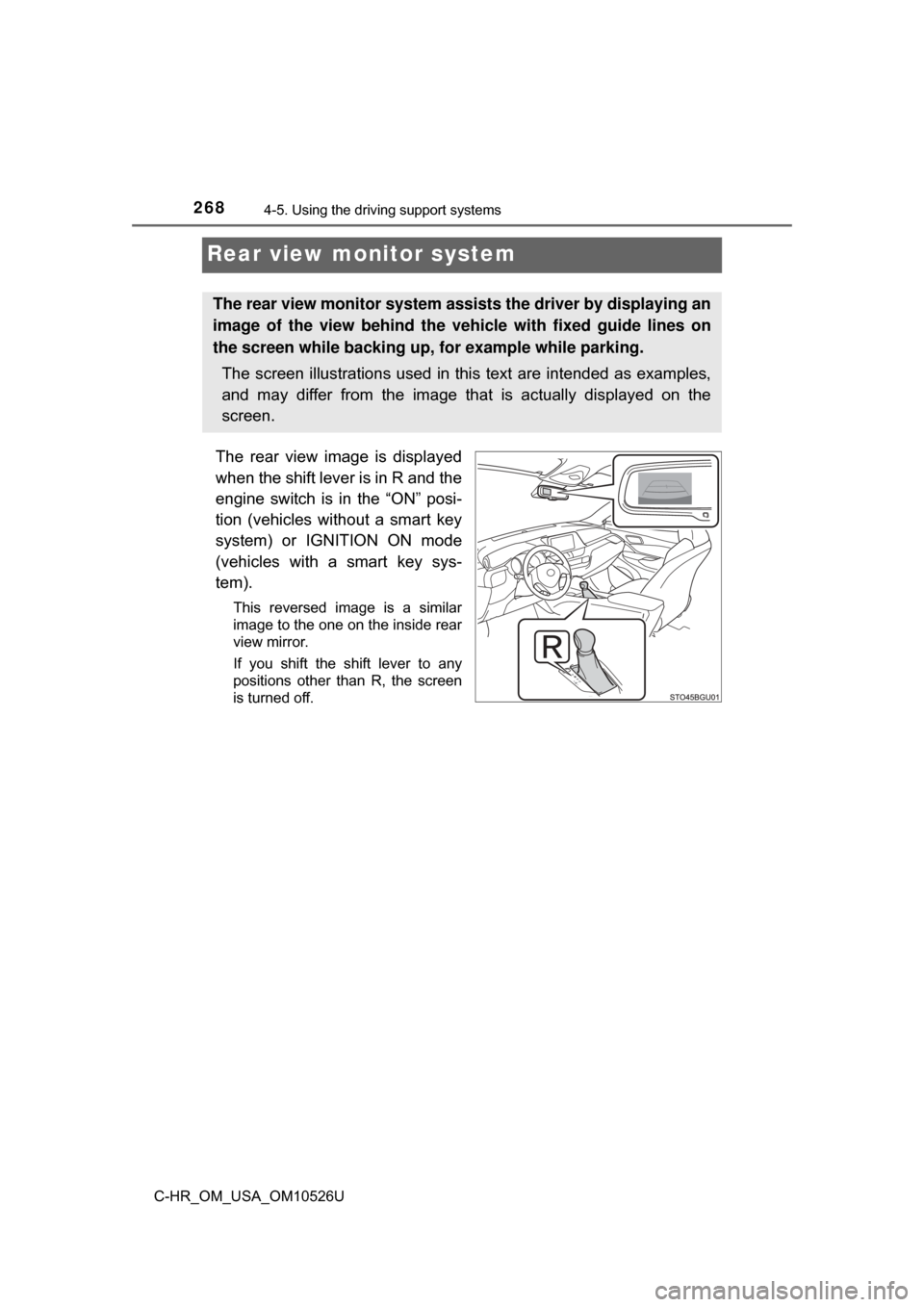
The rear view image is displayed
when the shift lever is in R and the
engine switch is in the “ON” posi-
tion (vehicles without a smart key
system) or IGNITION ON mode
(vehicles with a smart key sys-
tem).
This reversed image is a similar
image to the one on the inside rear
view mirror.
If you shift the shift lever to any
positions other than R, the screen
is turned off.
The rear view monitor system assists the driver by displaying an
image of the view behind the veh icle with fixed guide lines on
the screen while backing up, for example while parking.
The screen illustrations used in this text are intended as examples,
and may differ from the image that is actually displayed on the
screen.
Page 269 of 516

2694-5. Using the driving support systems
4
Driving
C-HR_OM_USA_OM10526U■
When using the rear view monitor system
The anti-glare function of the in
side rear view mirror will be can-
celed.
■Display mode
The rear view monitor display mode can be adjusted when the
engine switch is in the “ON” position (vehicles without a smart key
system) or IGNITION ON mode (veh icles with a smart key system)
and the shift lever is in R.
To select a display language (English, French or Spanish).
Push and hold the “AUTO” button for 6 seconds, then release.
Push the “AUTO” button.
Each time the “AUTO” button is pushed and released, the lan-
guage will change.
The warning message should flash 5 seconds after the button is
released, indicating that the change has been completed.
1
2
3
Page 270 of 516
2704-5. Using the driving support systems
C-HR_OM_USA_OM10526U■
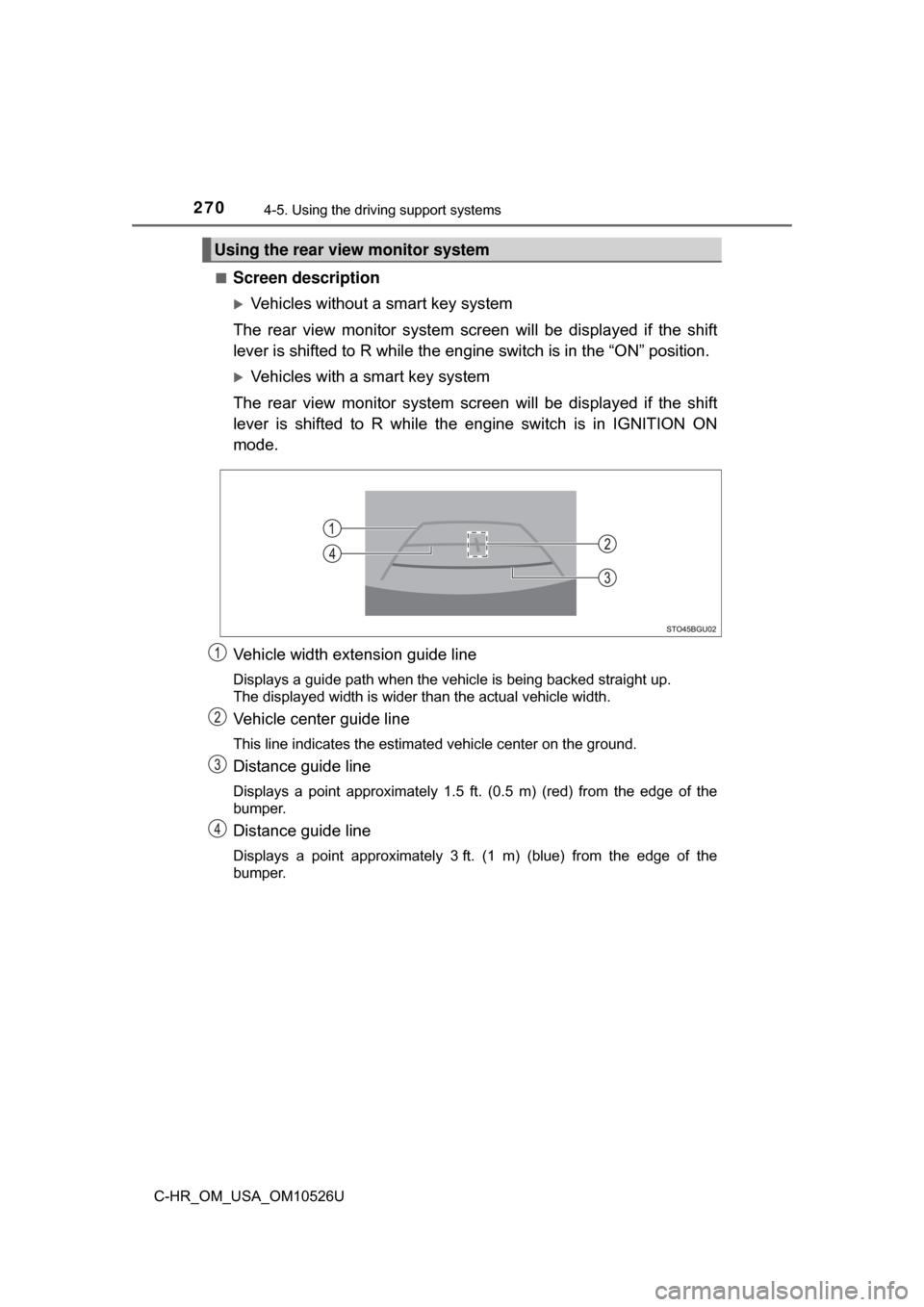
Screen description
Vehicles without a smart key system
The rear view monitor system scr een will be displayed if the shift
lever is shifted to R while the engin e switch is in the “ON” position.
Vehicles with a smart key system
The rear view monitor system scr een will be displayed if the shift
lever is shifted to R while the engine switch is in IGNITION ON
mode.
Vehicle width extension guide line
Displays a guide path when the vehicle is being backed straight up.
The displayed width is wider than the actual vehicle width.
Vehicle center guide line
This line indicates the estimated vehicle center on the ground.
Distance guide line
Displays a point approximately 1.5 ft. (0.5 m) (red) from the edge of the
bumper.
Distance guide line
Displays a point approximately 3 ft. (1 m) (blue) from the edge of the
bumper.
Using the rear view monitor system
Page 271 of 516
2714-5. Using the driving support systems
4
Driving
C-HR_OM_USA_OM10526U■
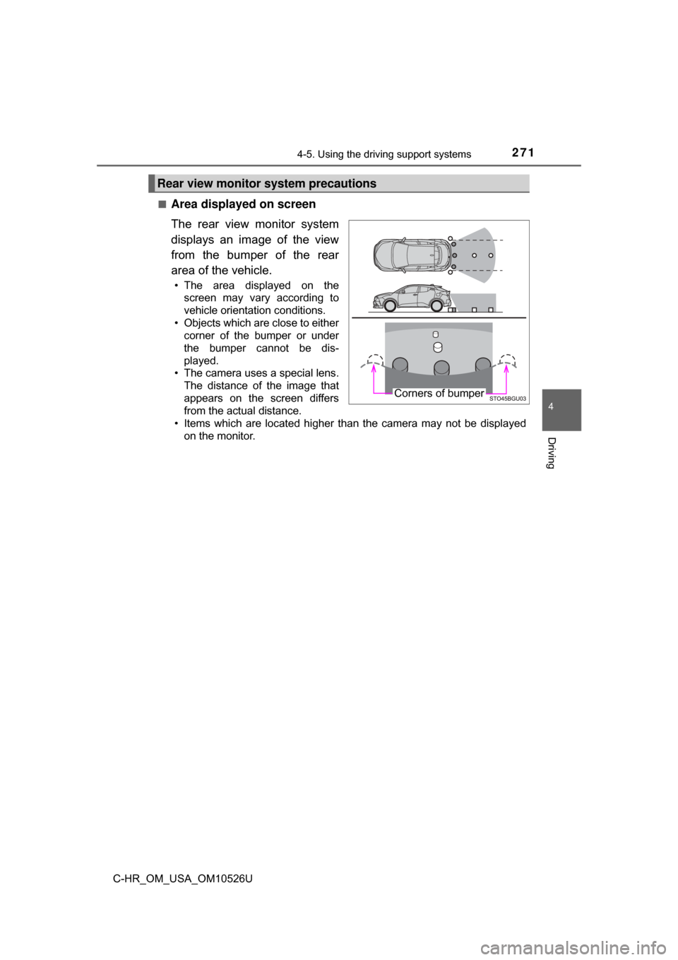
Area displayed on screen
The rear view monitor system
displays an image of the view
from the bumper of the rear
area of the vehicle.
• The area displayed on the
screen may vary according to
vehicle orientation conditions.
• Objects which are close to either corner of the bumper or under
the bumper cannot be dis-
played.
• The camera uses a special lens.
The distance of the image that
appears on the screen differs
from the actual distance.
• Items which are located higher than the camera may not be displayed on the monitor.
Rear view monitor system precautions
Corners of bumper
Page 274 of 516
2744-5. Using the driving support systems
C-HR_OM_USA_OM10526U
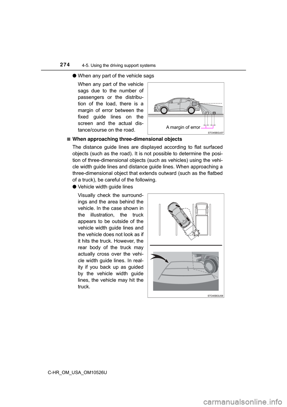
●When any part of the vehicle sags
When any part of the vehicle
sags due to the number of
passengers or the distribu-
tion of the load, there is a
margin of error between the
fixed guide lines on the
screen and the actual dis-
tance/course on the road.
■When approaching thre e-dimensional objects
The distance guide lines are displayed according to flat surfaced
objects (such as the road). It is not possible to determine the posi-
tion of three-dimensional objects (s uch as vehicles) using the vehi-
cle width guide lines and distance guide lines. When approaching a
three-dimensional object that extends outward (such as the flatbed
of a truck), be careful of the following.
● Vehicle width guide lines
Visually check the surround-
ings and the area behind the
vehicle. In the case shown in
the illustration , the truck
appears to be outside of the
vehicle width guide lines and
the vehicle does not look as if
it hits the truck. However, the
rear body of the truck may
actually cross over the vehi-
cle width guide lines. In real-
ity if you back up as guided
by the vehicle width guide
lines, the vehicle may hit the
truck.
A margin of error
Page 277 of 516
2774-5. Using the driving support systems
4
Driving
C-HR_OM_USA_OM10526U
WARNING
■When using the rear view monitor system
The rear view monitor system is a supplemental device intended to assist
the driver when backing up. When backing up, be sure to check visually
behind and all around the vehicle before proceeding.
Observe the following precautions to avoid an accident that could result in
death or serious injuries.
● Never depend on the rear view monitor system entirely when backing up.
The image and the position of the guide lines displayed on the screen may
differ from the actual state.
Use caution, just as you would when backing up any vehicle.
● Be sure to back up slowly, depressing the brake pedal to control vehicle
speed.
● The instructions given are only guide lines.
When and how much to turn the steering wheel will vary according to traf-
fic conditions, road surface conditions, vehicle condition, etc. when park-
ing. It is necessary to be fully aware of this before using the rear view
monitor system.
● When parking, be sure to check that the parking space will accommodate
your vehicle before maneuvering into it.
● Do not use the rear view monitor system in the following cases:
• On icy or slick road surfaces, or in snow
• When using tire chains or the compact spare tire
• When the back door is not closed completely
• On roads that are not flat or straight, such as curves or slopes
● In low temperatures, the screen may darken or the image may become
faint. The image could distort when the vehicle is moving, or you may
become unable to see the image on the screen. Be sure to check visually
behind and all around the vehicle before proceeding.
● If the tire sizes are changed, the position of the fixed guide lines displayed
on the screen may change.
● The camera uses a special lens. The distances between objects and
pedestrians that appear in the image displayed on the screen will differ
from the actual distances. ( →P. 272)
Page 280 of 516
2804-5. Using the driving support systems
C-HR_OM_USA_OM10526U
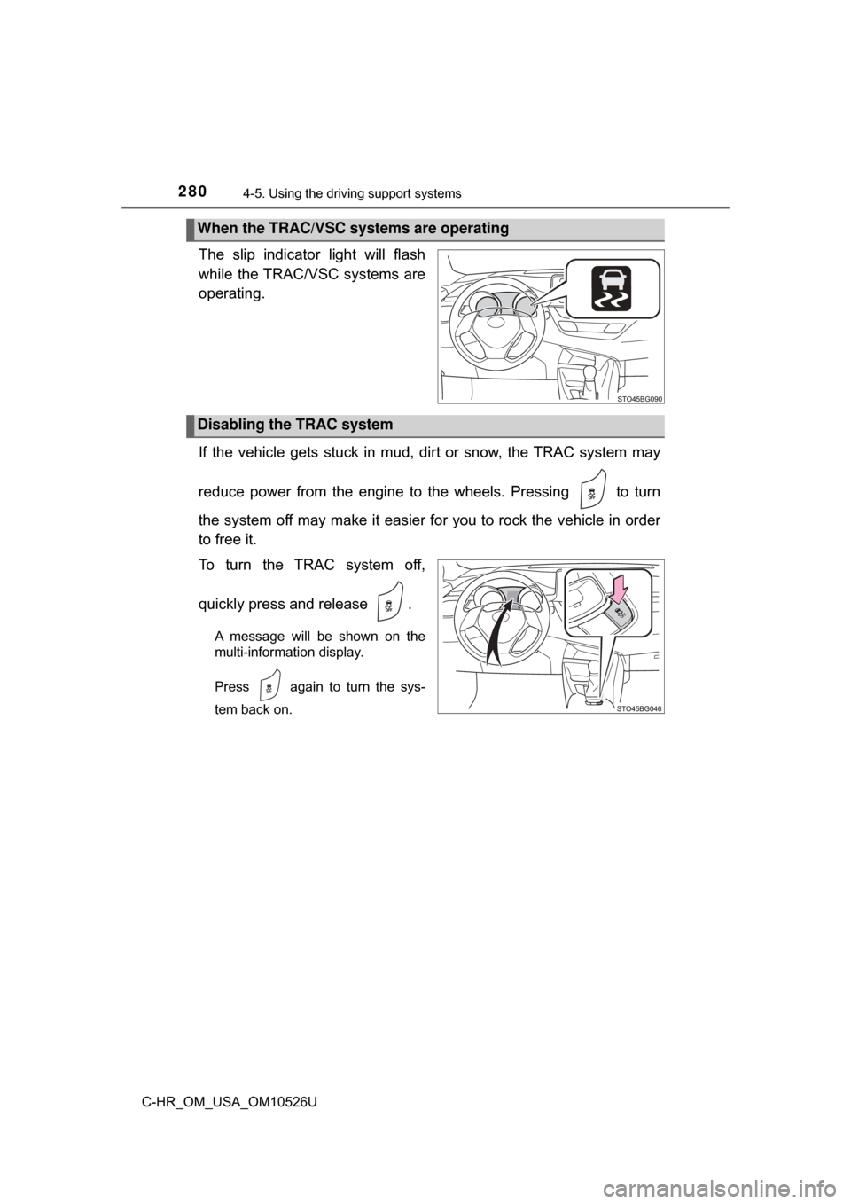
The slip indicator light will flash
while the TRAC/VSC systems are
operating.
If the vehicle gets stuck in mud, di rt or snow, the TRAC system may
reduce power from the engine to the wheels. Pressing to turn
the system off may make it easier for you to rock the vehicle in order
to free it.
To turn the TRAC system off,
quickly press and release .
A message will be shown on the
multi-information display.
Press again to turn the sys-
tem back on.
When the TRAC/VSC systems are operating
Disabling the TRAC system
Page 281 of 516
2814-5. Using the driving support systems
4
Driving
C-HR_OM_USA_OM10526U
■Turning off both TRAC and VSC systems
To turn the TRAC and VSC systems off, press and hold for more than 3
seconds while the vehicle is stopped.
The VSC off indicator light will come on and the message will be shown on
the multi-information display.
*
*
: On vehicles with pre-collision system, pre-collision brake assist and pre-
collision braking will also be disabled. The PCS warning light will come on
and the message will be shown on the multi-information display. ( →P. 410)
Press again to turn the systems back on.
■ When the message is displayed on th e multi-information display show-
ing that TRAC has been disable d even if has not been pressed
TRAC cannot be operated. Contact your Toyota dealer.
■ Sounds and vibrations caused by the ABS, brake assist, VSC, TRAC and
hill-start assist control systems
●A sound may be heard from the engine compartment when the brake pedal
is depressed repeatedly, when the engine is started or just after the vehicle
begins to move. This sound does not indicate that a malfunction has
occurred in any of these systems.
● Any of the following conditions may occur when the above systems are
operating. None of these indicates that a malfunction has occurred.
• Vibrations may be felt through the vehicle body and steering.
• A motor sound may be heard also after the vehicle comes to a stop.
• The brake pedal may pulsate slightly after the ABS is activated.
• The brake pedal may move down slightly after the ABS is activated.
Page 314 of 516
3145-4. Using the other interior features
C-HR_OM_USA_OM10526U
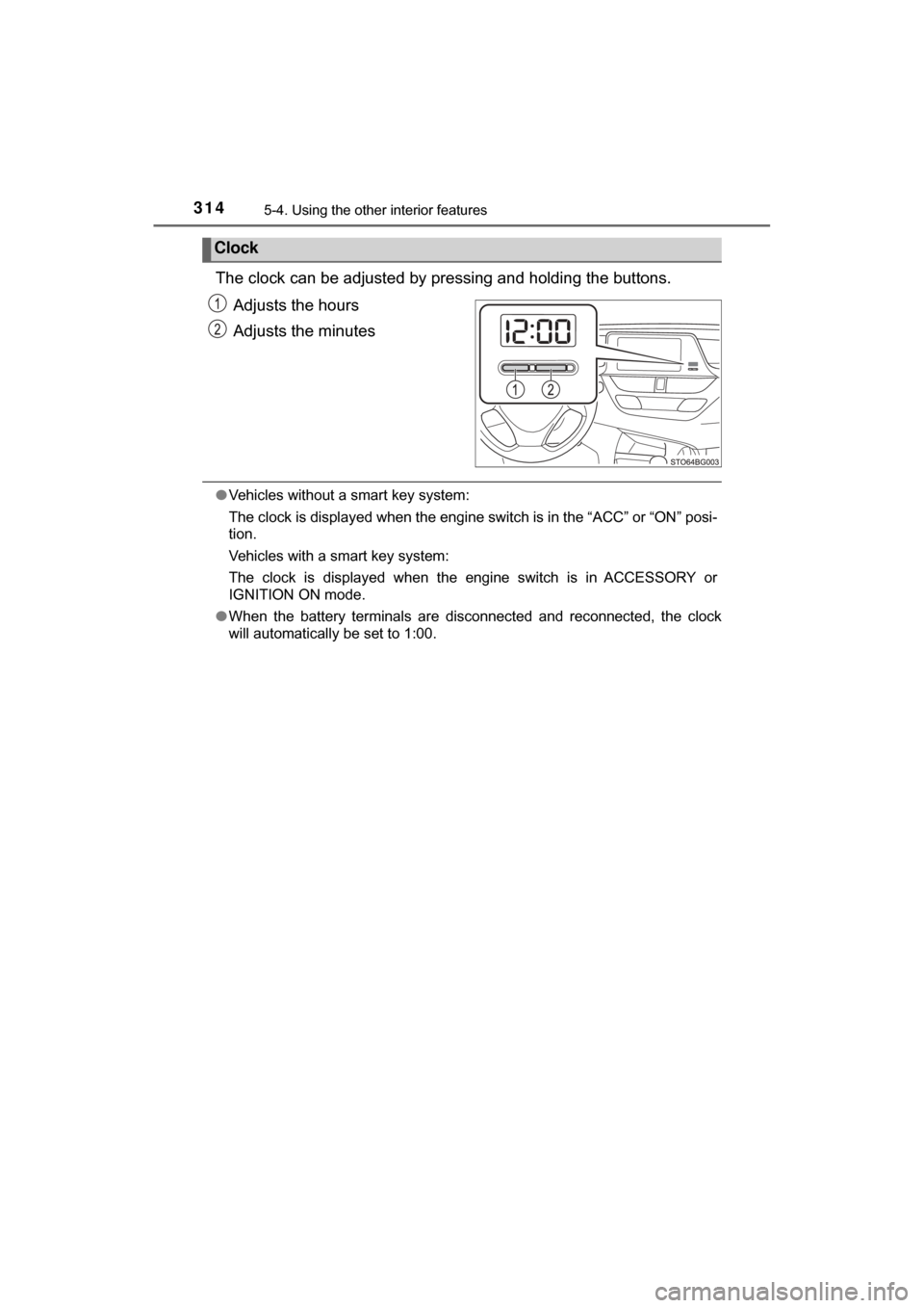
The clock can be adjusted by pressing and holding the buttons.
Adjusts the hours
Adjusts the minutes
●Vehicles without a smart key system:
The clock is displayed when the engine switch is in the “ACC” or “ON” posi-
tion.
Vehicles with a smart key system:
The clock is displayed when the engine switch is in ACCESSORY or
IGNITION ON mode.
● When the battery terminals are disconnected and reconnected, the clock
will automatically be set to 1:00.
Clock
Page 328 of 516

3286-2. Maintenance
C-HR_OM_USA_OM10526U
■Repair and replacement
It is recommended that genuine Toyota parts be used for repairs to ensure
performance of each system. If non-Toyota parts are used in replacement or if
a repair shop other than a Toyota dealer performs repairs, confirm the war-
ranty coverage.
■ Resetting the message indicating maintenance is required (U.S.A. only)
After the required maintenance is performed according to the maintenance
schedule, please reset the message.
To reset the message, follow the procedure described below:
Switch the display to the trip meter “A” when the engine is running. ( →P. 87)
Turn the engine switch off.
Vehicles without a smart key system:
While pressing the “TRIP” switch ( →P. 87), turn the engine switch to the
“ON” position (do not start the engine because the reset mode wil\
l be can-
celed). Continue to press and hold the switch until the trip meter displays
“00000”.
Vehicles with a smart key system:
While pressing the “TRIP” switch ( →P. 87), turn the engine switch to the
IGNITION ON mode (do not start the engine because the reset mode will
be canceled). Continue to press and hold the switch until the trip meter dis-
plays “00000”.
■ Allow inspection and repairs to be performed by a Toyota dealer
●Toyota technicians are well-trained specialists and are kept up to date with
the latest service information. They are well informed about the operations
of all systems on your vehicle.
● Keep a copy of the repair order. It proves that the maintenance that has
been performed is under warranty cove rage. If any problem should arise
while your vehicle is under warranty, your Toyota dealer will promptly take
care of it.
1
2
3