TOYOTA CAMRY 1999 Service Repair Manual
Manufacturer: TOYOTA, Model Year: 1999, Model line: CAMRY, Model: TOYOTA CAMRY 1999Pages: 4592, PDF Size: 55.16 MB
Page 2271 of 4592
A09404
9
W±L
IJ2
E6 10
IG3
E6 18
LOCK IN
E1 16
EC
BRJ20
IJ210
BR 1
2A/C Compressor
Lock SensorECM
BR W±L
W±L
B
B BRJ/C
AA
A
BR
IG3 J7
6J/C
BR
± DIAGNOSTICSENGINE
DI±119
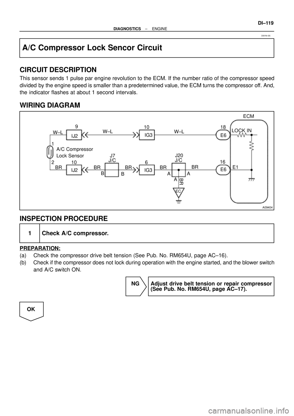
A/C Compressor Lock Sencor Circuit
CIRCUIT DESCRIPTION
This sensor sends 1 pulse par engine revolution to the ECM. If the number ratio of the compressor speed
divided by the engine speed is smaller than a predetermined value, the ECM turns the compressor off. And,
the indicator flashes at about 1 second intervals.
WIRING DIAGRAM
INSPECTION PROCEDURE
1 Check A/C compressor.
PREPARATION:
(a) Check the compressor drive belt tension (See Pub. No. RM654U, page AC±16).
(b) Check if the compressor does not lock during operation with the engine started, and the blower switch
and A/C switch ON.
NG Adjust drive belt tension or repair compressor
(See Pub. No. RM654U, page AC±17).
OK
DI01N±05
Page 2272 of 4592
N15622
12
N02774
LOCK IN Signal Waveform
20 msec./Division (Idling) 0 V
0.2 V/Div.
DI±120
± DIAGNOSTICSENGINE
2 Check A/C compressor lock sensor.
PREPARATION:
Disconnect the compressor lock sensor connector.
CHECK:
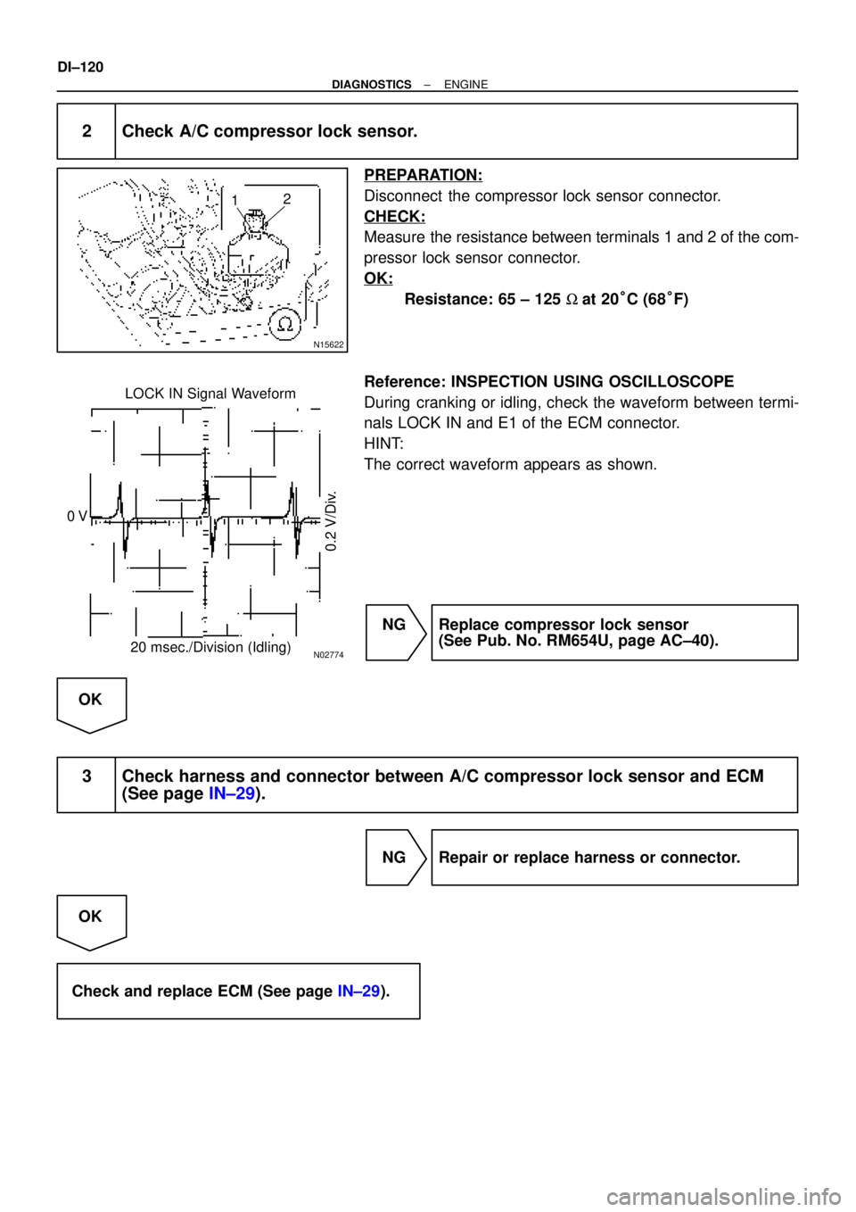
Measure the resistance between terminals 1 and 2 of the com-
pressor lock sensor connector.
OK:
Resistance: 65 ± 125 W at 20°C (68°F)
Reference: INSPECTION USING OSCILLOSCOPE
During cranking or idling, check the waveform between termi-
nals LOCK IN and E1 of the ECM connector.
HINT:
The correct waveform appears as shown.
NG Replace compressor lock sensor
(See Pub. No. RM654U, page AC±40).
OK
3 Check harness and connector between A/C compressor lock sensor and ECM
(See page IN±29).
NG Repair or replace harness or connector.
OK
Check and replace ECM (See page IN±29).
Page 2273 of 4592
A09405
E5
IG2 L±W1
L±R
THR5 V ECM
E2
E59
BR
IG23
BR A/C Evaporator
Temp. Sensor
2 110
A09290BE6653
A09361
ON
E1 THR
(±) (+)
± DIAGNOSTICSENGINE
DI±121
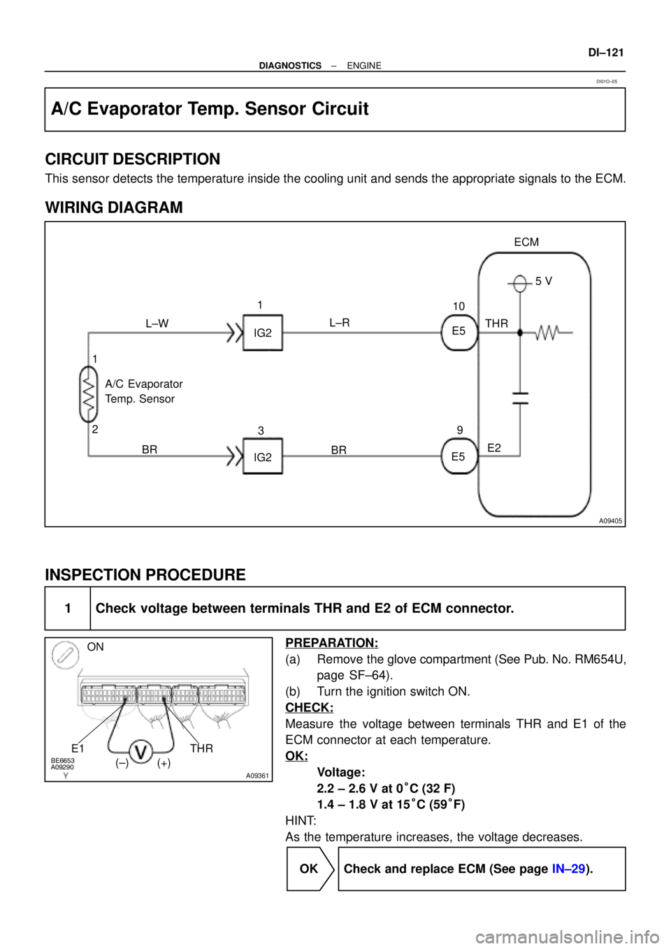
A/C Evaporator Temp. Sensor Circuit
CIRCUIT DESCRIPTION
This sensor detects the temperature inside the cooling unit and sends the appropriate signals to the ECM.
WIRING DIAGRAM
INSPECTION PROCEDURE
1 Check voltage between terminals THR and E2 of ECM connector.
PREPARATION:
(a) Remove the glove compartment (See Pub. No. RM654U,
page SF±64).
(b) Turn the ignition switch ON.
CHECK:
Measure the voltage between terminals THR and E1 of the
ECM connector at each temperature.
OK:
Voltage:
2.2 ± 2.6 V at 0°C (32 F)
1.4 ± 1.8 V at 15°C (59°F)
HINT:
As the temperature increases, the voltage decreases.
OK Check and replace ECM (See page IN±29).
DI01O±05
Page 2274 of 4592
AC0175
Thermometer
Ice
Ohmmeter
Thermistor
More than
10 cm (3.94 in.)
DI±122
± DIAGNOSTICSENGINE
NG
2 Check A/C evaporator temperature sensor.
PREPARATION:
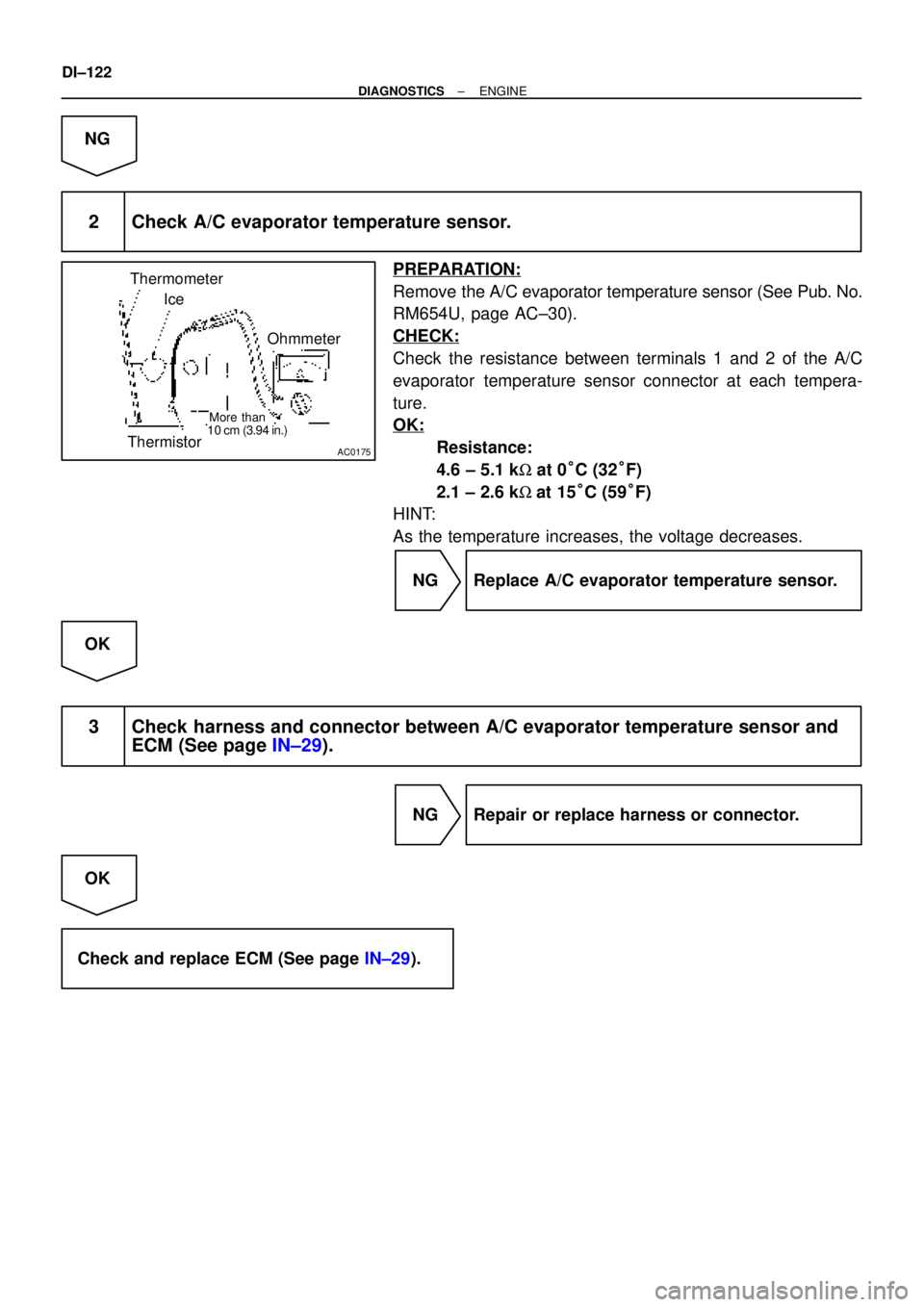
Remove the A/C evaporator temperature sensor (See Pub. No.
RM654U, page AC±30).
CHECK:
Check the resistance between terminals 1 and 2 of the A/C
evaporator temperature sensor connector at each tempera-
ture.
OK:
Resistance:
4.6 ± 5.1 kW at 0°C (32°F)
2.1 ± 2.6 kW at 15°C (59°F)
HINT:
As the temperature increases, the voltage decreases.
NG Replace A/C evaporator temperature sensor.
OK
3 Check harness and connector between A/C evaporator temperature sensor and
ECM (See page IN±29).
NG Repair or replace harness or connector.
OK
Check and replace ECM (See page IN±29).
Page 2275 of 4592
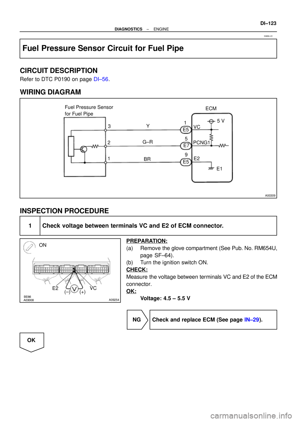
A00309
ECM Fuel Pressure Sensor
for Fuel Pipe
1PCNG1VC
E2 Y
G±RE5
E7
E5 3
25 V
E1 1
5
9
BR
BE6653A03008A09254
ON
E2VC
(±) (+)
± DIAGNOSTICSENGINE
DI±123
Fuel Pressure Sensor Circuit for Fuel Pipe
CIRCUIT DESCRIPTION
Refer to DTC P0190 on page DI±56.
WIRING DIAGRAM
INSPECTION PROCEDURE
1 Check voltage between terminals VC and E2 of ECM connector.
PREPARATION:
(a) Remove the glove compartment (See Pub. No. RM654U,
page SF±64).
(b) Turn the ignition switch ON.
CHECK:
Measure the voltage between terminals VC and E2 of the ECM
connector.
OK:
Voltage: 4.5 ± 5.5 V
NG Check and replace ECM (See page IN±29).
OK
DI650±01
Page 2276 of 4592
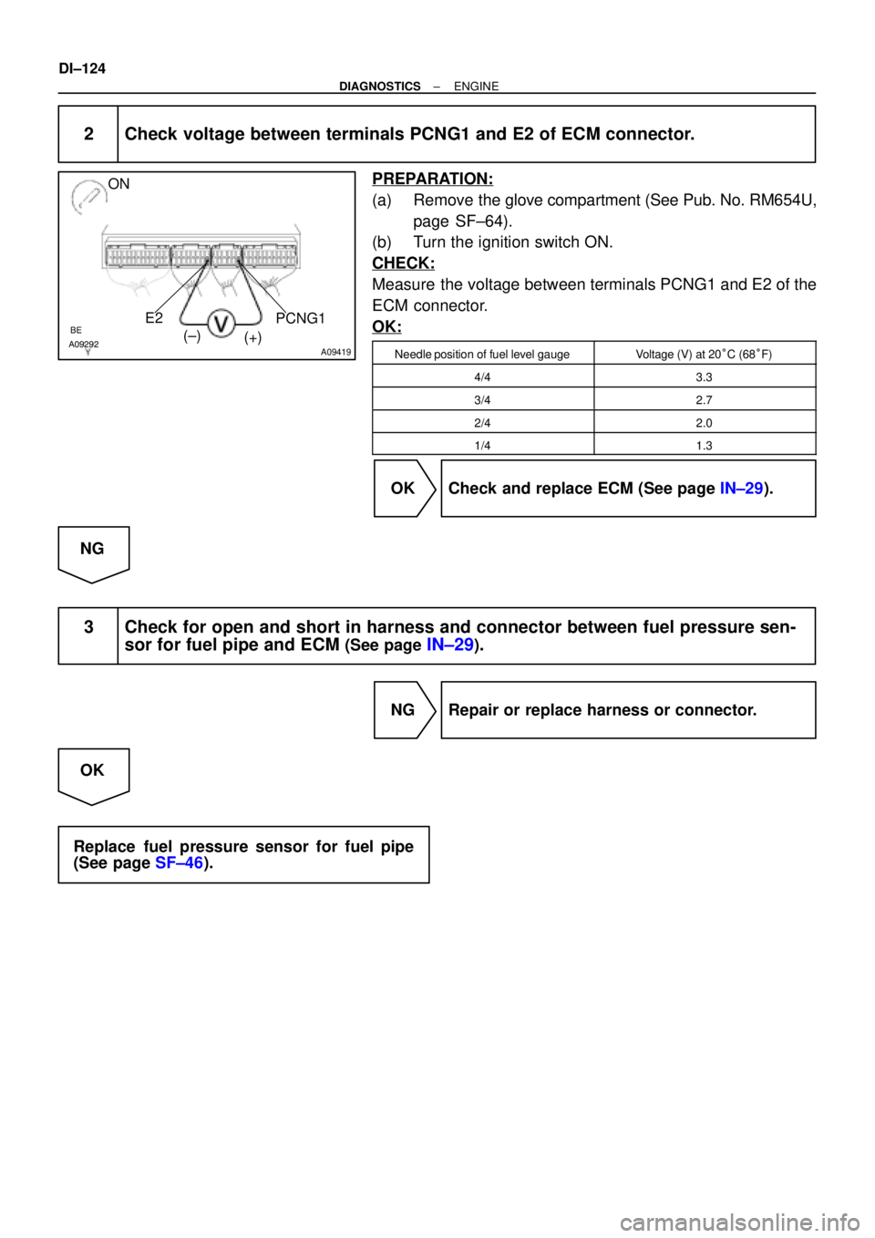
BE6653A09292A09419
E2 ONPCNG1
(±)
(+)
DI±124
± DIAGNOSTICSENGINE
2 Check voltage between terminals PCNG1 and E2 of ECM connector.
PREPARATION:
(a) Remove the glove compartment (See Pub. No. RM654U,
page SF±64).
(b) Turn the ignition switch ON.
CHECK:
Measure the voltage between terminals PCNG1 and E2 of the
ECM connector.
OK:
Needle position of fuel level gaugeVoltage (V) at 20°C (68°F)
4/43.3
3/42.7
2/42.0
1/41.3
OK Check and replace ECM (See page IN±29).
NG
3 Check for open and short in harness and connector between fuel pressure sen-
sor for fuel pipe and ECM
(See page IN±29).
NG Repair or replace harness or connector.
OK
Replace fuel pressure sensor for fuel pipe
(See page SF±46).
Page 2277 of 4592
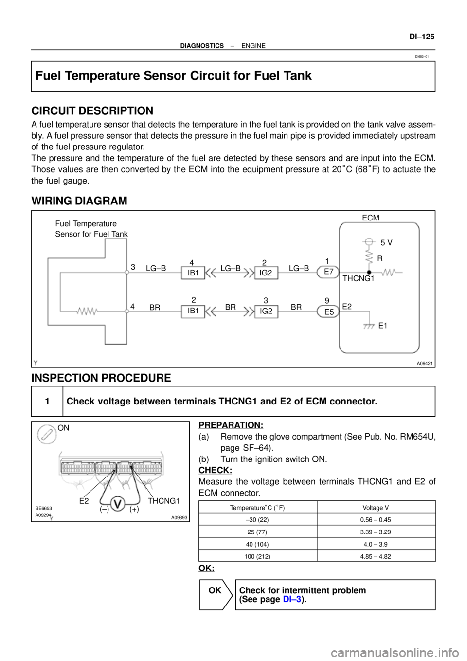
A09421
E7
E51
9ECM
5 V
THCNG1
E2
E1 R
BR 3
4
BR Fuel Temperature
Sensor for Fuel Tank
BR IB1
IG2 LG±B
IB1IG2 LG±B LG±B 42
3 2
A09294BE6653
A09393
ON
THCNG1 E2
(±) (+)
± DIAGNOSTICSENGINE
DI±125
Fuel Temperature Sensor Circuit for Fuel Tank
CIRCUIT DESCRIPTION
A fuel temperature sensor that detects the temperature in the fuel tank is provided on the tank valve assem-
bly. A fuel pressure sensor that detects the pressure in the fuel main pipe is provided immediately upstream
of the fuel pressure regulator.
The pressure and the temperature of the fuel are detected by these sensors and are input into the ECM.
Those values are then converted by the ECM into the equipment pressure at 20°C (68°F) to actuate the
the fuel gauge.
WIRING DIAGRAM
INSPECTION PROCEDURE
1 Check voltage between terminals THCNG1 and E2 of ECM connector.
PREPARATION:
(a) Remove the glove compartment (See Pub. No. RM654U,
page SF±64).
(b) Turn the ignition switch ON.
CHECK:
Measure the voltage between terminals THCNG1 and E2 of
ECM connector.
Temperature°C (°F)Voltage V
±30 (22)0.56 ± 0.45
25 (77)3.39 ± 3.29
40 (104)4.0 ± 3.9
100 (212)4.85 ± 4.82
OK:
OK Check for intermittent problem
(See page DI±3).
DI652±01
Page 2278 of 4592
DI±126
± DIAGNOSTICSENGINE
NG
2 Check fuel pressure sensor for fuel tank (See page SF±40).
NG Replace fuel pressure sensor for fuel tank.
OK
3 Check for open and short in harness and connector brtween ECM and fuel pres-
sure sensor for fuel tank (See page IN±29).
NG Repair or replace harness or connector.
OK
Check and replace ECM (See page IN±29).
Page 2279 of 4592
A09422
#10
#20
#30
#40
E01
E05 E6
E6
E6
E6
E6
E6 12
11
25
24
13
26#10+
#20+
#30+
#40+ E6
E6
E6
E62
1
15
14
BR
BR
J19
J/CA
A Injector
1 2
Injector
1 2
Injector
1 2
Injector
1 2L
B±W
BR
B±R No. 1
No. 2
No. 3
No. 4G
R
L
B±W
BR
ECEC
Voltage
Booster
Circuit
Voltage
Booster
Circuit
Voltage
Booster
Circuit
Voltage
Booster
Circuit
ECM
+B
± DIAGNOSTICSENGINE
DI±127
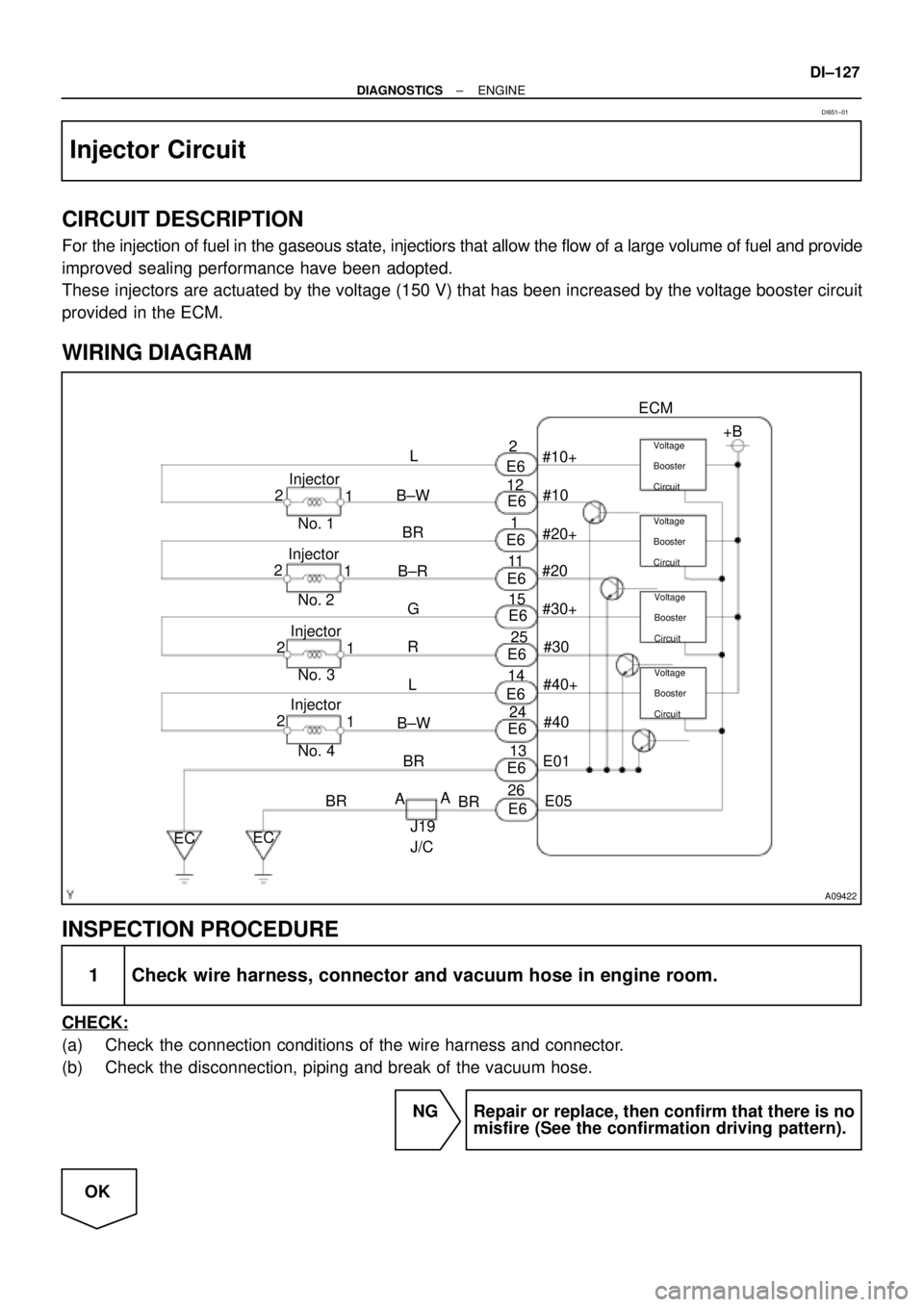
Injector Circuit
CIRCUIT DESCRIPTION
For the injection of fuel in the gaseous state, injectiors that allow the flow of a large volume of fuel and provide
improved sealing performance have been adopted.
These injectors are actuated by the voltage (150 V) that has been increased by the voltage booster circuit
provided in the ECM.
WIRING DIAGRAM
INSPECTION PROCEDURE
1 Check wire harness, connector and vacuum hose in engine room.
CHECK:
(a) Check the connection conditions of the wire harness and connector.
(b) Check the disconnection, piping and break of the vacuum hose.
NG Repair or replace, then confirm that there is no
misfire (See the confirmation driving pattern).
OK
DI651±01
Page 2280 of 4592
A09304BE6653
A09431
#10#20 ON
#30#40
(±) (+)
FI6588
FI6538
A00064
Injector Signal Waveform
10 V/
Division
GND
100 msec./Division (Idling)GND
Injection duration1 msec./Division (Idling) 10 V/
Division(Magnification)
DI±128
± DIAGNOSTICSENGINE
2 Check spark plug and spark of misfiring cylinder (See page IG±1).
NG Replace or check ignition system
(See page IG±1).
OK
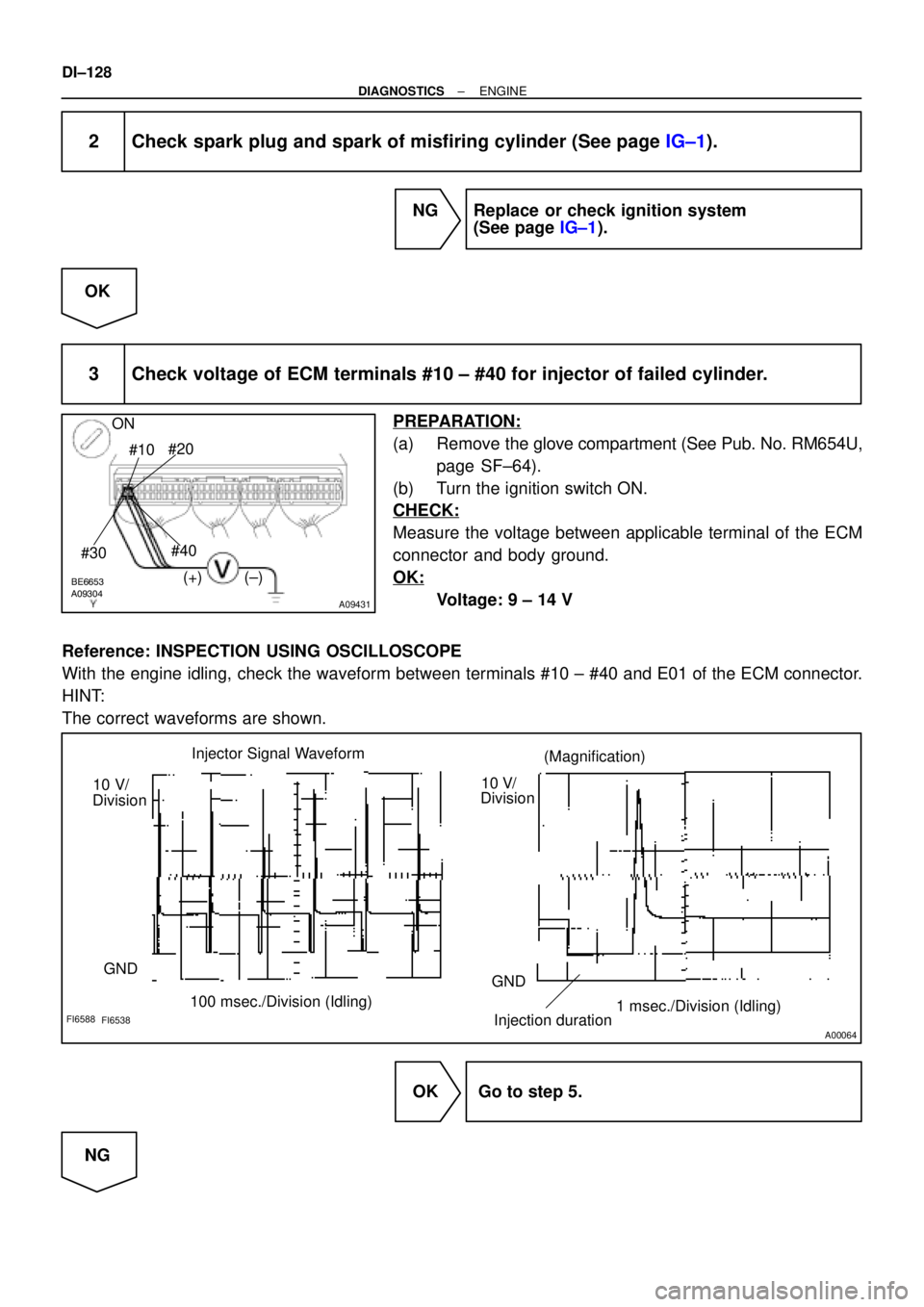
3 Check voltage of ECM terminals #10 ± #40 for injector of failed cylinder.
PREPARATION:
(a) Remove the glove compartment (See Pub. No. RM654U,
page SF±64).
(b) Turn the ignition switch ON.
CHECK:
Measure the voltage between applicable terminal of the ECM
connector and body ground.
OK:
Voltage: 9 ± 14 V
Reference: INSPECTION USING OSCILLOSCOPE
With the engine idling, check the waveform between terminals #10 ± #40 and E01 of the ECM connector.
HINT:
The correct waveforms are shown.
OK Go to step 5.
NG