TOYOTA CAMRY 2013 XV50 / 9.G Navigation Manual
Manufacturer: TOYOTA, Model Year: 2013, Model line: CAMRY, Model: TOYOTA CAMRY 2013 XV50 / 9.GPages: 336, PDF Size: 7.37 MB
Page 291 of 336
291
1. REAR VIEW MONITOR SYSTEM
9
PERIPHERAL MONITORING SYSTEM
CAUTION
●Do not use system in the following
cases:
• On icy or slick road surfaces, or in
snow
• When using tire chains or emergency
tires
• When the trunk is not closed com- pletely
• On roads that are not flat or straight, such as curves or slopes.
● In low temperatures, the screen may
darken or the image may become faint.
The image could distort when the vehi-
cle is moving, or you may become
unable to see the image on the screen.
Be sure to visually check all around the
vehicle both directly and using the mir-
rors before proceeding.
● If the tire sizes are changed, the position
of the fixed guide lines displayed on the
screen may change.
● The camera uses a special lens. The
distances between objects and pedestri-
ans that appear in the image displayed
on the screen will differ from the actual
distances. (See page 295.)
Page 292 of 336
292
1. REAR VIEW MONITOR SYSTEM
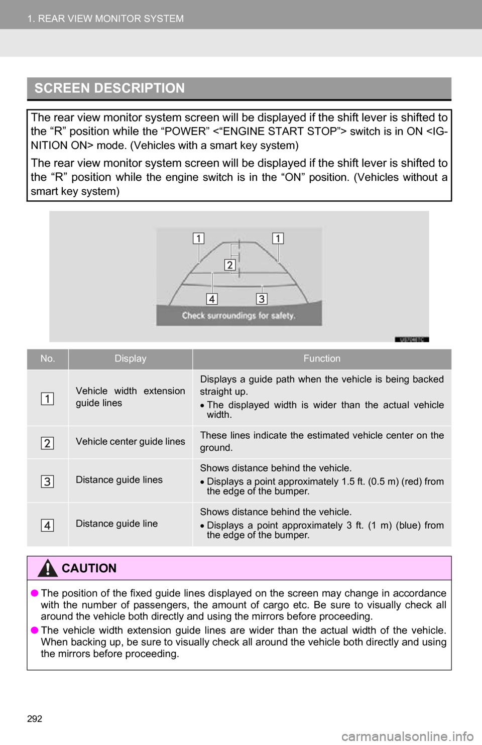
SCREEN DESCRIPTION
The rear view monitor system screen will be displayed if the shift lever is shifted to
the “R” position while
the “POWER” <“ENGINE START STOP”> switch is in ON
The rear view monitor system screen will be displayed if the shift lever is shifted to
the “R” position while
the engine switch is in the “ON” position. (Vehicles without a
smart key system)
No.DisplayFunction
Vehicle width extension
guide linesDisplays a guide path when the vehicle is being backed
straight up.
The displayed width is wider than the actual vehicle
width.
Vehicle center guide linesThese lines indicate the esti mated vehicle center on the
ground.
Distance guide linesShows distance behind the vehicle.
Displays a point approximately 1.5 ft. (0.5 m) (red) from
the edge of the bumper.
Distance guide lineShows distance behind the vehicle.
Displays a point approximately 3 ft. (1 m) (blue) from
the edge of the bumper.
CAUTION
● The position of the fixed guide lines displayed on the screen may change in accordance
with the number of passengers, the amount of cargo etc. Be sure to visually check all
around the vehicle both directly and using the mirrors before proceeding.
● The vehicle width extension guide lines are wider than the actual width of the vehicle.
When backing up, be sure to visually check all around the vehicle both directly and using
the mirrors before proceeding.
Page 293 of 336
293
1. REAR VIEW MONITOR SYSTEM
9
PERIPHERAL MONITORING SYSTEM
When the shift lever is shifted to the “R” position and any mode button (such as
“MAP/VOICE” ) is pressed
The rear view monitor system is canceled , and the screen is switched to the mode
of the button that was pressed.
CANCELING REAR VIEW MONITOR SYSTEM
The rear view monitor system is canceled when the shift lever is shifted into any
position other than the “R” position.
Page 294 of 336
294
1. REAR VIEW MONITOR SYSTEM
2. REAR VIEW MONITOR SYSTEM PRECAUTIONS
The image adjustment procedure for the
rear view monitor system screen is the
same as the procedure for adjusting the
navigation screen. (See page 32.)
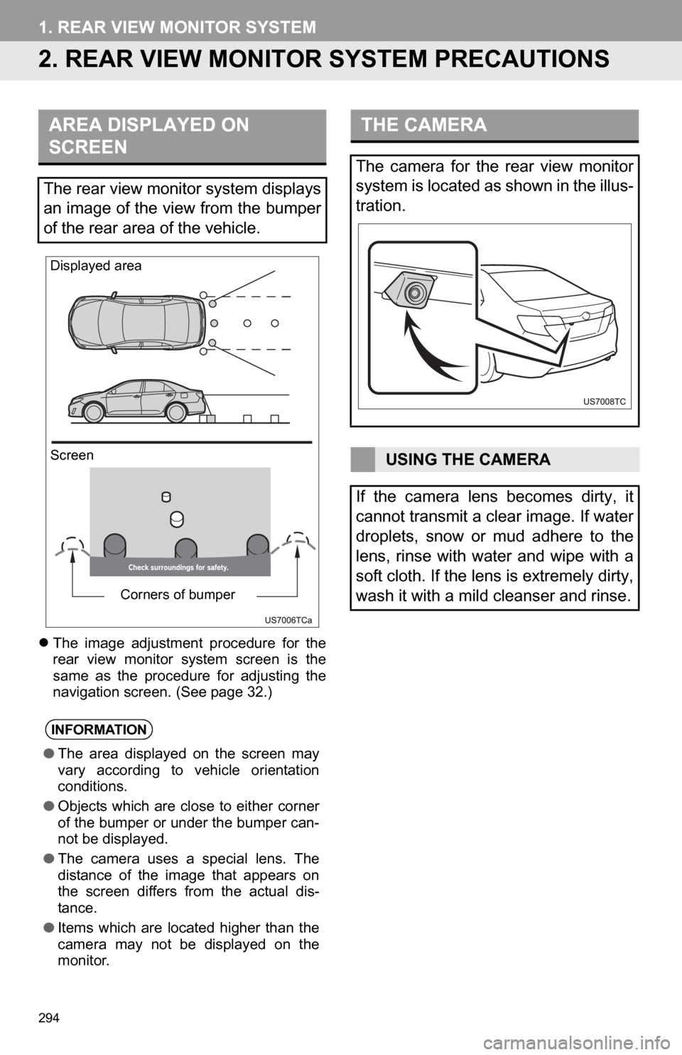
AREA DISPLAYED ON
SCREEN
The rear view monitor system displays
an image of the view from the bumper
of the rear area of the vehicle.
INFORMATION
● The area displayed on the screen may
vary according to vehicle orientation
conditions.
● Objects which are close to either corner
of the bumper or under the bumper can-
not be displayed.
● The camera uses a special lens. The
distance of the image that appears on
the screen differs from the actual dis-
tance.
● Items which are located higher than the
camera may not be displayed on the
monitor.
Screen Displayed area
Corners of bumper
THE CAMERA
The camera for the rear view monitor
system is located as shown in the illus-
tration.
USING THE CAMERA
If the camera lens becomes dirty, it
cannot transmit a clear image. If water
droplets, snow or mud adhere to the
lens, rinse with water and wipe with a
soft cloth. If the lens is extremely dirty,
wash it with a mild cleanser and rinse.
Page 295 of 336
295
1. REAR VIEW MONITOR SYSTEM
9
PERIPHERAL MONITORING SYSTEM
The distance guide lines and the vehicle
width extension guide lines may not actu-
ally be parallel with the dividing lines of the
parking space, even when they appear to
be so. Be sure to check visually.
The distances between the vehicle width
extension guide lines and the left and right
dividing lines of the parking space may not
be equal, even when they appear to be
so. Be sure to check visually.
The distance guide lines give a distance
guide for flat road surfaces. In any of the
following situations, there is a margin of
error between the fixed guide lines on the
screen and the actual distance /course on
the road.
NOTICE
● The rear view monitor system may not
operate properly in the following cases,
or if the precautions described below are
not followed.
• If the back of the vehicle is hit, the
position and mounting angle of the
camera may change.
• As the camera has a water proof con-
struction, do not detach, disassemble
or modify it. This may cause incorrect
operation.
• Do not strongly rub the camera lens. If the camera lens is scratched, it cannot
transmit a clear image.
• Do not allow organic solvent, car wax, window cleaner or glass coat to adhere
to the camera. If this happens, wipe it
off as soon as possible.
• If the temperature changes rapidly,
such as when hot water is poured on
the vehicle in cold weather, the system
may not operate normally.
• When washing the vehicle, do not apply intensive bursts of water to the
camera or camera area. Doing so may
result in the camera malfunctioning.
● Do not expose the camera to strong
impact as this could cause a malfunc-
tion. If this happens, have the vehicle
inspected by your Toyota dealer as soon
as possible.
DIFFERENCES BETWEEN
THE SCREEN AND THE
ACTUAL ROAD
Page 296 of 336
296
1. REAR VIEW MONITOR SYSTEM
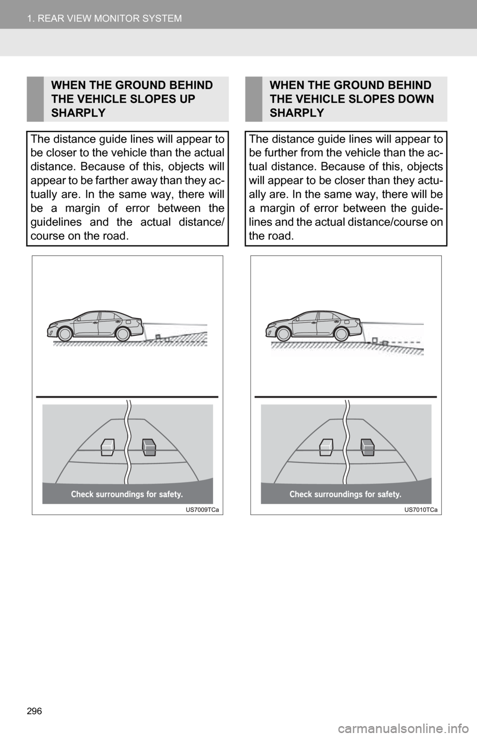
WHEN THE GROUND BEHIND
THE VEHICLE SLOPES UP
SHARPLY
The distance guide lines will appear to
be closer to the vehicle than the actual
distance. Because of this, objects will
appear to be farther away than they ac-
tually are. In the same way, there will
be a margin of error between the
guidelines and the actual distance/
course on the road.WHEN THE GROUND BEHIND
THE VEHICLE SLOPES DOWN
SHARPLY
The distance guide lines will appear to
be further from the vehicle than the ac-
tual distance. Because of this, objects
will appear to be closer than they actu-
ally are. In the same way, there will be
a margin of error between the guide-
lines and the actual distance/course on
the road.
Page 297 of 336
297
1. REAR VIEW MONITOR SYSTEM
9
PERIPHERAL MONITORING SYSTEM
Vehicle width extension guide lines
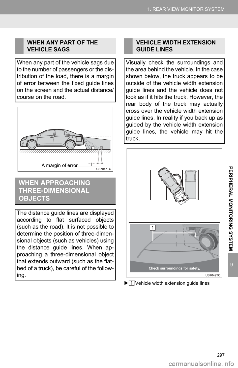
WHEN ANY PART OF THE
VEHICLE SAGS
When any part of the vehicle sags due
to the number of passengers or the dis-
tribution of the load, there is a margin
of error between the fixed guide lines
on the screen and the actual distance/
course on the road.
WHEN APPROACHING
THREE-DIMENSIONAL
OBJECTS
The distance guide lines are displayed
according to flat surfaced objects
(such as the road). It is not possible to
determine the position of three-dimen-
sional objects (such as vehicles) using
the distance guide lines. When ap-
proaching a three-dimensional object
that extends outward (such as the flat-
bed of a truck), be careful of the follow-
ing.
A margin of error
VEHICLE WIDTH EXTENSION
GUIDE LINES
Visually check the surroundings and
the area behind the vehicle. In the case
shown below, the truck appears to be
outside of the vehicle width extension
guide lines and the vehicle does not
look as if it hits the truck. However, the
rear body of the truck may actually
cross over the vehicle width extension
guide lines. In reality if you back up as
guided by the vehicle width extension
guide lines, the vehicle may hit the
truck.
Page 298 of 336
298
1. REAR VIEW MONITOR SYSTEM
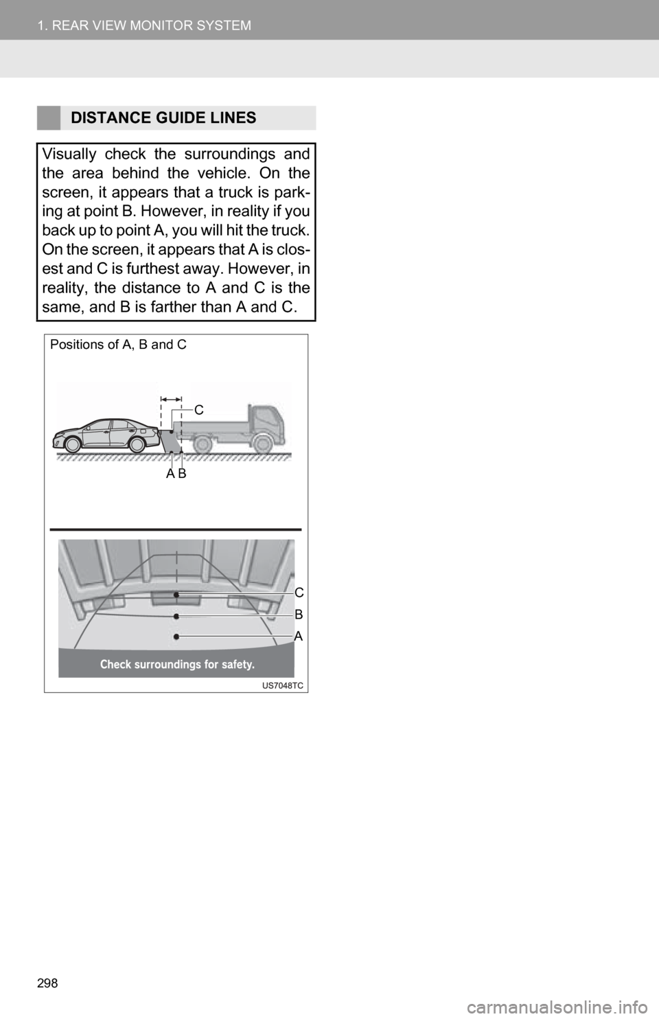
DISTANCE GUIDE LINES
Visually check the surroundings and
the area behind the vehicle. On the
screen, it appears that a truck is park-
ing at point B. However, in reality if you
back up to point A, you will hit the truck.
On the screen, it appears that A is clos-
est and C is furthest away. However, in
reality, the distance to A and C is the
same, and B is farther than A and C.
Positions of A, B and C
C
A B
C
AB
Page 299 of 336
299
1. REAR VIEW MONITOR SYSTEM
9
PERIPHERAL MONITORING SYSTEM
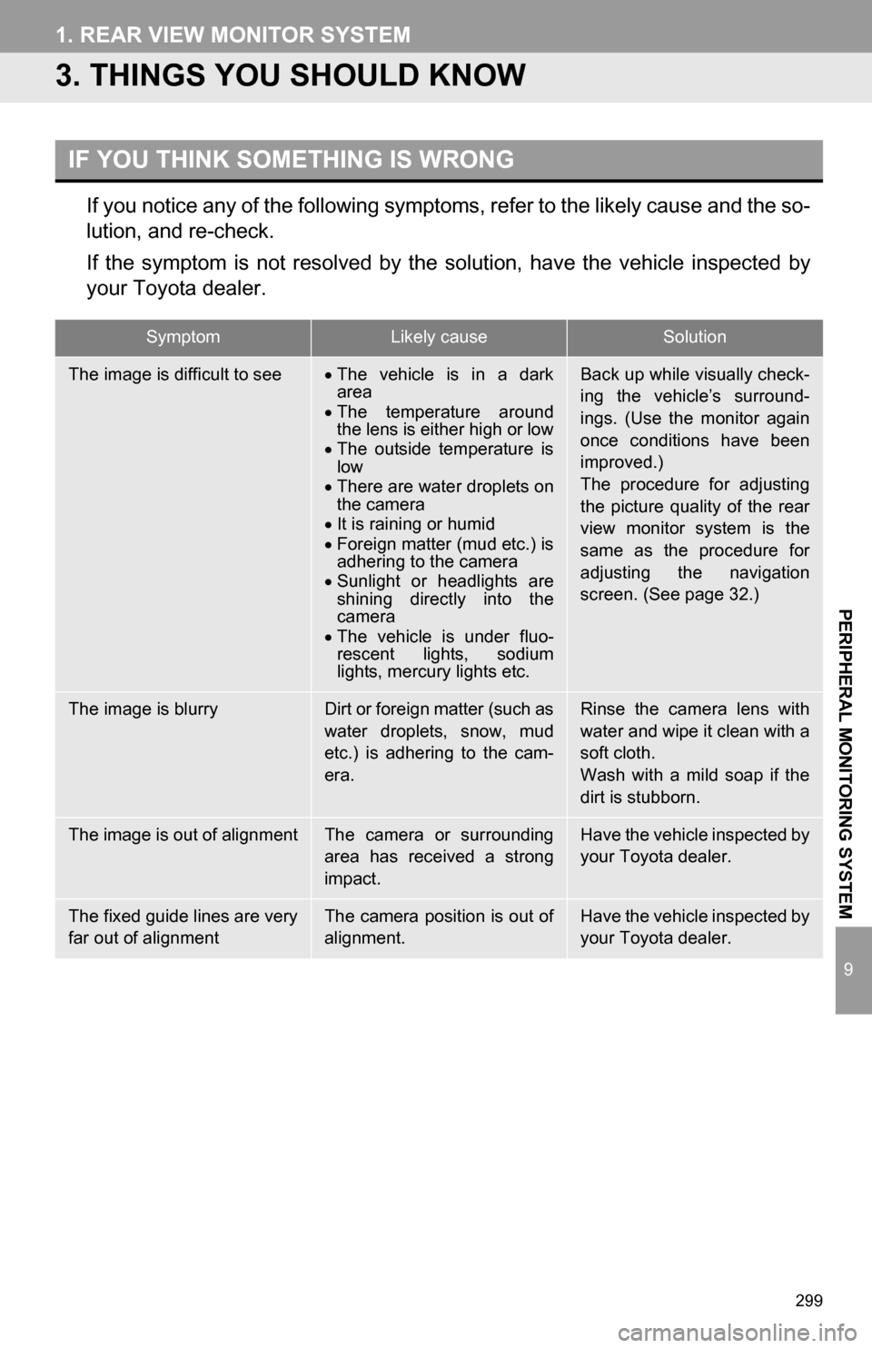
3. THINGS YOU SHOULD KNOW
If you notice any of the following symptoms, refer to the likely cause and the so-
lution, and re-check.
If the symptom is not resolved by the solution, have the vehicle inspected by
your Toyota dealer.
IF YOU THINK SOMETHING IS WRONG
SymptomLikely causeSolution
The image is difficult to seeThe vehicle is in a dark
area
The temperature around
the lens is either high or low
The outside temperature is
low
There are water droplets on
the camera
It is raining or humid
Foreign matter (mud etc.) is
adhering to the camera
Sunlight or headlights are
shining directly into the
camera
The vehicle is under fluo-
rescent lights, sodium
lights, mercury lights etc.Back up while visually check-
ing the vehicle’s surround-
ings. (Use the monitor again
once conditions have been
improved.)
The procedure for adjusting
the picture quality of the rear
view monitor system is the
same as the procedure for
adjusting the navigation
screen. (See page 32.)
The image is blurryDirt or foreign matter (such as
water droplets, snow, mud
etc.) is adhering to the cam-
era.Rinse the camera lens with
water and wipe it clean with a
soft cloth.
Wash with a mild soap if the
dirt is stubborn.
The image is out of alignmentThe camera or surrounding
area has received a strong
impact.Have the vehicle inspected by
your Toyota dealer.
The fixed guide lines are very
far out of alignmentThe camera position is out of
alignment.Have the vehicle inspected by
your Toyota dealer.
Page 300 of 336
300
1. REAR VIEW MONITOR SYSTEM