brake TOYOTA CAMRY HYBRID 2010 XV40 / 8.G Workshop Manual
[x] Cancel search | Manufacturer: TOYOTA, Model Year: 2010, Model line: CAMRY HYBRID, Model: TOYOTA CAMRY HYBRID 2010 XV40 / 8.GPages: 497, PDF Size: 9.63 MB
Page 418 of 497
5
When trouble arises
417
5-2. Steps to take in an emergency
If you have a flat tire
Remove the flat tire and replace it with the spare provided.
■Before jacking up the vehicle
●Stop the vehicle on a hard, flat surface.
● Set the parking brake.
● Shift the shift lever to P.
● Stop the hybrid system.
● Turn on the emergency flashers.
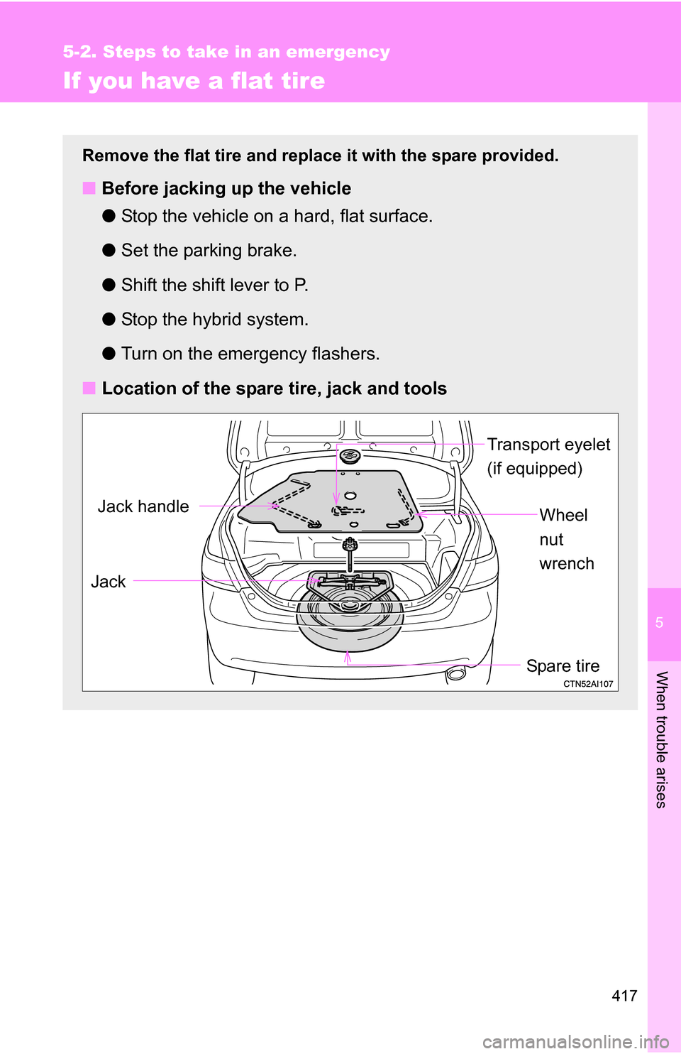
■ Location of the spare tire, jack and tools
Transport eyelet
(if equipped)
Spare tire
Jack
Wheel
nut
wrenchJack handle
Page 426 of 497
5
When trouble arises
425
5-2. Steps to take in an emergency
CAUTION
■Speed limit when using the compact spare tire
Do not drive at speeds in excess of 50 mph (80 km/h) when a compact
spare tire is installed on the vehicle.
The compact spare tire is not designed
for driving at high speeds. Failing
to observe this precaution may lead to an accident causing death or seri-
ous injury.
■When the compact spare tire is attached
The vehicle speed may not be correctly detected, and the following sys-
tems may not operate correctly:
●ABS
●Brake assist
●VSC
●TRAC
●VDIM
●Navigation system (if equipped)
Page 429 of 497
428 5-2. Steps to take in an emergency
Emergency start function
When the hybrid system does not start, the following steps can be
used as an interim measure to start the hybrid system if the
“POWER” switch is functioning normally.Set the parking brake.
Shift the shift lever to P.
Turn the “POWER” switch to ACCESSORY mode.
Press and hold the “POWER” switch for about 15 seconds
while depressing the brake pedal firmly.
Even if the hybrid system can be started using the above steps, the
system may be malfunctioning. Ha ve the vehicle checked by your
Toyota dealer.
■ The interior lights and headlights do not turn on, or the horn
does not sound.
One of the following may be the cause of the problem.
●One or both of the 12-volt ba ttery terminals may be discon-
nected.
● The 12-volt battery may be discharged. ( P. 434)
● There may be a malfunction in the steering lock system.
Contact your Toyota dealer if the problem cannot be repaired, or if
repair procedures are unknown.
STEP1
STEP2
STEP3
STEP4
Page 430 of 497
5
When trouble arises
429
5-2. Steps to take in an emergency
If the shift lever cannot be shifted from P
If the shift lever cannot be shifted with your foot on the brake, there
may be a problem with the shift lock system (a system to prevent
accidental operation of the shift lever). Have the vehicle inspected by
your Toyota dealer.
The following steps may be used as an emergency measure to
ensure that the shift lever can be shifted.
Set the parking brake.
Turn the “POWER” switch to ACCESSORY mode.
Depress the brake pedal.
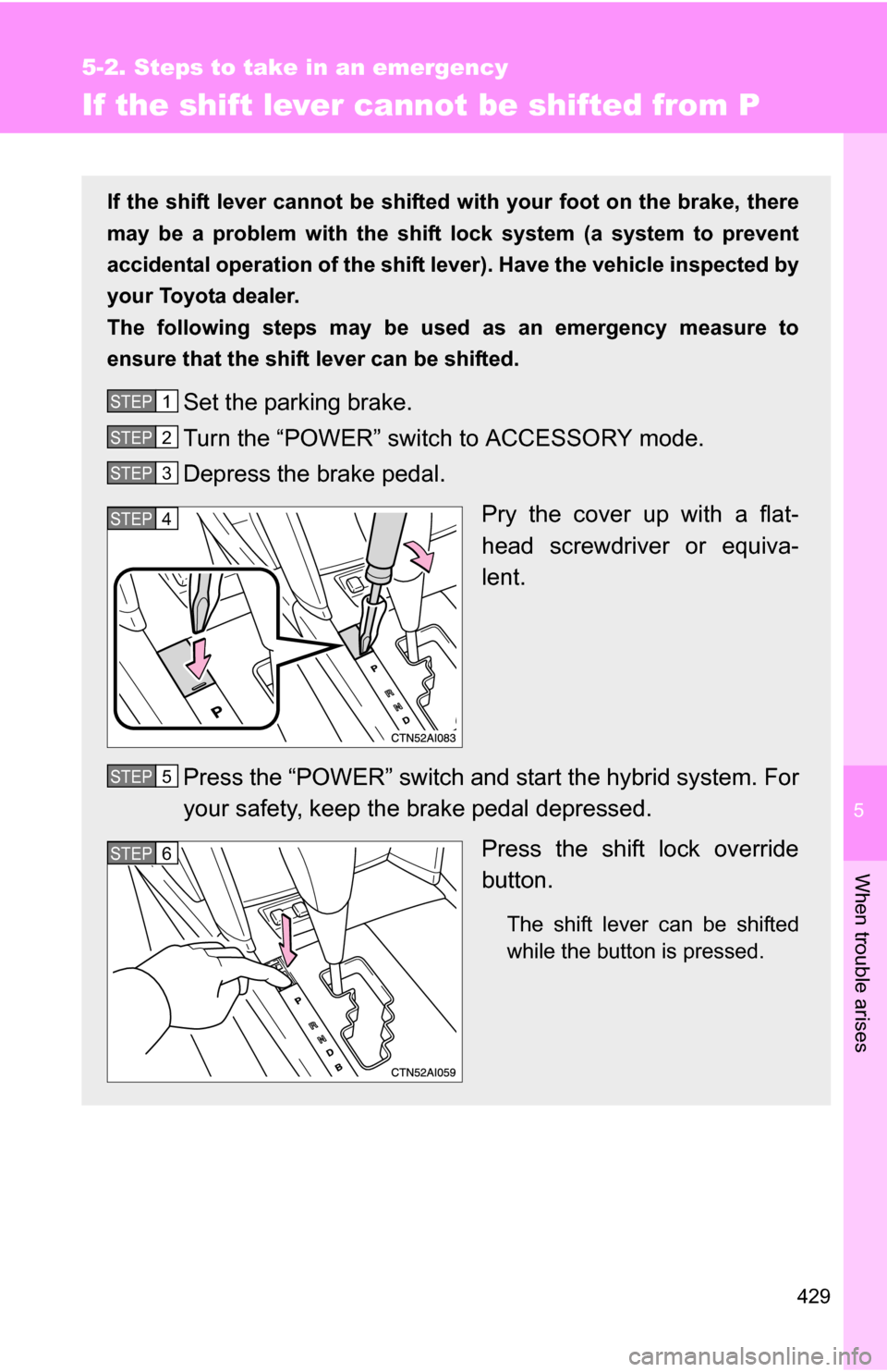
Pry the cover up with a flat-
head screwdriver or equiva-
lent.
Press the “POWER” switch and start the hybrid system. For
your safety, keep the brake pedal depressed. Press the shift lock override
button.
The shift lever can be shifted
while the button is pressed.
STEP1
STEP2
STEP3
STEP4
STEP5
STEP6
Page 433 of 497
432 5-2. Steps to take in an emergency
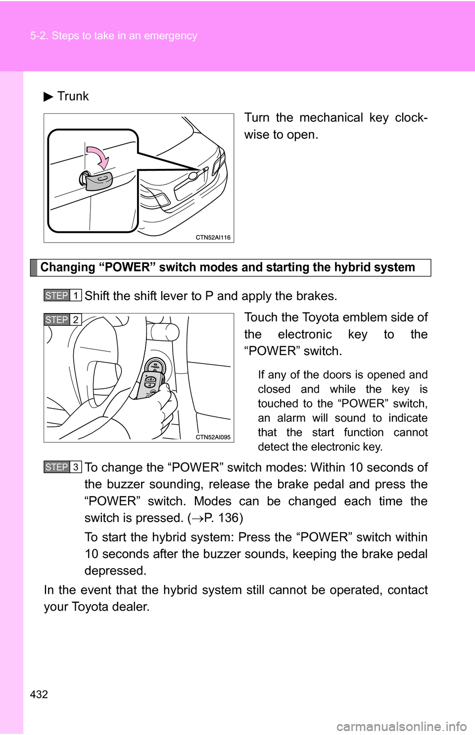
TrunkTurn the mechanical key clock-
wise to open.
Changing “POWER” switch modes and starting the hybrid system
Shift the shift lever to P and apply the brakes.Touch the Toyota emblem side of
the electronic key to the
“POWER” switch.
If any of the doors is opened and
closed and while the key is
touched to the “POWER” switch,
an alarm will sound to indicate
that the start function cannot
detect the electronic key.
To change the “POWER” switch modes: Within 10 seconds of
the buzzer sounding, release t he brake pedal and press the
“POWER” switch. Modes can be changed each time the
switch is pressed. ( P. 136)
To start the hybrid system: Press the “POWER” switch within
10 seconds after the buzzer s ounds, keeping the brake pedal
depressed.
In the event that the hybrid system still cannot be operated, contact
your Toyota dealer.
STEP1
STEP2
STEP3
Page 443 of 497
442
5-2. Steps to take in an emergency
If the vehicle becomes stuck
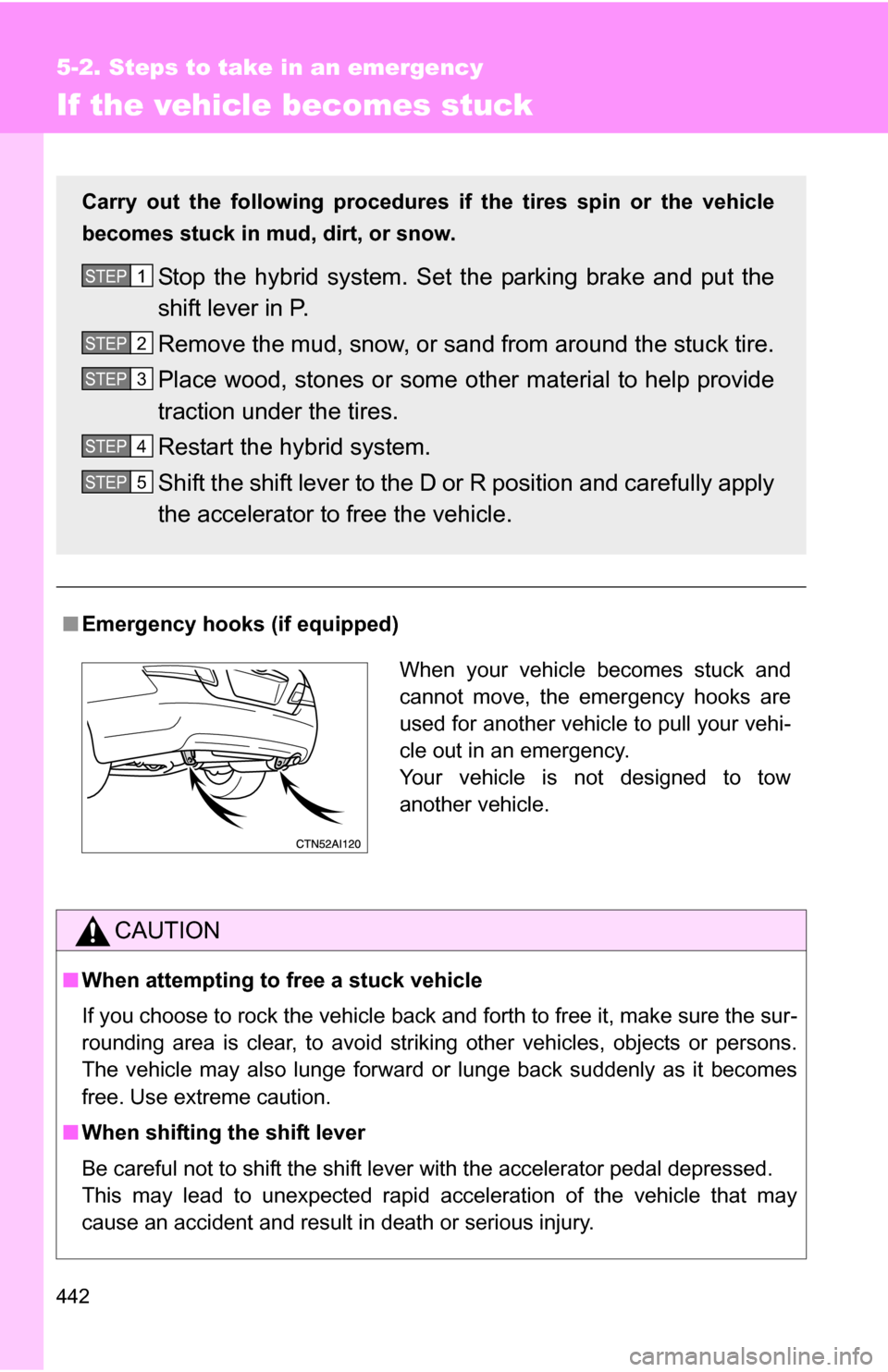
■Emergency hooks (if equipped)
CAUTION
■When attempting to free a stuck vehicle
If you choose to rock the vehicle back and forth to free it, make sure the sur-
rounding area is clear, to avoid striki ng other vehicles, objects or persons.
The vehicle may also lunge forward or lunge back suddenly as it becomes
free. Use extreme caution.
■ When shifting the shift lever
Be careful not to shift the shift lever with the accelerator pedal depressed.
This may lead to unexpected rapid acceleration of the vehicle that may
cause an accident and result in death or serious injury.
Carry out the following procedures if the tires spin or the vehicle
becomes stuck in mud, dirt, or snow.
Stop the hybrid system. Set t he parking brake and put the
shift lever in P.
Remove the mud, snow, or sand from around the stuck tire.
Place wood, stones or some other material to help provide
traction under the tires.
Restart the hybrid system.
Shift the shift lever to the D or R position and carefully apply
the accelerator to free the vehicle.STEP1
STEP2
STEP3
STEP4
STEP5
When your vehicle becomes stuck and
cannot move, the emergency hooks are
used for another vehicle to pull your vehi-
cle out in an emergency.
Your vehicle is not designed to tow
another vehicle.
Page 453 of 497
452 6-1. Specifications
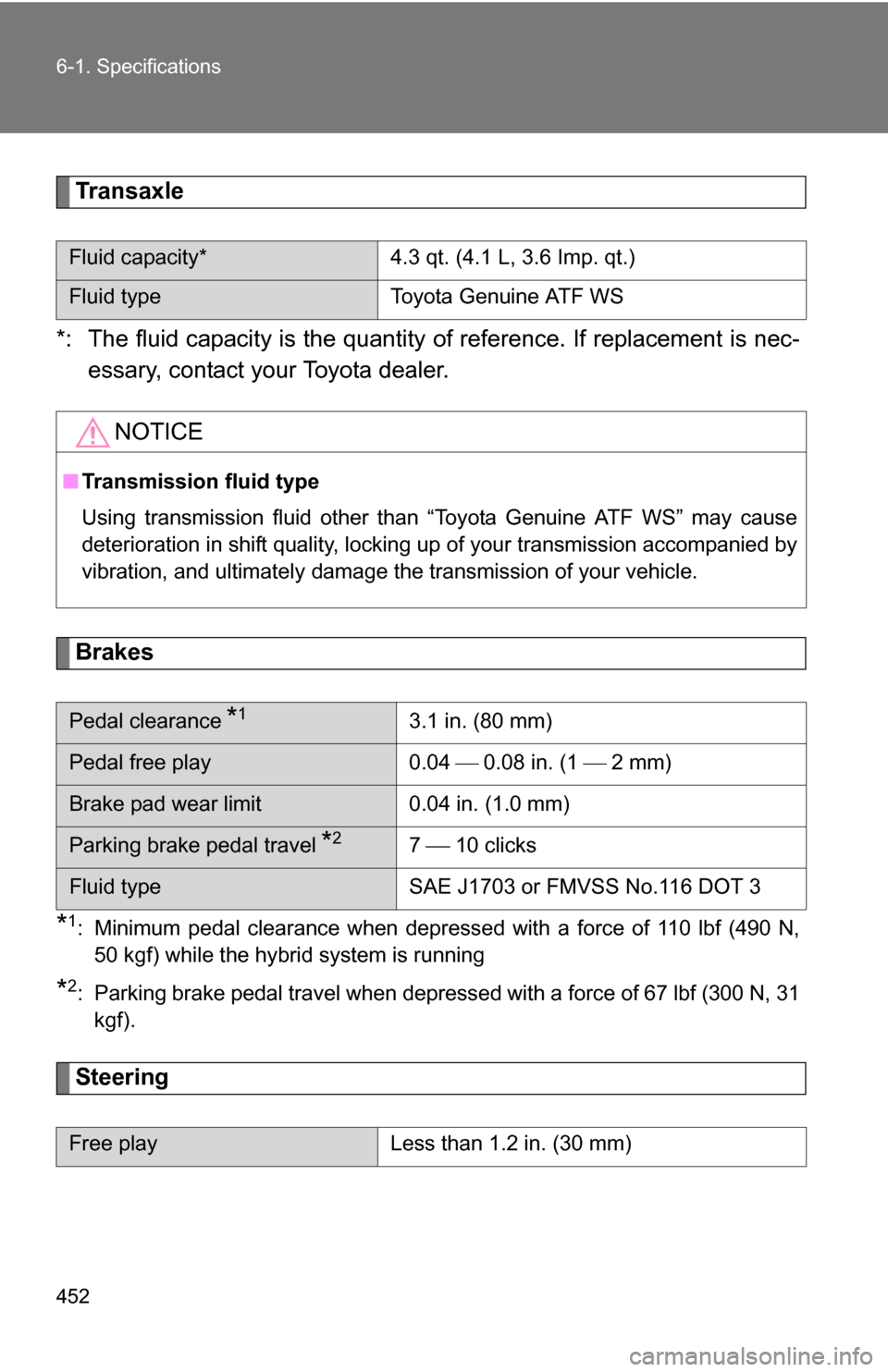
Transaxle
*: The fluid capacity is the quantity of reference. If replacement is nec-
essary, contact your Toyota dealer.
Brakes
*1: Minimum pedal clearance when depressed with a force of 110 lbf (490 N, 50 kgf) while the hybrid system is running
*2: Parking brake pedal travel when depressed with a force of 67 lbf (300 N, 31kgf).
Steering
Fluid capacity* 4.3 qt. (4.1 L, 3.6 Imp. qt.)
Fluid type Toyota Genuine ATF WS
NOTICE
■Transmission fluid type
Using transmission fluid other than “Toyota Genuine ATF WS” may cause
deterioration in shift quality, locking up of your transmission accompanied by
vibration, and ultimately damage the transmission of your vehicle.
Pedal clearance *13.1 in. (80 mm)
Pedal free play 0.04 0.08 in. (1 2 mm)
Brake pad wear limit 0.04 in. (1.0 mm)
Parking brake pedal travel *27 10 clicks
Fluid type SAE J1703 or FMVSS No.116 DOT 3
Free playLess than 1.2 in. (30 mm)
Page 465 of 497
464 6-1. Specifications
Warning: The temperature grades for this tire are established for a
tire that is properly inflated and not overloaded.
Excessive speed, underinflation, or excessive loading, either sepa-
rately or in combination, can cause heat buildup and possible tire fail-
ure.
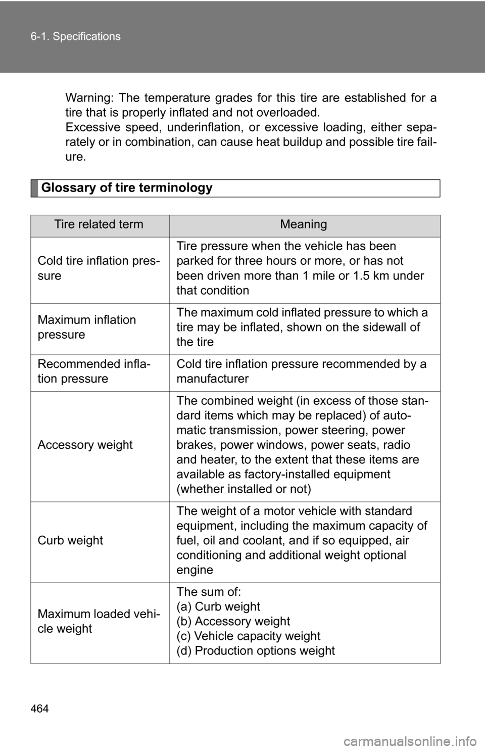
Glossary of tire terminology
Tire related termMeaning
Cold tire inflation pres-
sure Tire pressure when the vehicle has been
parked for three hours or more, or has not
been driven more than 1 mile or 1.5 km under
that condition
Maximum inflation
pressure The maximum cold inflated
pressure to which a
tire may be inflated, s hown on the sidewall of
the tire
Recommended infla-
tion pressure Cold tire inflation pressure recommended by a
manufacturer
Accessory weight The combined weight (in excess of those stan-
dard items which may be replaced) of auto-
matic transmission, power steering, power
brakes, power windows, power seats, radio
and heater, to the extent that these items are
available as factory-installed equipment
(whether installed or not)
Curb weight The weight of a motor vehicle with standard
equipment, including the maximum capacity of
fuel, oil and coolant, and if so equipped, air
conditioning and additional weight optional
engine
Maximum loaded vehi-
cle weight The sum of:
(a) Curb weight
(b) Accessory weight
(c) Vehicle capacity weight
(d) Production options weight
Page 466 of 497
465
6-1. Specifications
6
Vehicle specifications
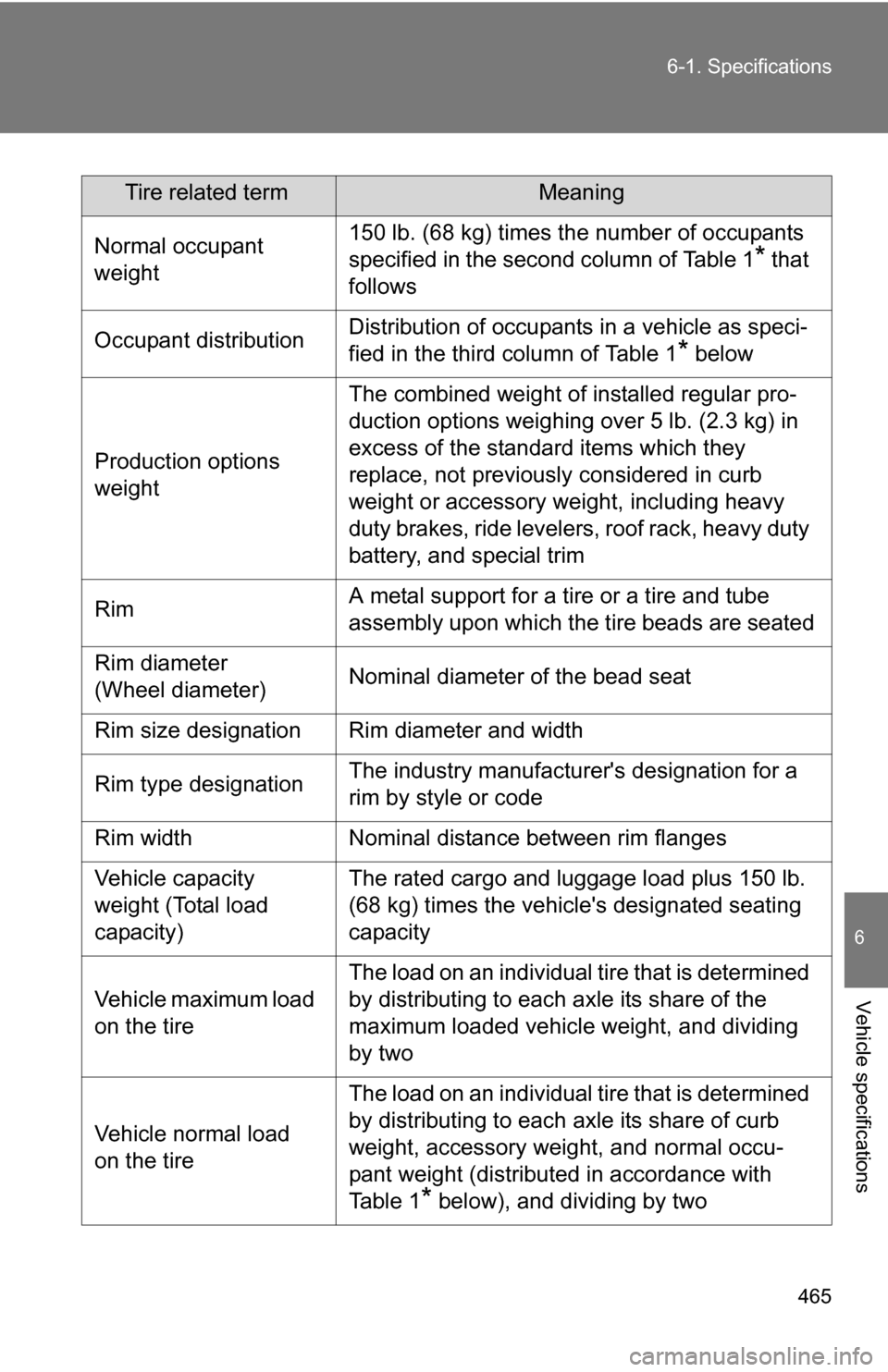
Tire related termMeaning
Normal occupant
weight 150 lb. (68 kg) times the number of occupants
specified in the second column of Table 1
* that
follows
Occupant distribution Distribution of occupants in a vehicle as speci-
fied in the third column of Table 1
* below
Production options
weight The combined weight of installed regular pro-
duction options weighing over 5 lb. (2.3 kg) in
excess of the standard items which they
replace, not previously considered in curb
weight or accessory weight, including heavy
duty brakes, ride levelers, roof rack, heavy duty
battery, and special trim
Rim A metal support for a tire or a tire and tube
assembly upon which the tire beads are seated
Rim diameter
(Wheel diameter) Nominal diameter of the bead seat
Rim size designation Rim diameter and width
Rim type designation The industry manufacturer's designation for a
rim by style or code
Rim width Nominal distance between rim flanges
Vehicle capacity
weight (Total load
capacity) The rated cargo and luggage load plus 150 lb.
(68 kg) times the vehicl
e's designated seating
capacity
Vehicle maximum load
on the tire The load on an individual tire that is determined
by distributing to each axle its share of the
maximum loaded vehicle weight, and dividing
by two
Vehicle normal load
on the tire The load on an individual tire that is determined
by distributing to each axle its share of curb
weight, accessory weight, and normal occu-
pant weight (distributed in accordance with
Ta b l e 1
* below), and dividing by two
Page 483 of 497
482
Abbreviation list
Abbreviation/Acronym list
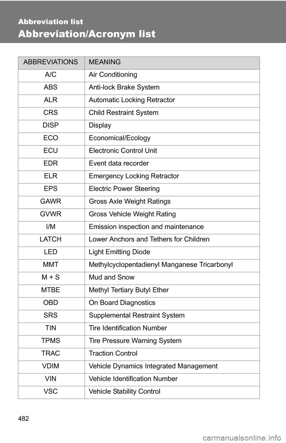
ABBREVIATIONSMEANING
A/C Air Conditioning
ABS Anti-lock Brake System ALR Automatic Locking Retractor
CRS Child Restraint System
DISP Display ECO Economical/Ecology
ECU Electronic Control Unit
EDR Event data recorder ELR Emergency Locking Retractor
EPS Electric Power Steering
GAWR Gross Axle Weight Ratings
GVWR Gross Vehicle Weight Rating I/M Emission inspection and maintenance
LATCH Lower Anchors and Tethers for Children LED Light Emitting Diode
MMT Methylcyclopentadienyl Manganese Tricarbonyl
M + S Mud and Snow
MTBE Methyl Tertiary Butyl Ether OBD On Board Diagnostics
SRS Supplemental Restraint System TIN Tire Identification Number
TPMS Tire Pressure Warning System
TRAC Traction Control VDIM Vehicle Dynamics Integrated Management VIN Vehicle Identification Number
VSC Vehicle Stability Control