ECU TOYOTA CAMRY HYBRID 2022 Manual PDF
[x] Cancel search | Manufacturer: TOYOTA, Model Year: 2022, Model line: CAMRY HYBRID, Model: TOYOTA CAMRY HYBRID 2022Pages: 624, PDF Size: 13.76 MB
Page 523 of 624

5237-2. Steps to take in an emergency
7
When trouble arises
WARNING
■When using the compact spare tire
●Remember that the compact spare tire provided is specifically
designed for use with your vehicle. Do not use your compact spare tire
on another vehicle.
●Do not use more than one compact spare tires simultaneously.
●Replace the compact spare tire with a standard tire as soon as possi-
ble.
●Avoid sudden acceleration, abrupt steering, sudden braking and shift-
ing operations that cause sudden engine braking.
■When the compact spare tire is attached
The vehicle speed may not be correctly detected, and the following sys-
tems may not operate correctly:
*:If equipped
■Speed limit when using the compact spare tire
Do not drive at speeds in excess of 50 mph (80 km/h) when a compact
spare tire is installed on the vehicle.
The compact spare tire is not designed for driving at high speeds. Fail-
ure to observe this precaution may lead to an accident causing death or
serious injury.
■After using the tools and jack
Before driving, make sure all the tools and jack are securely in place in
their storage location to reduce the possibility of personal injury during a
collision or sudden braking.
• ABS & Brake assist
• VSC
•TRAC
• EPS
• AHB (Automatic High Beam)
•AFS (Adaptive Front-lighting
System)
*
• Dynamic radar cruise control
with full-speed range
• LTA (Lane Tracing Assist)• PCS (Pre-Collision System)
• Tire pressure warning system
• BSM (Blind Spot Monitor)
*
• Intuitive parking assist*
• PKSB (Parking Support
Brake)
*
• Rear view monitor system*
• Toyota parking assist monitor*
• Panoramic view monitor*
• Navigation system*
Page 533 of 624

5337-2. Steps to take in an emergency
7
When trouble arises
■Starting the hybrid system when the 12-volt battery is discharged
The hybrid system cannot be started by push-starting.
■To prevent 12-volt battery discharge
●Turn off the headlights and the audio system while the hybrid system is off.
●Turn off any unnecessary electrical components when the vehicle is running
at a low speed for an extended period, such as in heavy traffic.
■When the 12-volt battery is removed or discharged
●Information stored in the ECU is cleared. When the 12-volt battery is
depleted, have the vehicle inspected at your Toyota dealer.
●Some systems may require initialization. (P. 577)
■When removing the 12-volt battery terminals
When the 12-volt battery terminals are removed, the information stored in the
ECU is cleared. Before removing the 12-volt battery terminals, contact your
Toyota dealer.
■Charging the 12-volt battery
The electricity stored in the 12-volt battery will discharge gradually even when
the vehicle is not in use, due to natural discharge and the draining effects of
certain electrical appliances. If the vehicle is left for a long time, the 12-volt
battery may discharge, and the hybrid system may be unable to start. (The
12-volt battery recharges automatically while the hybrid system is operating.)
■When recharging or replacing the 12-volt battery
●In some cases, it may not be possible to unlock the doors using the smart
key system when the 12-volt battery is discharged. Use the wireless remote
control or the mechanical key to lock or unlock the doors.
●The hybrid system may not start on the first attempt after the 12-volt battery
has recharged but will start normally after the second attempt. This is not a
malfunction.
●The power switch mode is memorized by the vehicle. When the 12-volt bat-
tery is reconnected, the system will return to the mode it was in before the
12-volt battery was discharged. Before disconnecting the 12-volt battery,
turn the power switch off.
If you are unsure what mode the power switch was in before the 12-volt bat-
tery discharged, be especially careful when reconnecting the 12-volt battery.
Page 534 of 624
5347-2. Steps to take in an emergency
■When replacing the 12-volt battery
●<003800560048000300440003002600480051005700550044004f000300270048004a004400560056004c0051004a00030057005c00530048000300140015001000590052004f00570003004500440057005700480055005c0003000b002800580055005200
53004800440051000300350048004a0058004f00440057004c[ons).
●Vehicles without a moon roof: Use a 12-volt battery that the case size is
same as the previous one (LN2), 20 hour rate capacity (20HR) is equivalent
(55Ah) or greater, and performance rating (CCA) is equivalent (345A) or
greater.
Vehicles with a moon roof: Use a 12-volt battery that the case size is same
as the previous one (LN2), 20 hour rate capacity (20HR) is equivalent
(60Ah) or greater, and performance rating (CCA) is equivalent (563A) or
greater.
• If the sizes differ, the 12-volt battery cannot be properly secured.
• If the 20 hour rate capacity is low, even if the time period where the vehi-
cle is not used is a short time, the 12-volt battery may discharge and the
hybrid system may not be able to start.
●Use a 12-volt battery with a handle. If a 12-volt battery without a handle is
used, removal is more difficult.
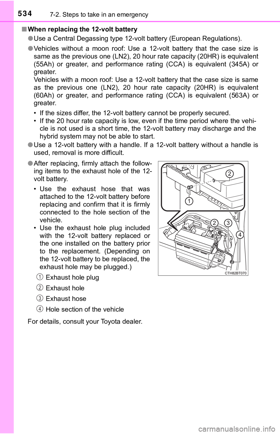
For details, consult your Toyota dealer. ●After replacing, firmly attach the follow-
ing items to the exhaust hole of the 12-
volt battery.
• Use the exhaust hose that was
attached to the 12-volt battery before
replacing and confirm that it is firmly
connected to the hole section of the
vehicle.
• Use the exhaust hole plug included
with the 12-volt battery replaced or
the one installed on the battery prior
to the replacement. (Depending on
the 12-volt battery to be replaced, the
exhaust hole may be plugged.)
Exhaust hole plug
Exhaust hole
Exhaust hose
Hole section of the vehicle
1
2
3
4
Page 536 of 624

5367-2. Steps to take in an emergency
WARNING
■When replacing the 12-volt battery
After replacing, securely attach the exhaust hose and exhaust hole plug to
the exhaust hole of the replaced 12-volt battery. If not properly installed,
gases (hydrogen) may leak into the vehicle interior, and there is the possi-
ble danger of the gas igniting and exploding.
NOTICE
■When handling jumper cables
When connecting the jumper cables, ensure that they do not become entan-
gled in the cooling fan or engine drive belt.
■To prevent damaging the vehicle
The exclusive jump starting terminal is to be used when charging the 12-volt
battery from another vehicle in an emergency. It cannot be used to jump
start another vehicle.
Page 567 of 624
5678-1. Specifications
8
Vehicle specifications
*: Table 1 Occupant loading and distribution for vehicle normal load for
various designated seating capacities
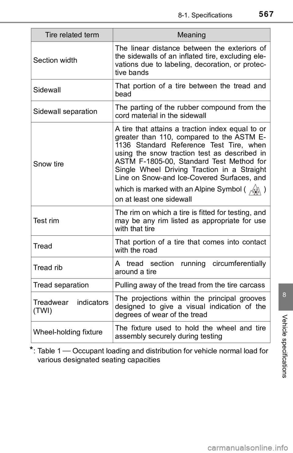
Section width
The linear distance between the exteriors of
the sidewalls of an inflated tire, excluding ele-
vations due to labeling, decoration, or protec-
tive bands
SidewallThat portion of a tire between the tread and
bead
Sidewall separationThe parting of the rubber compound from the
cord material in the sidewall
Snow tire
A tire that attains a traction index equal to or
greater than 110, compared to the ASTM E-
1136 Standard Reference Test Tire, when
using the snow traction test as described in
ASTM F-1805-00, Standard Test Method for
Single Wheel Driving Traction in a Straight
Line on Snow-and Ice-Covered Surfaces, and
which is marked with an Alpine Symbol ( )
on at least one sidewall
Te s t r i m
The rim on which a tire is fitted for testing, and
may be any rim listed as appropriate for use
with that tire
TreadThat portion of a tire that comes into contact
with the road
Tread ribA tread section running circumferentially
around a tire
Tread separationPulling away of the tread from the tire carcass
Treadwear indicators
(TWI)The projections within the principal grooves
designed to give a visual indication of the
degrees of wear of the tread
Wheel-holding fixtureThe fixture used to hold the wheel and tire
assembly securely during testing
Tire related termMeaning
Page 572 of 624
5728-2. Customization
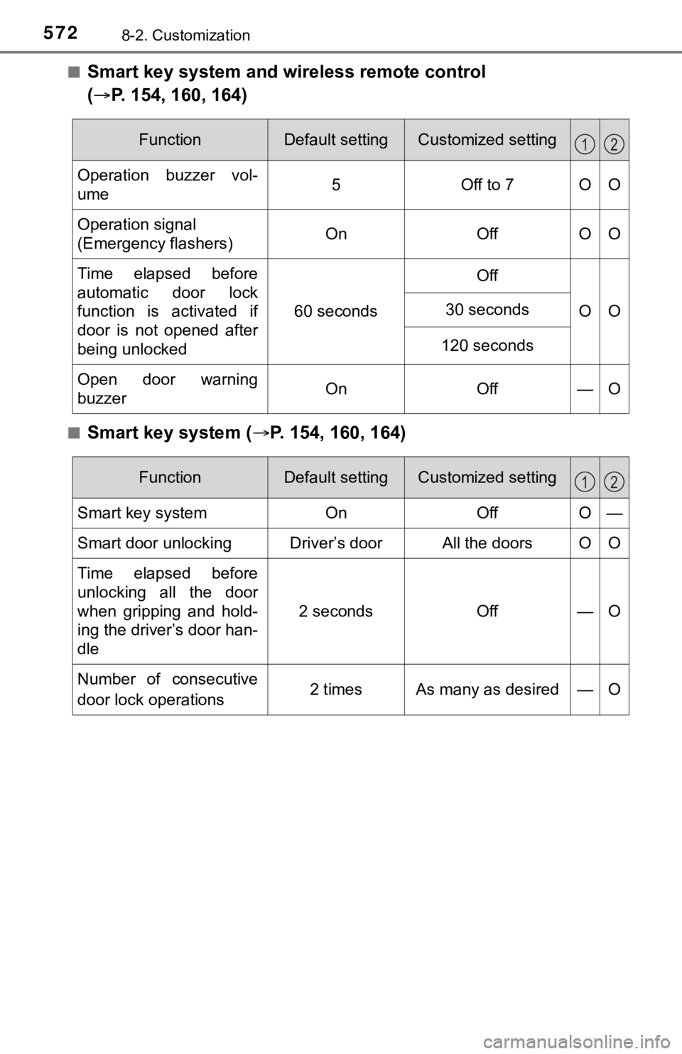
■Smart key system and wireless remote control
(P. 154, 160, 164)
■Smart key system (P. 154, 160, 164)
FunctionDefault settingCustomized setting
Operation buzzer vol-
ume5Off to 7OO
Operation signal
(Emergency flashers) On Off O O
Time elapsed before
automatic door lock
function is activated if
door is not opened after
being unlocked60 secondsOff
OO
30 seconds
120 seconds
Open door warning
buzzerOnOff —O
12
FunctionDefault settingCustomized setting
Smart key systemOnOffO—
Smart door unlockingDriver’s doorAll the doors O O
Time elapsed before
unlocking all the door
when gripping and hold-
ing the driver’s door han-
dle
2 secondsOff—O
Number of consecutive
door lock operations2 times As many as desired — O
12
Page 582 of 624
582
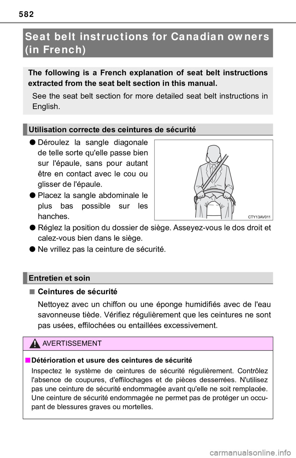
●Déroulez la sangle diagonale
de telle sorte qu'elle passe bien
sur l'épaule, sans pour autant
être en contact avec le cou ou
glisser de l'épaule.
●Placez la sangle abdominale le
plus bas possible sur les
hanches.
●Réglez la position du dossier de siège. Asseyez-vous le dos droit et
calez-vous bien dans le siège.
●Ne vrillez pas la ceinture de sécurité.
■Ceintures de sécurité
Nettoyez avec un chiffon ou une éponge humidifiés avec de l'eau
savonneuse tiède. Vérifiez régulièrement que les ceintures ne sont
pas usées, effilochées ou entaillées excessivement.
Seat belt instructions for Canadian owners
(in French)
The following is a French explanation of seat belt instructions
extracted from the seat belt section in this manual.
See the seat belt section for more detailed seat belt instructions in
English.
Utilisation correcte des ceintures de sécurité
Entretien et soin
AVERTISSEMENT
■Détérioration et usure des ceintures de sécurité
Inspectez le système de ceintures de sécurité régulièrement. Contrôlez
l'absence de coupures, d'effilochages et de pièces desserrées. N'utilisez
pas une ceinture de sécurité endommagée avant qu'elle ne soit remplacée.
Une ceinture de sécurité endommagée ne permet pas de protéger un occu-
pant de blessures graves ou mortelles.
Page 585 of 624
585
9
For owners
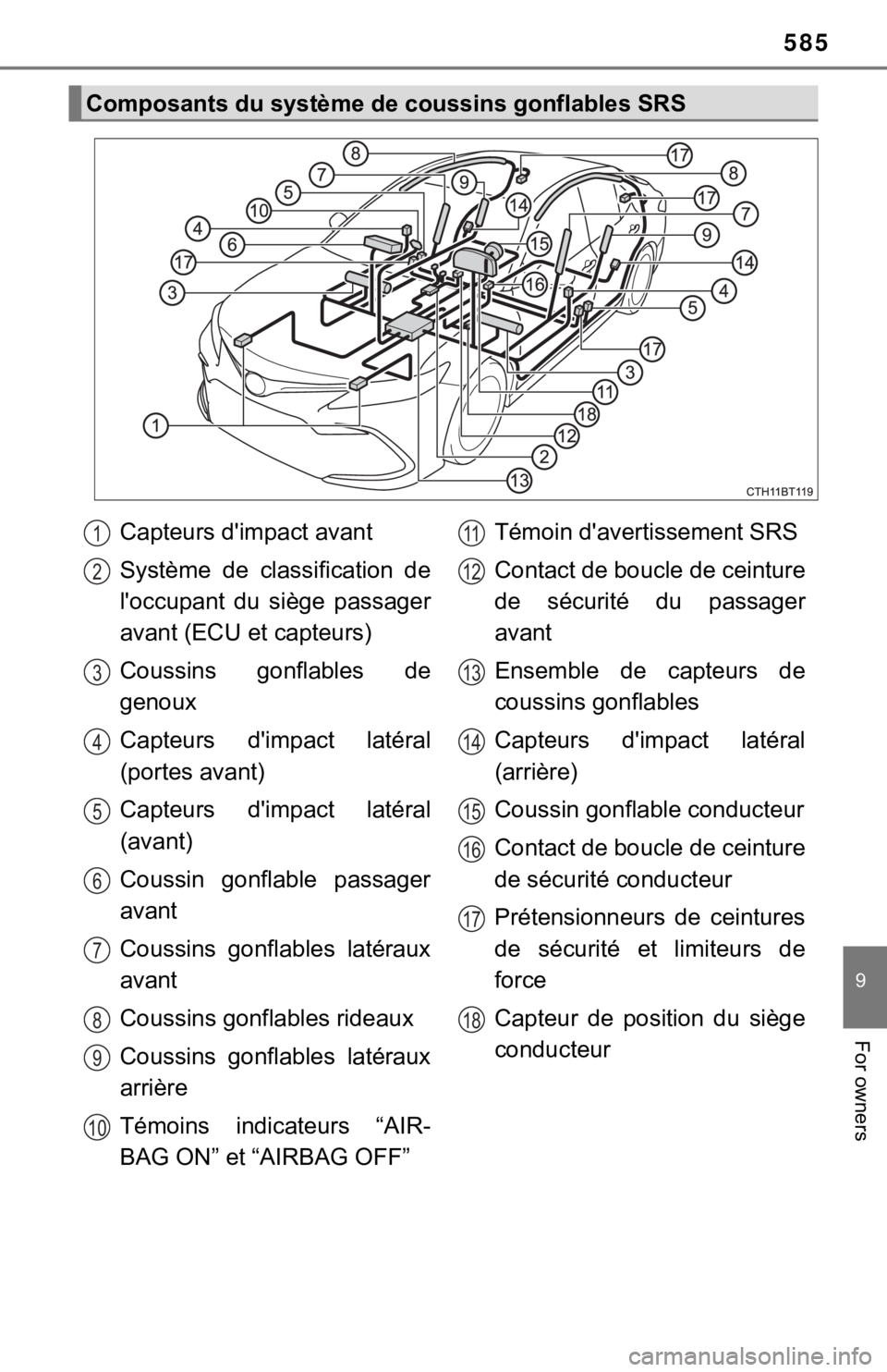
Composants du système de coussins gonflables SRS
Capteurs d'impact avant
Système de classification de
l'occupant du siège passager
avant (ECU et capteurs)
Coussins gonflables de
genoux
Capteurs d'impact latéral
(portes avant)
Capteurs d'impact latéral
(avant)
Coussin gonflable passager
avant
Coussins gonflables latéraux
avant
Coussins gonflables rideaux
Coussins gonflables latéraux
arrière
Témoins indicateurs “AIR-
BAG ON” et “AIRBAG OFF”Témoin d'avertissement SRS
Contact de boucle de ceinture
de sécurité du passager
avant
Ensemble de capteurs de
coussins gonflables
Capteurs d'impact latéral
(arrière)
Coussin gonflable conducteur
Contact de boucle de ceinture
de sécurité conducteur
Prétensionneurs de ceintures
de sécurité et limiteurs de
force
Capteur de position du siège
conducteur1
2
3
4
5
6
7
8
9
10
11
12
13
14
15
16
17
18
Page 586 of 624

586
Votre véhicule est équipé de COUSSINS GONFLABLES INTELLI-
GENTS conçus selon les normes de sécurité américaines applicables
aux véhicules à moteur (FMVSS208). L'ensemble de capteurs de
coussins gonflables (ECU) régule le déploiement des coussins gon-
flables sur la base des informations qu'il reçoit des capteurs, etc., indi-
qués ci-dessus dans le schéma illustrant les composants du système.
Parmi ces informations figurent la gravité du choc et l'occupation du
véhicule par les passagers. Le déploiement rapide des coussins gon-
flables est obtenu au moyen d'une réaction chimique dans les disposi-
tifs pyrotechniques, qui produit un gaz inoffensif permettant d'amortir
le mouvement des occupants.
Page 587 of 624

587
9
For owners
AVERTISSEMENT
■Précautions relatives aux coussins gonflables SRS
Respectez les précautions suivantes concernant les coussins gonflables
SRS.
Le non-respect de ces précautions peut occasionner des blessures graves,
voire mortelles.
●Le conducteur et tous les passagers du véhicule doivent porter correcte-
ment leur ceinture de sécurité.
Les coussins gonflables SRS sont des dispositifs supplémentaires à utili-
ser avec les ceintures de sécurité.
●Le coussin gonflable conducteur SRS se déploie avec une force considé-
rable, pouvant occasionner des blessures graves, voire mortelles, si le
conducteur se trouve très près du coussin gonflable. L'autorité fédérale
chargée de la sécurité routière aux États-Unis (NHTSA) conseille:
La zone à risque du coussin gonflable conducteur se situant dans les pre-
miers 2 à 3 in. (50 à 75 mm) de déploiement, vous placer à 10 in. (250
mm) de votre coussin gonflable conducteur vous garantit une marge de
sécurité suffisante. Cette distance est à mesurer entre le centre du volant
et le sternum. Si vous êtes assis à moins de 10 in. (250 mm), vous pou-
vez changer votre position de conduite de plusieurs façons:
• Reculez votre siège le plus possible, de manière à pouvoir encore
atteindre confortablement les pédales.
• Inclinez légèrement le dossier du siège.
Bien que les véhicules aient une conception différente, un grand
nombre de conducteurs peuvent s'asseoir à une distance de 10 in. (250
mm), même avec le siège conducteur complètement avancé, simple-
ment en inclinant un peu le dossier de siège. Si vous avez des difficul-
tés à voir la route après avoir incliné le dossier de votre siège, utilisez
un coussin ferme et antidérapant pour vous rehausser ou remontez le
<0056004c0071004a004800030056004c000300590052005700550048000300590070004b004c00460058004f004800030048005600570003007000540058004c00530070000300470048000300460048005700570048000300490052005100460057004c00
5200510011[
• Si votre volant est réglable, inclinez-le vers le bas. Cela a pour effet
d'orienter le coussin gonflable en direction de votre poitrine plutôt que
de votre tête et de votre cou.
Réglez votre siège selon les recommandations de la NHTSA ci-dessus,
tout en conservant le contrôle des pédales, du volant et la vue des com-
mandes du tableau de bord.